EP1815223B1 - Vorrichtung zur steuerung eines verbrennungsmotors - Google Patents
Vorrichtung zur steuerung eines verbrennungsmotors Download PDFInfo
- Publication number
- EP1815223B1 EP1815223B1 EP05819400.2A EP05819400A EP1815223B1 EP 1815223 B1 EP1815223 B1 EP 1815223B1 EP 05819400 A EP05819400 A EP 05819400A EP 1815223 B1 EP1815223 B1 EP 1815223B1
- Authority
- EP
- European Patent Office
- Prior art keywords
- module
- signal
- pressure signal
- subtractor
- filtered pressure
- Prior art date
- Legal status (The legal status is an assumption and is not a legal conclusion. Google has not performed a legal analysis and makes no representation as to the accuracy of the status listed.)
- Expired - Lifetime
Links
Images


Classifications
-
- F—MECHANICAL ENGINEERING; LIGHTING; HEATING; WEAPONS; BLASTING
- F02—COMBUSTION ENGINES; HOT-GAS OR COMBUSTION-PRODUCT ENGINE PLANTS
- F02D—CONTROLLING COMBUSTION ENGINES
- F02D35/00—Controlling engines, dependent on conditions exterior or interior to engines, not otherwise provided for
- F02D35/02—Controlling engines, dependent on conditions exterior or interior to engines, not otherwise provided for on interior conditions
- F02D35/023—Controlling engines, dependent on conditions exterior or interior to engines, not otherwise provided for on interior conditions by determining the cylinder pressure
-
- G—PHYSICS
- G01—MEASURING; TESTING
- G01L—MEASURING FORCE, STRESS, TORQUE, WORK, MECHANICAL POWER, MECHANICAL EFFICIENCY, OR FLUID PRESSURE
- G01L23/00—Devices or apparatus for measuring or indicating or recording rapid changes, such as oscillations, in the pressure of steam, gas, or liquid; Indicators for determining work or energy of steam, internal-combustion, or other fluid-pressure engines from the condition of the working fluid
- G01L23/08—Devices or apparatus for measuring or indicating or recording rapid changes, such as oscillations, in the pressure of steam, gas, or liquid; Indicators for determining work or energy of steam, internal-combustion, or other fluid-pressure engines from the condition of the working fluid operated electrically
-
- G—PHYSICS
- G01—MEASURING; TESTING
- G01M—TESTING STATIC OR DYNAMIC BALANCE OF MACHINES OR STRUCTURES; TESTING OF STRUCTURES OR APPARATUS, NOT OTHERWISE PROVIDED FOR
- G01M15/00—Testing of engines
- G01M15/04—Testing internal-combustion engines
- G01M15/08—Testing internal-combustion engines by monitoring pressure in cylinders
-
- F—MECHANICAL ENGINEERING; LIGHTING; HEATING; WEAPONS; BLASTING
- F02—COMBUSTION ENGINES; HOT-GAS OR COMBUSTION-PRODUCT ENGINE PLANTS
- F02D—CONTROLLING COMBUSTION ENGINES
- F02D41/00—Electrical control of supply of combustible mixture or its constituents
- F02D41/02—Circuit arrangements for generating control signals
- F02D41/14—Introducing closed-loop corrections
- F02D41/1401—Introducing closed-loop corrections characterised by the control or regulation method
- F02D2041/1413—Controller structures or design
- F02D2041/1432—Controller structures or design the system including a filter, e.g. a low pass or high pass filter
-
- F—MECHANICAL ENGINEERING; LIGHTING; HEATING; WEAPONS; BLASTING
- F02—COMBUSTION ENGINES; HOT-GAS OR COMBUSTION-PRODUCT ENGINE PLANTS
- F02D—CONTROLLING COMBUSTION ENGINES
- F02D41/00—Electrical control of supply of combustible mixture or its constituents
- F02D41/24—Electrical control of supply of combustible mixture or its constituents characterised by the use of digital means
- F02D41/26—Electrical control of supply of combustible mixture or its constituents characterised by the use of digital means using computer, e.g. microprocessor
- F02D41/28—Interface circuits
- F02D2041/281—Interface circuits between sensors and control unit
- F02D2041/285—Interface circuits between sensors and control unit the sensor having a signal processing unit external to the engine control unit
Definitions
- the invention relates to a control device of an internal combustion engine.
- the combustion phase of the thermodynamic cycle of these engines In the field of automotive engines, it is important to be able to precisely control the combustion phase of the thermodynamic cycle of these engines. For this, it is customary to measure the pressure prevailing in the combustion chamber and to determine from this measurement a certain number of characteristic variables, in particular quantities that can be used for servocontrol of the motor. These quantities are, for example, the start date of combustion, the sound emission power of the engine, or the power supplied by the engine.
- the pressure signal that is obtained by measurement in a combustion chamber can not be used without preliminary treatment because it has measurement noises in the form of parasitic oscillations.
- FIG. 1A An example of such a raw pressure signal p (t) measured in a combustion chamber of an automobile engine is represented as a function of time on the Figure 1A , the Figure 1B being a magnified detail of the signal represented in Figure 1A , detail corresponding to the beginning of the combustion.
- the oscillations exhibited by such a signal do not correspond to variations in the pressure in the combustion chamber but are due to parasitic mechanical oscillations.
- the pressure measurement signal must therefore be filtered before it can be used to determine the quantities useful for servocontrol.
- the patent application EP 1 209 458 A1 discloses a method of determining the noise level relating to the combustion noise of an internal combustion engine.
- the measured pressure signal is also filtered by wavelet transform.
- the energy of the initial time signal can, on the basis of Parseval's theorem, be estimated from the obtained wavelet coefficients and it is possible to deduce the noise level.
- This noise level can be used as servo quantity for a motor combustion control module.
- the French patent application FR 04 07060 it describes a method for processing a pressure measurement signal of a combustion chamber of an internal combustion engine using a wavelet-based filtering technique as well as non-linear filtering functions and making it possible to restore a filtered pressure signal which is suitable for determining quantities such as the apparent energy release or the start date of combustion.
- This method assumes an embodiment based on a digital processor, of type DSP or ASIC-based (application-specific integrated circuit). As a result, this is a relatively expensive embodiment.
- US 2003/0010101 discloses a control device of an internal combustion engine comprising a pressure sensor and filtering means of the measurement signal.
- US 3654563 , US 4035734 , US 2931901 and FR 2385100 describe closed-loop filtering means.
- the purpose of the invention is therefore to provide a device for processing a combustion chamber pressure measurement signal, which does not have the drawbacks of the previous solutions just described, making it possible to restore a filtered pressure signal which is suitable for determining quantities such as the apparent energy release or the start date of combustion and which also has a low cost of implementation.
- the figure 5 represents a control device of a motor 601 controlled by a block 600 corresponding to control means of the motor 601 generating a control signal Com.
- the pressure in the combustion chamber of the engine is measured by a sensor 602.
- the analog signal y generated by the sensor is transmitted to a filtering device 603 according to the invention.
- the control means 600 are typically implemented as calculating means of a motor vehicle computer for controlling the combustion of the vehicle engine. In this case, the signals from the filtering device 603 are digitized before injection in the control module 600.
- the figure 2a represents a block diagram of a first example of implementation of the filtering device of the control device.
- each of the modules used is made from analog electronic components.
- the filtering device comprises a closed-loop configuration, with at least one direct filtering branch and at least one return branch for reinjecting the filtered pressure signal.
- P R the raw pressure measurement signal
- the filtering device comprises a return branch formed by a reinjection module 205 for reinjecting into the first subtractor module 201 the filtered pressure signal p available at the output of the integrator module 204.
- the first subtracter module 201 generates a difference signal ⁇ corresponding to the difference between the pressure measurement signal P R and the filtered pressure signal P.
- This pressure difference signal ⁇ undergoes a non-linear operation by means of the non-linear module 202.
- the purpose of this non-linear module is to attenuate the oscillations of small amplitudes contained in the difference signal ⁇ .
- the nonlinear NL function is preferably a soft thresholding or hard thresholding function.
- the filtered pressure difference signal optionally adjusted by multiplier module 203 applying a gain K to the output signal of the nonlinear module 202 before being injected into an integrating module 204 whose function is to generate in outputting a signal representing integration with time of the filtered pressure difference signal.
- the output of the integrator module 204 formed by the filtered pressure signal p is fed back via the reinjection module 205 into the first subtractor module 201 at the input of the filtering device.
- the multiplier module 203 has been represented on the figure 2a at the input of the integrator module; it could however also be placed at the output of the integrating module or be placed in the return branch at the input of the reinjection module.
- the gain may furthermore, depending on the embodiments chosen for the different modules 202, 203, 204 or 205, be integrated also in one of these modules.
- the essential thing is, in known manner, that the static gain of the open loop transfer function of the filter device and that of the return branch are adjusted so that the cutoff frequencies of the nonlinear filter satisfy the specifications.
- the signal at the input of the integrating module 204 corresponds, with a multiplicative gain, to the derivative of the filtered pressure signal. Therefore, it is not necessary to use additional means, other than those of the filter device generating the filtered pressure signal, to generate the derivative of the filtered pressure signal. This makes the circuit configuration according to the invention particularly advantageous and simple.
- the figure 2b is a block diagram of a second embodiment of the filter device of the control device of a motor 601 which corresponds to the invention.
- the modules 201 to 205 are identical to those of the first embodiment and connected in the same way.
- this embodiment comprises a subtractor module 206 making the difference between the pressure measuring signal P r at the input of the filtering device and the filtered pressure signal at the output of the integrating module 204.
- the difference signal obtained at the output of the subtractor module 206 is filtered by means of a low-pass filter F 1 207.
- the difference between the filtered pressure signal P at the output of the integrator module 204 and the output signal of the low-pass filter is effected by means of an adder module 208 generating a corrected filtered pressure signal P out in the form of the sum between said filtered pressure signal P and the output of said low-pass filtering module 207.
- This second embodiment allows, by the presence of the elements 206, 207 and 208 to compensate for the voltage shift introduced by the non-linear function of the nonlinear module 202. Such a correction is however not necessarily essential if the decal age on the filtered pressure signal is not troublesome for the treatments that will be applied to the filtered pressure signal.
- the first embodiment will preferably be chosen in the second embodiment in all cases where a simplicity of implementation is required.
- Exemplary embodiments of the modules 201, 202, 204, 206, 207 of the first and second exemplary embodiments are given to the Figures 3a to 3d .
- the subtractor module is made from an operational amplifier A S and 4 resistors R S1 , R S2 , R S3 , R S4 allowing adjust the gain on the inputs V 1 , V 2 of the subtracter module.
- the nonlinear module 202 is made from a resistor R D , allowing adjust the output gain of the module, and two diodes D 1 and D 2 connected in parallel and head to tail.
- the assembly formed by the two diodes in parallel is placed in series with the resistor R D , the input voltage being connected to the terminals of this series configuration.
- the output voltage V out is taken across the resistor R D.
- the figure 4 illustrates the transfer function obtained by such an embodiment. This is a soft thresholding function.
- This solution has the advantage of being very simple and inexpensive.
- a more complex embodiment, allowing for example to perform a hard thresholding function, is also possible.
- the integrator module 204 is made from an operational amplifier A I , a resistor R I and a capacitor C I.
- the Laplace transfer function of such an integrating module is generally of the type A passive integrator whose transfer function is where ⁇ is a time constant, is also possible.
- Embodiments of the first type of transfer function are generally less expensive because they do not require, in contrast to the shapes of the second type, a follower module for the impedance matching of the integrating module.
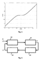
- the Figures 6 and 7 respectively illustrate the trend as a function of time t of the raw pressure signals P R 700 and filtered P 701 and the shape of the derivative of these same signals dP R / dt 800 and dP / dt 801.
- An accurate determination of the start of the combustion is therefore possible on the basis of the filtered pressure signal as generated by the method according to the invention.
- the apparent energy release dQ / dt is determined according to the relation: dQ dt ⁇
- t 1 ⁇ - 1 ⁇ V t ⁇ dP dt ⁇
- the date t0 combustion start is for example given by the formula: t ⁇ 0 such as d Q d t ⁇
- the noise emission power of the engine is determined directly from the derivative of the filtered pressure signal dP / dt.
- the setpoint vector y r comprises, for example, a set value of the power of the motor and a set value of the sound transmission power. Setpoints are preferably average values established for a thermodynamic cycle or established over several cycles.
- the servocontrol vector x comprises, for example, the instantaneous value of the filtered pressure p by the filtering device according to the invention as well as the derivative dP / dt of this pressure value, data from which a real value of the power of the motor and a real value of the sound emission power can be determined for comparison with the corresponding values of the target vector. On the basis of this comparison, the control module 600 then determines the command to be generated for the engine.
Landscapes
- Engineering & Computer Science (AREA)
- Chemical & Material Sciences (AREA)
- Combustion & Propulsion (AREA)
- Physics & Mathematics (AREA)
- General Physics & Mathematics (AREA)
- Mechanical Engineering (AREA)
- General Engineering & Computer Science (AREA)
- Combined Controls Of Internal Combustion Engines (AREA)
- Measuring Fluid Pressure (AREA)
Claims (9)
- Steuervorrichtung eines Verbrennungsmotors (601), die Mittel (600) zum Erzeugen eines Steuersignals des Verbrennungsmotors (601), einen Sensor (602) zur Lieferung eines Druckmessersignals einer Verbrennungskammer des Verbrennungsmotors (601) und eine Filtervorrichtung (603) aufweist, die es erlaubt, ein gefiltertes Drucksignal zu erzeugen, wobei die Filtervorrichtung (603) ausgehend von elektronischen analogen Bauteilen hergestellt ist und eine Konfiguration in geschlossener Schleife mit einem direkten Teil (201, 202, 203, 204) und einem Rücklaufteil (205) aufweist, wobei der Rücklaufteil ein Rückkopplungsmodul (205) des gefilterten Drucksignals (P) aufweist, und wobei der direkte Teil der Schleife Folgendes aufweist:- ein erstes Subtrahiermodul (201), das geeignet ist, den Unterschied zwischen dem Druckmesssignal (Pr) und dem Ausgang des Rückkopplungsmoduls (205) zu erzeugen,- ein nicht lineares statisches Modul (202) am Ausgang des Subtrahiermoduls, das geeignet ist, die Schwingungen mit geringen Amplituden zu dämpfen, die in dem Unterschiedsignal am Ausgang des Rückkopplungsmoduls enthalten sind,- ein Integriermodul (204), das geeignet ist, das gefilterte Drucksignal (P) durch Integration ausgehend von dem Ausgang des nicht linearen Moduls zu erzeugen,wobei die Steuervorrichtung dadurch gekennzeichnet ist, dass sie Folgendes aufweist:- ein zweites Subtrahiermodul (206), das geeignet ist, den Unterschied zwischen dem Druckmesssignal (Pr) und dem gefilterten Drucksignal (P) zu erzeugen,- ein Tiefpassfiltermodul (207) am Ausgang des zweiten Subtrahiermoduls,- ein Addiermodul (208), das geeignet ist, ein korrigiertes gefiltertes Drucksignal (Pout) in der Form der Summe aus dem gefilterten Drucksignal (P) und dem Ausgang des Tiefpassfiltermoduls (207) zu erzeugen.
- Vorrichtung nach Anspruch 1, dadurch gekennzeichnet, dass das erste Subtrahiermodul (201), das nicht lineare Modul (202) und das Integriermodul (204) in dem direkten Teil der Filterschleife in Serie geschaltet sind.
- Vorrichtung nach einem der vorhergehenden Ansprüche, dadurch gekennzeichnet, dass das Signal am Eingang des Integriermoduls (204) bis auf eine multiplizierende Verstärkung das Signal ist, das der zeitlichen Drift des gefilterten Drucksignals (P) entspricht.
- Vorrichtung nach einem der vorhergehenden Ansprüche, dadurch gekennzeichnet, dass sie wenigstens ein Multiplikationsmodul (203) aufweist, das es erlaubt, die Verstärkung einzustellen, die an das gefilterte Drucksignal vor der Rückkopplung angewandt wird.
- Vorrichtung nach einem der vorhergehenden Ansprüche, dadurch gekennzeichnet, dass die von dem nicht linearen Modul ausgeführte Funktion eine Funktion des einfachen oder harten Schwellenwertbildens ist.
- Vorrichtung nach einem der vorhergehenden Ansprüche, dadurch gekennzeichnet, dass das nicht lineare Modul (202) ausgehend von wenigstens einem Widerstand und wenigstens zwei Dioden, die auf den Kopf gestellt und parallel angeschlossen sind, hergestellt ist.
- Vorrichtung nach einem der vorhergehenden Ansprüche, dadurch gekennzeichnet, dass das erste Subtrahiermodul (201) oder das zweite Subtrahiermodul (206) oder das Addiermodul (208) ausgehend von einem operativen Verstärker und wenigstens einem Widerstand hergestellt ist.
- Vorrichtung nach einem der vorhergehenden Ansprüche, dadurch gekennzeichnet, dass das Integriermodul (204) ausgehend von wenigstens einem Widerstand und einer Kapazität hergestellt ist.
- Vorrichtung nach einem der vorhergehenden Ansprüche, dadurch gekennzeichnet, dass das Tiefpassfiltermodul (207) ausgehend von wenigstens einem Widerstand und einer Kapazität hergestellt ist.
Applications Claiming Priority (2)
| Application Number | Priority Date | Filing Date | Title |
|---|---|---|---|
| FR0412252A FR2878030B1 (fr) | 2004-11-18 | 2004-11-18 | Dispositif de filtrage d'un signal de mesure de pression |
| PCT/FR2005/050965 WO2006054029A1 (fr) | 2004-11-18 | 2005-11-18 | Dispositif de commande d'un moteur a combustion interne |
Publications (2)
| Publication Number | Publication Date |
|---|---|
| EP1815223A1 EP1815223A1 (de) | 2007-08-08 |
| EP1815223B1 true EP1815223B1 (de) | 2013-04-10 |
Family
ID=34950787
Family Applications (1)
| Application Number | Title | Priority Date | Filing Date |
|---|---|---|---|
| EP05819400.2A Expired - Lifetime EP1815223B1 (de) | 2004-11-18 | 2005-11-18 | Vorrichtung zur steuerung eines verbrennungsmotors |
Country Status (6)
| Country | Link |
|---|---|
| US (1) | US7974768B2 (de) |
| EP (1) | EP1815223B1 (de) |
| JP (1) | JP4832446B2 (de) |
| KR (1) | KR101217916B1 (de) |
| FR (1) | FR2878030B1 (de) |
| WO (1) | WO2006054029A1 (de) |
Families Citing this family (10)
| Publication number | Priority date | Publication date | Assignee | Title |
|---|---|---|---|---|
| FR2911911B1 (fr) * | 2007-01-26 | 2015-03-27 | Renault Sas | Procede de traitement d'un signal de pression et dispositif correspondant. |
| FR2922261A1 (fr) * | 2007-10-11 | 2009-04-17 | Renault Sas | Systeme et procede de compensation de la derive d'un signal issu d'un capteur de pression cylindre |
| FR2927420B1 (fr) * | 2008-02-13 | 2010-02-26 | Continental Automotive France | Dispositif de mesure de pression et procede correspondant |
| FR2938645B1 (fr) * | 2008-11-19 | 2012-03-02 | Continental Automotive France | Procede de correction de la derive du signal d'un capteur de pression |
| FR2964738B1 (fr) * | 2010-09-10 | 2013-06-21 | Yzatec | Procede et circuit de traitement d'un signal delivre par un capteur piezoelectrique et dispositif de mesure de pression pour machine a piston(s) |
| WO2013191267A1 (ja) * | 2012-06-21 | 2013-12-27 | 日立オートモティブシステムズ株式会社 | 内燃機関の制御装置 |
| FR3011581B1 (fr) * | 2013-10-08 | 2018-08-24 | Continental Automotive France | Procede de compensation d'un signal d'un dispositif de mesure de pression au sein d'un moteur a combustion interne |
| US10082436B2 (en) * | 2013-11-14 | 2018-09-25 | Inficon Gmbh | Method for processing a measurement signal from a pressure measurement cell, and a measurement cell arrangement |
| DE102018101773B4 (de) * | 2018-01-26 | 2019-11-14 | Dr. Ing. H.C. F. Porsche Aktiengesellschaft | Verfahren und Vorrichtung zur Wassereinspritzung |
| CN110542254B (zh) * | 2019-08-30 | 2020-09-01 | 珠海格力电器股份有限公司 | 冷水机组、其进出水压调节方法及空调系统 |
Family Cites Families (12)
| Publication number | Priority date | Publication date | Assignee | Title |
|---|---|---|---|---|
| US2931901A (en) * | 1954-12-01 | 1960-04-05 | Honeywell Regulator Co | Nonlinear control apparatus |
| US3654563A (en) * | 1965-10-15 | 1972-04-04 | Gen Electric | Active filter circuit having nonlinear properties |
| NL7509592A (nl) * | 1974-10-12 | 1976-04-14 | Hartmann & Braun Ag | Schakeling voor het onderdrukken van stoorsig- nalen bij meetsignalen. |
| US3977239A (en) * | 1976-01-02 | 1976-08-31 | Rca Corporation | Engine diagnosis from frequency components in exhaust |
| DE2712303C3 (de) * | 1977-03-21 | 1982-09-16 | Siemens AG, 1000 Berlin und 8000 München | Schaltungsanordnung zur Unterdrückung des Störanteils in verrauschten Meßsignalen |
| SU792554A1 (ru) * | 1978-12-25 | 1980-12-30 | Сибирский металлургический институт им. Серго Орджоникидзе | Сглаживающее устройство |
| US6598468B2 (en) * | 2001-07-11 | 2003-07-29 | Cummins Inc. | Apparatus and methods for determining start of combustion for an internal combustion engine |
| KR100552210B1 (ko) * | 2004-06-28 | 2006-02-13 | 현대자동차주식회사 | 엔진 설계시 최소 오일 레벨 설정을 위한 시험용 엔진의공기혼입율 측정장치 및 측정방법 |
| SE0402813L (sv) * | 2004-11-17 | 2005-10-04 | Softube Ab | Ett system och en metod för simulering av akustisk rundgång |
| JP4271652B2 (ja) * | 2004-12-27 | 2009-06-03 | 本田技研工業株式会社 | 筒内圧検出装置 |
| US7246005B2 (en) * | 2005-06-07 | 2007-07-17 | Arvin Technologies, Inc. | Method and apparatus for controlling a component by feed-forward closed-loop controller state modification |
| US7444234B2 (en) * | 2007-01-31 | 2008-10-28 | Gm Global Technology Operations, Inc. | Method and apparatus for monitoring an intake air filter |
-
2004
- 2004-11-18 FR FR0412252A patent/FR2878030B1/fr not_active Expired - Fee Related
-
2005
- 2005-11-18 US US11/719,559 patent/US7974768B2/en not_active Expired - Fee Related
- 2005-11-18 EP EP05819400.2A patent/EP1815223B1/de not_active Expired - Lifetime
- 2005-11-18 KR KR1020077012827A patent/KR101217916B1/ko not_active Expired - Fee Related
- 2005-11-18 WO PCT/FR2005/050965 patent/WO2006054029A1/fr not_active Ceased
- 2005-11-18 JP JP2007542064A patent/JP4832446B2/ja not_active Expired - Fee Related
Also Published As
| Publication number | Publication date |
|---|---|
| FR2878030A1 (fr) | 2006-05-19 |
| WO2006054029A1 (fr) | 2006-05-26 |
| KR101217916B1 (ko) | 2013-01-02 |
| FR2878030B1 (fr) | 2007-04-27 |
| US7974768B2 (en) | 2011-07-05 |
| US20090153337A1 (en) | 2009-06-18 |
| KR20070068477A (ko) | 2007-06-29 |
| JP4832446B2 (ja) | 2011-12-07 |
| EP1815223A1 (de) | 2007-08-08 |
| JP2008520893A (ja) | 2008-06-19 |
Similar Documents
| Publication | Publication Date | Title |
|---|---|---|
| EP1815223B1 (de) | Vorrichtung zur steuerung eines verbrennungsmotors | |
| EP2436003A1 (de) | Verfahren und einrichtung zur schmalband-rauschunterdrückung in einem fahrzeug-innenraum | |
| WO2010057571A1 (fr) | Procede de correction de la derive du signal d'un capteur de pression | |
| WO2007101946A1 (fr) | Methode d'estimation en temps reel de parametres de combustion moteur a partir de signaux vibratoires | |
| FR2677096A1 (fr) | Dispositif d'attenuation des vibrations periodiques d'une structure mecanique. | |
| FR2524554A1 (fr) | Appareil de reglage du fonctionnement d'un moteur a combustion interne | |
| FR2842904A1 (fr) | Procede permettant de determiner un flux massique d'air | |
| FR3011581A1 (fr) | Procede de compensation d'un signal d'un dispositif de mesure de pression au sein d'un moteur a combustion interne | |
| FR3040220A1 (fr) | Systeme de regulation d'un parametre regule | |
| EP0534813B1 (de) | Verfahren zur Korrektur von Steuerparametern einer Brennkraftmaschine und Vorrichtung zur Durchführung des Verfahrens | |
| FR2467396A1 (fr) | Detecteur de cliquetis pour un moteur a combustion interne | |
| EP2898306B1 (de) | Signalverarbeitungsverfahren für ein druckmessungseinrichtung in eine verbrennungsmaschine | |
| WO2008046560A1 (fr) | Dispositif de détermination d'une erreur induite par un filtre passe-haut et méthode de correction d'erreur associée | |
| FR2872282A1 (fr) | Procede de traitement d'un signal de pression | |
| EP0655554A1 (de) | Verfahren zur Korrektur von Drehmomentstössen einer inneren Brennkraftmaschine | |
| FR2969279A1 (fr) | Capteur comprenant un detecteur piezoelectrique a compensation de defauts de masse | |
| FR3017946A1 (fr) | Procede de determination d'un debit traversant une vanne | |
| WO2020182808A1 (fr) | Correction de la mesure de pression d'un capteur de pression de cylindre | |
| FR2922261A1 (fr) | Systeme et procede de compensation de la derive d'un signal issu d'un capteur de pression cylindre | |
| FR2885749A1 (fr) | Dispositif de traitement de signal, en particulier pour un signal de position d'une pedale d'accelerateur de vehicule | |
| EP0618355A1 (de) | Verfahren und Einrichtung zur Steuerung des Betriebs einer Brennkraftmaschine eines Kraftfahrzeuges | |
| EP1907679A2 (de) | Vorrichtung und verfahren zum verarbeiten eines signals zur druckmessung einer verbrennungskammer eines internen verbrennungsmotors | |
| EP1888901B1 (de) | Verfahren zur rauschunterdrückung in einem einspritzdieselmotor | |
| EP4544164A1 (de) | Verfahren zur einstellung einer positionsservosteuerung eines aktuators, wie etwa eines kraftfahrzeugaktuators | |
| FR3141520A1 (fr) | Dispositif de détermination de la position et/ou de la vitesse d’une partie mobile d’une machine électrique et procédé associé |
Legal Events
| Date | Code | Title | Description |
|---|---|---|---|
| PUAI | Public reference made under article 153(3) epc to a published international application that has entered the european phase |
Free format text: ORIGINAL CODE: 0009012 |
|
| 17P | Request for examination filed |
Effective date: 20070618 |
|
| AK | Designated contracting states |
Kind code of ref document: A1 Designated state(s): AT BE BG CH CY CZ DE DK EE ES FI FR GB GR HU IE IS IT LI LT LU LV MC NL PL PT RO SE SI SK TR |
|
| RIN1 | Information on inventor provided before grant (corrected) |
Inventor name: MARTINEZ, DIDIER Inventor name: CORDESSES, LIONEL |
|
| DAX | Request for extension of the european patent (deleted) | ||
| 17Q | First examination report despatched |
Effective date: 20081218 |
|
| REG | Reference to a national code |
Ref country code: DE Ref legal event code: R079 Ref document number: 602005039072 Country of ref document: DE Free format text: PREVIOUS MAIN CLASS: G01L0023080000 Ipc: G01M0015080000 |
|
| RIC1 | Information provided on ipc code assigned before grant |
Ipc: G01M 15/08 20060101AFI20120828BHEP Ipc: F02D 35/02 20060101ALI20120828BHEP Ipc: G01L 23/08 20060101ALI20120828BHEP |
|
| GRAP | Despatch of communication of intention to grant a patent |
Free format text: ORIGINAL CODE: EPIDOSNIGR1 |
|
| GRAS | Grant fee paid |
Free format text: ORIGINAL CODE: EPIDOSNIGR3 |
|
| GRAA | (expected) grant |
Free format text: ORIGINAL CODE: 0009210 |
|
| AK | Designated contracting states |
Kind code of ref document: B1 Designated state(s): AT BE BG CH CY CZ DE DK EE ES FI FR GB GR HU IE IS IT LI LT LU LV MC NL PL PT RO SE SI SK TR |
|
| REG | Reference to a national code |
Ref country code: GB Ref legal event code: FG4D Free format text: NOT ENGLISH |
|
| REG | Reference to a national code |
Ref country code: CH Ref legal event code: EP Ref country code: AT Ref legal event code: REF Ref document number: 606253 Country of ref document: AT Kind code of ref document: T Effective date: 20130415 |
|
| REG | Reference to a national code |
Ref country code: IE Ref legal event code: FG4D Free format text: LANGUAGE OF EP DOCUMENT: FRENCH |
|
| REG | Reference to a national code |
Ref country code: DE Ref legal event code: R096 Ref document number: 602005039072 Country of ref document: DE Effective date: 20130606 |
|
| PG25 | Lapsed in a contracting state [announced via postgrant information from national office to epo] |
Ref country code: SI Free format text: LAPSE BECAUSE OF FAILURE TO SUBMIT A TRANSLATION OF THE DESCRIPTION OR TO PAY THE FEE WITHIN THE PRESCRIBED TIME-LIMIT Effective date: 20130410 |
|
| REG | Reference to a national code |
Ref country code: AT Ref legal event code: MK05 Ref document number: 606253 Country of ref document: AT Kind code of ref document: T Effective date: 20130410 |
|
| REG | Reference to a national code |
Ref country code: NL Ref legal event code: VDEP Effective date: 20130410 Ref country code: LT Ref legal event code: MG4D |
|
| PG25 | Lapsed in a contracting state [announced via postgrant information from national office to epo] |
Ref country code: IS Free format text: LAPSE BECAUSE OF FAILURE TO SUBMIT A TRANSLATION OF THE DESCRIPTION OR TO PAY THE FEE WITHIN THE PRESCRIBED TIME-LIMIT Effective date: 20130810 Ref country code: FI Free format text: LAPSE BECAUSE OF FAILURE TO SUBMIT A TRANSLATION OF THE DESCRIPTION OR TO PAY THE FEE WITHIN THE PRESCRIBED TIME-LIMIT Effective date: 20130410 Ref country code: ES Free format text: LAPSE BECAUSE OF FAILURE TO SUBMIT A TRANSLATION OF THE DESCRIPTION OR TO PAY THE FEE WITHIN THE PRESCRIBED TIME-LIMIT Effective date: 20130721 Ref country code: GR Free format text: LAPSE BECAUSE OF FAILURE TO SUBMIT A TRANSLATION OF THE DESCRIPTION OR TO PAY THE FEE WITHIN THE PRESCRIBED TIME-LIMIT Effective date: 20130711 Ref country code: NL Free format text: LAPSE BECAUSE OF FAILURE TO SUBMIT A TRANSLATION OF THE DESCRIPTION OR TO PAY THE FEE WITHIN THE PRESCRIBED TIME-LIMIT Effective date: 20130410 Ref country code: LT Free format text: LAPSE BECAUSE OF FAILURE TO SUBMIT A TRANSLATION OF THE DESCRIPTION OR TO PAY THE FEE WITHIN THE PRESCRIBED TIME-LIMIT Effective date: 20130410 Ref country code: SE Free format text: LAPSE BECAUSE OF FAILURE TO SUBMIT A TRANSLATION OF THE DESCRIPTION OR TO PAY THE FEE WITHIN THE PRESCRIBED TIME-LIMIT Effective date: 20130410 Ref country code: AT Free format text: LAPSE BECAUSE OF FAILURE TO SUBMIT A TRANSLATION OF THE DESCRIPTION OR TO PAY THE FEE WITHIN THE PRESCRIBED TIME-LIMIT Effective date: 20130410 Ref country code: PT Free format text: LAPSE BECAUSE OF FAILURE TO SUBMIT A TRANSLATION OF THE DESCRIPTION OR TO PAY THE FEE WITHIN THE PRESCRIBED TIME-LIMIT Effective date: 20130812 |
|
| PG25 | Lapsed in a contracting state [announced via postgrant information from national office to epo] |
Ref country code: CY Free format text: LAPSE BECAUSE OF FAILURE TO SUBMIT A TRANSLATION OF THE DESCRIPTION OR TO PAY THE FEE WITHIN THE PRESCRIBED TIME-LIMIT Effective date: 20130410 Ref country code: BG Free format text: LAPSE BECAUSE OF FAILURE TO SUBMIT A TRANSLATION OF THE DESCRIPTION OR TO PAY THE FEE WITHIN THE PRESCRIBED TIME-LIMIT Effective date: 20130710 Ref country code: LV Free format text: LAPSE BECAUSE OF FAILURE TO SUBMIT A TRANSLATION OF THE DESCRIPTION OR TO PAY THE FEE WITHIN THE PRESCRIBED TIME-LIMIT Effective date: 20130410 Ref country code: PL Free format text: LAPSE BECAUSE OF FAILURE TO SUBMIT A TRANSLATION OF THE DESCRIPTION OR TO PAY THE FEE WITHIN THE PRESCRIBED TIME-LIMIT Effective date: 20130410 |
|
| PG25 | Lapsed in a contracting state [announced via postgrant information from national office to epo] |
Ref country code: CZ Free format text: LAPSE BECAUSE OF FAILURE TO SUBMIT A TRANSLATION OF THE DESCRIPTION OR TO PAY THE FEE WITHIN THE PRESCRIBED TIME-LIMIT Effective date: 20130410 Ref country code: SK Free format text: LAPSE BECAUSE OF FAILURE TO SUBMIT A TRANSLATION OF THE DESCRIPTION OR TO PAY THE FEE WITHIN THE PRESCRIBED TIME-LIMIT Effective date: 20130410 Ref country code: EE Free format text: LAPSE BECAUSE OF FAILURE TO SUBMIT A TRANSLATION OF THE DESCRIPTION OR TO PAY THE FEE WITHIN THE PRESCRIBED TIME-LIMIT Effective date: 20130410 Ref country code: DK Free format text: LAPSE BECAUSE OF FAILURE TO SUBMIT A TRANSLATION OF THE DESCRIPTION OR TO PAY THE FEE WITHIN THE PRESCRIBED TIME-LIMIT Effective date: 20130410 |
|
| PLBE | No opposition filed within time limit |
Free format text: ORIGINAL CODE: 0009261 |
|
| STAA | Information on the status of an ep patent application or granted ep patent |
Free format text: STATUS: NO OPPOSITION FILED WITHIN TIME LIMIT |
|
| PG25 | Lapsed in a contracting state [announced via postgrant information from national office to epo] |
Ref country code: RO Free format text: LAPSE BECAUSE OF FAILURE TO SUBMIT A TRANSLATION OF THE DESCRIPTION OR TO PAY THE FEE WITHIN THE PRESCRIBED TIME-LIMIT Effective date: 20130410 Ref country code: IT Free format text: LAPSE BECAUSE OF FAILURE TO SUBMIT A TRANSLATION OF THE DESCRIPTION OR TO PAY THE FEE WITHIN THE PRESCRIBED TIME-LIMIT Effective date: 20130410 |
|
| 26N | No opposition filed |
Effective date: 20140113 |
|
| REG | Reference to a national code |
Ref country code: DE Ref legal event code: R097 Ref document number: 602005039072 Country of ref document: DE Effective date: 20140113 |
|
| BERE | Be: lapsed |
Owner name: RENAULT S.A.S. Effective date: 20131130 |
|
| REG | Reference to a national code |
Ref country code: CH Ref legal event code: PL |
|
| GBPC | Gb: european patent ceased through non-payment of renewal fee |
Effective date: 20131118 |
|
| PG25 | Lapsed in a contracting state [announced via postgrant information from national office to epo] |
Ref country code: CH Free format text: LAPSE BECAUSE OF NON-PAYMENT OF DUE FEES Effective date: 20131130 Ref country code: LI Free format text: LAPSE BECAUSE OF NON-PAYMENT OF DUE FEES Effective date: 20131130 Ref country code: MC Free format text: LAPSE BECAUSE OF FAILURE TO SUBMIT A TRANSLATION OF THE DESCRIPTION OR TO PAY THE FEE WITHIN THE PRESCRIBED TIME-LIMIT Effective date: 20130410 |
|
| REG | Reference to a national code |
Ref country code: IE Ref legal event code: MM4A |
|
| PG25 | Lapsed in a contracting state [announced via postgrant information from national office to epo] |
Ref country code: BE Free format text: LAPSE BECAUSE OF NON-PAYMENT OF DUE FEES Effective date: 20131130 |
|
| PG25 | Lapsed in a contracting state [announced via postgrant information from national office to epo] |
Ref country code: IE Free format text: LAPSE BECAUSE OF NON-PAYMENT OF DUE FEES Effective date: 20131118 |
|
| PG25 | Lapsed in a contracting state [announced via postgrant information from national office to epo] |
Ref country code: GB Free format text: LAPSE BECAUSE OF NON-PAYMENT OF DUE FEES Effective date: 20131118 |
|
| PG25 | Lapsed in a contracting state [announced via postgrant information from national office to epo] |
Ref country code: TR Free format text: LAPSE BECAUSE OF FAILURE TO SUBMIT A TRANSLATION OF THE DESCRIPTION OR TO PAY THE FEE WITHIN THE PRESCRIBED TIME-LIMIT Effective date: 20130410 |
|
| PG25 | Lapsed in a contracting state [announced via postgrant information from national office to epo] |
Ref country code: HU Free format text: LAPSE BECAUSE OF FAILURE TO SUBMIT A TRANSLATION OF THE DESCRIPTION OR TO PAY THE FEE WITHIN THE PRESCRIBED TIME-LIMIT; INVALID AB INITIO Effective date: 20051118 Ref country code: LU Free format text: LAPSE BECAUSE OF NON-PAYMENT OF DUE FEES Effective date: 20131118 |
|
| REG | Reference to a national code |
Ref country code: FR Ref legal event code: PLFP Year of fee payment: 11 |
|
| REG | Reference to a national code |
Ref country code: FR Ref legal event code: PLFP Year of fee payment: 12 |
|
| REG | Reference to a national code |
Ref country code: FR Ref legal event code: PLFP Year of fee payment: 13 |
|
| PGFP | Annual fee paid to national office [announced via postgrant information from national office to epo] |
Ref country code: DE Payment date: 20211118 Year of fee payment: 17 |
|
| REG | Reference to a national code |
Ref country code: DE Ref legal event code: R119 Ref document number: 602005039072 Country of ref document: DE |
|
| P01 | Opt-out of the competence of the unified patent court (upc) registered |
Effective date: 20230608 |
|
| PG25 | Lapsed in a contracting state [announced via postgrant information from national office to epo] |
Ref country code: DE Free format text: LAPSE BECAUSE OF NON-PAYMENT OF DUE FEES Effective date: 20230601 |
|
| PGFP | Annual fee paid to national office [announced via postgrant information from national office to epo] |
Ref country code: FR Payment date: 20241128 Year of fee payment: 20 |