EP1815251B1 - Massgeschneiderte magnetische partikel und verfahren zur herstellung davon - Google Patents
Massgeschneiderte magnetische partikel und verfahren zur herstellung davon Download PDFInfo
- Publication number
- EP1815251B1 EP1815251B1 EP05804627A EP05804627A EP1815251B1 EP 1815251 B1 EP1815251 B1 EP 1815251B1 EP 05804627 A EP05804627 A EP 05804627A EP 05804627 A EP05804627 A EP 05804627A EP 1815251 B1 EP1815251 B1 EP 1815251B1
- Authority
- EP
- European Patent Office
- Prior art keywords
- magnetic
- particles
- particle
- ferromagnetic
- field
- Prior art date
- Legal status (The legal status is an assumption and is not a legal conclusion. Google has not performed a legal analysis and makes no representation as to the accuracy of the status listed.)
- Expired - Lifetime
Links
Images


Classifications
-
- G—PHYSICS
- G01—MEASURING; TESTING
- G01N—INVESTIGATING OR ANALYSING MATERIALS BY DETERMINING THEIR CHEMICAL OR PHYSICAL PROPERTIES
- G01N33/00—Investigating or analysing materials by specific methods not covered by groups G01N1/00 - G01N31/00
- G01N33/48—Biological material, e.g. blood, urine; Haemocytometers
- G01N33/50—Chemical analysis of biological material, e.g. blood, urine; Testing involving biospecific ligand binding methods; Immunological testing
- G01N33/53—Immunoassay; Biospecific binding assay; Materials therefor
- G01N33/543—Immunoassay; Biospecific binding assay; Materials therefor with an insoluble carrier for immobilising immunochemicals
- G01N33/54313—Immunoassay; Biospecific binding assay; Materials therefor with an insoluble carrier for immobilising immunochemicals the carrier being characterised by its particulate form
- G01N33/54326—Magnetic particles
- G01N33/5434—Magnetic particles using magnetic particle immunoreagent carriers which constitute new materials per se
-
- Y—GENERAL TAGGING OF NEW TECHNOLOGICAL DEVELOPMENTS; GENERAL TAGGING OF CROSS-SECTIONAL TECHNOLOGIES SPANNING OVER SEVERAL SECTIONS OF THE IPC; TECHNICAL SUBJECTS COVERED BY FORMER USPC CROSS-REFERENCE ART COLLECTIONS [XRACs] AND DIGESTS
- Y10—TECHNICAL SUBJECTS COVERED BY FORMER USPC
- Y10T—TECHNICAL SUBJECTS COVERED BY FORMER US CLASSIFICATION
- Y10T428/00—Stock material or miscellaneous articles
- Y10T428/29—Coated or structually defined flake, particle, cell, strand, strand portion, rod, filament, macroscopic fiber or mass thereof
- Y10T428/2982—Particulate matter [e.g., sphere, flake, etc.]
- Y10T428/2991—Coated
Definitions
- the invention generally relates to magnetic particles for which magnetic properties are tailored to provide a specific response when a fluid suspension of the particles is subjected to an external magnetic field. More precisely, the invention concerns a method of preparing magnetic particles with specific magnetic properties and a method of manipulating them with a magnetic field. Further, the invention relates to the use of magnetic particles of the above kind for assaying, manipulation and purification of biomolecules and chemical substances.
- the particles are magnetic in the sense that they are capable of being magnetised in the presence of a magnetic field even though they are not themselves magnetic in the absence of a magnetic field.
- magnetic responsive particles are widely known and used as solid phase support for biological and chemical analysis.
- the magnetic particles surface can be activated to carry a probe that specifically interacts with complementary target molecules.
- the advantage of using magnetic particles is that they can be simply manipulated using a magnetic field to control the reaction on their surface and/or to separate the specific target molecule from the initial "contaminant" surrounding medium. Magnetic particle based procedures and systems are relatively rapid, easy and require simple equipment.
- Magnetic particles magnetic responsive particles
- residual magnetisation susceptibility factors
- Such consideration is important in order to minimize the agglomeration of magnetic particles during the manipulation process with a magnetic field. Indeed, the separation and manipulation of magnetic particles in liquid suspension necessitates the application of a "large" magnetic field and magnetic field gradient. In such conditions, monodispersed magnetic particles agglomerate under the influence of their mutual magnetic dipole interaction. Recovering a monodispersed magnetic particles suspension after magnetic field removal necessitates, therefore, a low residual dipolar magnetization of the particles.
- finer magnetic particles are used as primary magnetic material.
- the direction of the residual magnetization of the fine particles is so small that it can be reversed by the surrounding thermal energy fluctuations, leading to a vanishing average residual magnetisation.
- Supraparamagnetic particles are widely available on the market. They are known to be stable and highly monodispersed particles. However, one serious limitation associated with the above technologies is that magnetic particles present a low magnetic susceptibility due to the finer magnetic primary material. In this case, a high magnetic field is necessary to create a sufficient magnetic force to manipulate these particles. Moreover, magnetic particles (beads) of the above kind do not lend themselves to controlling and adapting their magnetic proprieties for specific applications, for instance obtaining different responses in correspondence with the applied magnetic field.
- the particles disclosed in US2004216810 are formed from a nano-size ferromagnetic core and an anti-ferromagnetic material shell.
- the shell material is associated with the ferromagnetic core to enhance the coercive field of the ferromagnetic core.
- Such particles are used for high density recording medium where high coercive field is required.
- the disclosure does not teach the adaptation and use of such core/shell for bio-magnetic separation.
- the use and benefit of magnetic particles with tailored magnetic response for bio-separation applications are proposed in US5932097 and more recently in US2002/0187504A1 .
- the first aspect of invention concerns magnetic responsive particles and a method for preparing them. These aims are attained with magnetic responsive particles and a method of preparing them according to independent claims 1 and 10 respectively.
- the second aspect of the invention is to provide a method of manipulating the said magnetic particles. This aim is attained with a method according to the independent claim 14.
- the third aspect of the invention discloses a method of using the magnetic particles prepared and manipulated following the previous aspects in live science and particularly for assaying, manipulation and purification of biomolecules and chemical substances. This aim is attained with independent claim 17.
- the first aspect of the invention provides a bio-chemically active magnetic particle for use in a magnetic particle fluid suspension for selectively binding with at least one target molecule, the particle comprising (a) a non-magnetic component; (b) a core/shell magnetic component; and (c) an external coating designed to allow an affinity recognition for selectively binding the particle with at least one target molecule.
- this first particle comprises a ferromagnetic core material and shell material;
- the shell materials can be chosen either among an antiferromagnetic material, a ferromagnetic material of a kind different from the core ferromagnetic material or transition metal material; the Néel temperature of the antiferromagnetic phase is above 300 K;
- the ferromagnetic core material comprises at least one fine ferromagnetic particle having zero coercive field or a given coercive field; and the fine ferromagnetic particle(s) is associated with the shell material to enhance the magnetic energy and to provide the particle with a coercive field much greater than that of the fine ferromagnetic particle(s).
- the coercive field of the particle according to the invention will generally be greater than 100 Oersted (Oe) at 300 K, usually above 200 (Oe) and preferably greater than 400 (Oe).
- the primary magnetic element in our invention is a "fine" ferromagnetic particle which has a zero coercive field or a given (usually low) coercive field and even behaves as a superparamagnetic at ordinary temperature.
- the idea is to put such ferromagnetic fine particle in association with a shell material, usually by direct contacting the two, to enhance the coercive field of the overall particle, due to the magnetic exchange coupling between the core and the shell.
- Nickel (Ni) magnetic particle of 10 nm diameter the coercive field of this particle is about 10 (Oe) at 300 K which is very low and the particle is substantially superparamagnetic at ordinary temperature.
- NiO Nickel oxide
- the coercive field increases to a value of about 250 (Oe).
- core/shell magnetic fine particles composed from a ferromagnetic core and magnetic metal shell such as Fe 2 O 3 /Co fine particles.
- the particle of the invention comprises at least one primary ferromagnetic fine particle that is associated with (in particular in contact with) a shell material to provide an enhanced coercive field.
- the above-mentioned primary responsive particles are ferromagnetic fine particles.
- the ferromagnetic material includes, but is not limited to, Cobalt (Co), Nickel (Ni), magnetite ( ⁇ -Fe 2 O 3 ) or any alloy thereof.
- Pt, FePt, PrCo 5 , Sm and CoPt are preferably used to provide a high coercive field.
- metals oxides and their alloys are preferred materials entering in the composition of the core/shell magnetic component.
- a magnetic a heat annealing step is preferred to adjust and increase the coercive field.
- the size of the fine ferromagnetic core which determines the magnetic response of the particles is preferably less than the critical size (i.e. the size above which the particle becomes a multi-domain particle) of a single magnetic domain.
- the size of the fine particles entering in the composition of the ferromagnetic core is in the nanometric size between 500 or 200 to 1nm and preferably between 50 or 25 to 5nm.
- ferromagnetic fine particles have acicular shape to increase the magnetic anisotropy and thus the coercive field.
- a method of preparing magnetic particles with a defined coercive field comprises the steps of:
- This method of the first aspect of the invention further comprises a step of adding a shell material in coexistence with the ferromagnetic phase material, i.e. advantageously the aforesaid fine ferromagnetic having zero coercive field or a given coercive field, in contact with the shell material.
- the shell materials can be chosen either among an antiferromagnetic material, a ferromagnetic magnetic of a kind different from the core ferromagnetic material or a metal material.
- the Néel temperature of the antiferromagnetic phase is not less than 300 K. Further, the ferromagnetic material phase and the antiferromagnetic phase are in a state to minimize the magnetic exchange bias coupling field (H e ) and to provide a specific coercive field (H c ). More specifically, it is preferable that the magnetic exchange bias coupling field is lower than the coercive field, (H e ⁇ H c ).
- antiferromagnetic phase materials can be used, such as, but not limited to, ferromagnetic oxide like NiO and several alloys like NiMn and FeMn.
- the particles prepared according to the method of the invention are substantially unmagnetized and preferably completely unmagnetized. Indeed, even composed from “permanently" magnetized primary fine particles the prepared secondary particle is substantially unmagnetized due to the random distribution of the magnetization of the fine primary particles within the non-magnetic matrix. However, the application of an external magnetic will align the magnetization of the primary fine particles along the applied field, leading therefore to the magnetization of the composed secondary particle.
- the secondary particle will acquire a permanent magnetic moment with a predefined coercive field that is controlled by adjusting the coercive field, the amount and the concentration of the primary fine particles within the non-magnetic matrix.
- the non-magnetic material forming notably the core of the secondary magnetic particles is preferably a polymeric material, silica or glass.
- the steps of preparing magnetic particles according to the first aspect of the invention preferably further comprise a heat annealing step to adjust and enhance the coercive field the secondary particles.
- the resulting magnetic particles present the advantage of have a rapid magnetic response even at low applied magnetic field. Moreover, contrary to the particles described in the prior art, the particles of the present invention take benefit from the "residual" magnetisation through the control of the magnetic hysteresis loss of the particle when the particles are manipulated with an alternating magnetic field.
- a method of manipulating magnetic particles according to the second aspect of the invention comprises the following steps:
- the method preferably further comprises a step of adding to the alternating/oscillating magnetic field a direct "positive" magnetic field component whose amplitude is equal to the magnetic exchange bias field.
- the particles preferably have a coercive field greater than or close to the amplitude of the applied alternating magnetic field.
- a method of using the magnetic particles according to the third aspect of the invention comprises contacting the magnetic particles obtained following the first aspect of the invention with a carrier fluid (usually containing samples to be processed for life science and chemical assays) and then manipulating the particles following the second aspect of the invention.
- a carrier fluid usually containing samples to be processed for life science and chemical assays
- the third aspect of the invention disclose a suspension that contains magnetic particles designed to respond with a defined magnetic coercive field to an external magnetic field.
- the surfaces of the said magnetic particles are specifically functionalized with affinity recognition group for selectively binding with target molecules.
- the said suspension is a part of a kit that includes other reagents required for assaying, manipulation and purification of biomolecules and chemical substances.
- the third aspect of the invention disclose a suspension that contains bio-functionalized magnetic particles designed to respond with a defined magnetic coercive field to the application of an external magnetic field.
- the surfaces of the said magnetic particles are specifically functionalized with affinity recognition group for selectively binding with target molecules.
- the magnetic particles are prepared to be unmagnetized before their use or manipulation using an external magnetic field. Instead, the particles will develop a controlled hysteretic response characterized by a specific coercive field when subjected to an external magnetic field. Contrary to the particles available on the market, which are designed to exhibit superparamagnetic behavior, the particles according the invention have a "large coercive field".
- the required coercive field is between 100 to 20'000 Oe and preferably between 200 to 1000 Oe.
- the said suspension is prepared following the first aspect of the invention.
- the said suspension is a part of a kit that includes other reagents required for assaying, manipulation and purification of biomolecules and chemical substances.
- the magnetic particles are manipulated following the second aspect of the invention.
- Figures 1 (a) (b) and (c) are cross sectional views of three magnetically responsive particles according to the first embodiment realising the first aspect of the invention.
- Figure 2 is a cross sectional view of a magnetically responsive particle according to a second embodiment realising the first aspect of the invention.
- Figure 3 is a cross sectional view of a magnetically responsive particle according to a third embodiment realising the first aspect of the invention, with a detail shown in enlargement.
- Figure 4 is a cross sectional view of a magnetically responsive particle according to a fourth embodiment realising the first aspect of the invention.
- Figure 5 is a cross sectional view of a magnetically responsive particle according to a fifth embodiment realising the first aspect of the invention.
- Figure 6 is a schematic view illustrating the behaviour of magnetic particle chains during their manipulation with an alternating magnetic field.
- Figures 7(a) and 7(b) graphically illustrate a step in the second aspect of the invention involving adding to an oscillating magnetic field a direct "positive" magnetic field component whose amplitude is equal to the magnetic exchange bias coupling field.
- Figure 7(c) is a schematic view illustrating the behaviour of magnetic particle chains during their manipulation with an alternating magnetic field combined with a lateral driving force.
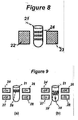
- Figure 8 is a schematic view illustrating the manipulation of magnetic particle chain aggregation structures using an alternating magnetic field in a test tube according to a sixth embodiment realising the second aspect of the invention.
- Figure 9 is a schematic view illustrating the manipulation of magnetic particles according to a seventh embodiment realising the second aspect of the invention, wherein magnetic chain aggregation structures are manipulated by an alternating magnetic field and transported along a test tube with a travelled magnetic field gradient.
- primary fine magnetic particles are composed from a ferromagnetic material particle core (1) coated with a fine shell material (2).
- the shell materials can be chosen either among antiferromagnetic material, a ferromagnetic magnetic of a kind different from the core ferromagnetic material or transition metal material.
- the Néel temperature of the antiferromagnetic phase is not less than 300 K.
- This primary fine particle is encapsulated in a non-magnetic material matrix (3).
- matrix material is a polymer, silica or glass.
- the surface (4) of the so-formed secondary magnetic responsive particle is bio-chemically functionalised by specific ligands for the probing and manipulating of biomolecules and chemical substances using well-known techniques.
- the magnetic particle surface comprises for example a functional group or a ligand that is capable of binding to a target molecule or to class of target molecules.
- Potential functional groups comprise but are not limited to carboxylic acids, hydroxamic acids, non-adhesive compounds, amines, isocyanates, and cyanides.
- Potential ligands comprise but are not limited to proteins, DNA, RNA, enzymes, hydrophobic materials, hydrophilic material, and antibodies.
- ligands suitable for use in the present invention include, but are not limited to, molecules and macromolecules such as proteins and fragments of proteins, peptides and polypeptides, antibodies, receptors, aptamers, enzymes, substrates, substrate analogs, ribozymes, structural proteins, nucleic acids such as DNA and RNA and DNA/RNA hybrids, saccharides, lipids, various hydrophobic or hydrophillic substances, lipophilic materials, chemoattractants, enzymes, hormones, fibronectin and the like.
- molecules and macromolecules may be naturally occurring or synthetic.
- the term ligand may also include larger entities such as cells, tissues, entire microorganisms, viruses, etc.
- the size of the fine ferromagnetic core (1) determines the magnetic response of the particles, and is preferably less than the size of a single magnetic domain. Particles with diameter larger than a magnetic domain contain a plurality of magnetic domains. In this case, larger energy in required to reverse the magnetisation of the particles which in turn appear in a lower coercive field. On the other hand, as the dimension of the particles becomes smaller, the particles' magnetisation becomes all the more susceptible to thermal fluctuation. To enhance the coercive field of the particles while maintaining their fine size, the ferromagnetic core (1) of the particle is coated with the thin specific material layer (2).
- the magnetic exchange in the interface between the ferromagnetic core (1) and thin layer (2) will considerably increase the anisotropy energy and therefore the coercive field.
- the thickness of the shell (2) one can consequently increase the coercive field.
- the ferromagnetic core is preferably acicular ( Figure 1(c) ) to increase the shape anisotropy compared with a spherical core ( Figure 1(a) ) or, to a lesser extent, with a generally oval or oblong one ( Figure 1(b) ).
- references 1, 5 and 6 indicate the ferromagnetic core which is preferably a single-domain core.
- the particle is a single-domain particle (fine particle).
- the mean diameter (or cross-dimension) of a single domain particle is generally less than 200 nm and preferably less than 25 nm.
- secondary magnetically responsive particles are obtained by encapsulating at least one of the primary fine magnetic particles (8) in particular of the kind described above in connection with Figure 1 in a non-magnetic material matrix (7).
- the amount, the size and the distribution within the matrix (7) of the primary fine particles (8) determine the entire magnetic proprieties of the final particle.
- the coercive field of the particle is set by adjusting first the coercive field of fine primary particles components and secondly by adjusting the size and the concentration of the fine particles (8) within the matrix (7).
- the surface (4) of the so-formed secondary magnetic responsive particle is bio-chemically functionalised, for example as described above.
- a third embodiment of the first aspect of the invention (shown in Figure 3 ), consists of secondary magnetically responsive particles obtained by the deposition of a layer (10) of primary fine magnetic particles (11) in particular of the kind described above in connection with Figure 1 on non-magnetic material bead (9).
- the thickness of the deposited layer (10), the concentration and the size of the primary fine particles (11) within the layer (10) determine the entire magnetic proprieties of the secondary particles.
- the coercive field of the secondary particle is set by adjusting first the coercive field of the deposited fine particles (11) and secondly by adjusting the size of the ferromagnetic core (1,5,6), the amount and concentration of the particles (11) within the layer (10) and the thickness of the layer (10).
- secondary magnetically responsive particles are obtained by the deposition on a non-magnetic bead (12), of a first layer composed of ferromagnetic fine particles (13) followed by a deposition of a second outer shell composed of specific material fine particles (14), also in particular the shell materials can be chosen either among antiferromagnetic material, a ferromagnetic material of a kind different from the core ferromagnetic material or a transition metal material.
- the Néel temperature of the antiferromagnetic fine particle phase is not less than 300 K.
- the thickness of the ferromagnetic layer and the specific material shell determines respectively the magnetic response and the coercive field of the secondary particles.
- the thickness of the antiferromagnetic shell (14) is controlled to minimize the magnetic bias field. For this, its thickness is lower than the limit above which magnetic exchange field coupling with the ferromagnetic layer becomes effective.
- Other factors that can contribute effectively to the magnetic properties of the secondary particle are the size, shape and the concentration of the primary ferromagnetic particles (13) forming the first ferromagnetic layer.
- secondary magnetically responsive particles are obtained by the deposition, on the surface of a non-magnetic bead (12), of a specific material fine particle layer (14') in which a quantity of primary fine ferromagnetic particles (13') are uniformly dispersed.
- the specific shell material can be chosen either among antiferromagnetic material, a ferromagnetic material of a kind different from the core ferromagnetic material or a transition metal material.
- the ferromagnetic particles (13') are in particular of the kind described above in connection with Figure 1 . In this case one can consider that the layer (14') forms a matrix in which the primary ferromagnetic fine particles (13') are dispersed.
- the thickness of the layer (14') and the concentration of the fine ferromagnetic particles (13') dispersed therein are controlled to provide a specific coercive field of the secondary particles.
- a heat annealing step is preferred to adjust and increase the coercive field the secondary particles.
- magnetic fine particles with large magnetic anisotropy such as FePt are required.
- the FePt fine particles are provided as a ferrofluid suspension with a disordered fcc FePt crystalline structure.
- Such structure has low anisotropy and hence needs to be thermally annealed in order to obtain the fct phase with high uniaxial magnetocrystalline anisotropy responsible for the high coercive field. Heating at 600° will lead to an increasing of the coercive field for larger values that can reach thousands of Oe.
- the fine particles are preferably dispersed in a non-magnetic matrix having large melting temperature such as glass.
- the thermal annealing step is particularly required when the particles according to the invention are synthesized starting from a ferrofluid suspension of supraparamagnetic nanoparticles.
- the ferrofluid is composed from nanoparticles with low crystalline magnetic anisotropy such as disordered or amorphous crystalline structures.
- a heating step is used to adjust the nanocrystals structure and provide the resulting secondary particles with larger magnetocrystalline anisotropy.
- a suspension of the magnetic particles synthesized in particular following the first aspect of the invention is introduced in a cell in which the particles will be manipulated using an external magnetic field.
- the particles will develop a magnetic moment in the direction of the applied field B (16). Due to their mutual magnetic dipole interaction, the individual particles align to form longer magnetic chain structures (15). Contrary to the case of supraparamagnetic material, even if the external magnetic field is removed or turned off, the magnetic chain structures (15) remain intact in the case where the particles used are those provided by the first aspect of the invention.
- a main feature of the second aspect of the invention consists in the manipulation of the magnetic aggregations by an alternating magnetic field to control the aggregation length.
- the "ideal extreme" state is reached when the smallest magnetic aggregation length is equal to the magnetic particle size, which obviously implies the application of a high frequency alternating magnetic field.
- the magnetic chain aggregations do not have enough time to follow the field alternations, which impose the use of magnetic particles with higher coercive field to reach lower aggregated particles state.
- the magnetic remanence and the coercive field Two physical characteristics of the magnetic particles are important in the manipulation of magnetic chain aggregations using an alternating magnetic field: the magnetic remanence and the coercive field. The higher these values, the higher the frequencies at which the magnetic chain aggregations can rotate. Moreover, to minimize the agglomeration of the magnetic particles under the application of an external alternating magnetic field, the coercive field of the particles is preferably greater or at least close to the amplitude of applied field. Increasing the hysteresis loss of the magnetic particles is, therefore, a main feature of manipulating magnetic particles using an alternating magnetic field.
- the magnetic particles are preferably realized following the first aspect of the invention. Moreover, the particles are preferably spherical and substantially monodispersed in size and magnetic proprieties. Instead, according to the second aspect of the invention the particles diameter is in the range of 10 nm to 100 ⁇ m, with dispersion that must be less than 30 % and more preferably less than 10%. Accordingly, the dispersion of the magnetic content of the particles (concentration of the fine particles within the matrix) is less than 30 % and more preferably less than 10 %.
- the magnetic particles are realized with a defined coercive field of the particles following the first aspect of the invention so that the smallest magnetic aggregation length is equal to the magnetic particle diameter.
- This fully disaggregated state is more preferably reached with particles that present a coercive field that is greater than or close to the amplitude of the applied alternating magnetic filed.
- this state is preferably reached for magnetic field amplitudes in the range of 0.01 Tesla to 1 Tesla and a field alternation frequency in the range of 0.1 Hz to 200 Hz.
- FIGS 7(a) and 7(b) graphically illustrate a step in the second aspect of the invention involving adding to an oscillating magnetic field a direct "positive" magnetic field component whose amplitude is equal to the magnetic exchange bias coupling field.
- a direct "positive" magnetic field component whose amplitude is equal to the magnetic exchange bias coupling field.
- the latter leads to a dissymmetry of the hysteresis loop which becomes non-centralized around zero.
- the invention aims to maximize the hysterisis loss when the particles are manipulated with an alternating magnetic field. To achieve this, the induced bias dissymmetry must be small compared to the coercive field. Moreover, even if a significant bias field is induced it is possible to compensate the induced dissymmetry by manipulating the particles with a "positively" shifted oscillating magnetic field as schematically shown in the right of Figure 7(b) . This can be done simply by adding a direct magnetic field component (B c ) having an amplitude equal to the magnetic bias coupling field.
- B c direct magnetic field component
- FIG. 7(c) Another main feature of the second aspect of the invention (as shown in Figure 7(c) ) consists in the manipulation of magnetic particle chain aggregations using an alternating magnetic field (17) while at the same time the magnetic particle chain aggregations are subjected to a transverse external force field F (20).
- the fields (17) and (20) are not uniform whereby the smaller magnetic chain aggregations (19) and (19') are not subjected to same forces leading, thus, to less aggregated magnetic chain structures.
- the external transverse force F is a magnetic gradient force and in another embodiment the external transverse force is a flow drag force.
- an amount of magnetic particles synthesized in particular following the first aspect of the invention is suspended in a test tube (21) between two magnetic poles (22,23).
- a static magnetic field is first applied covering the whole test tube volume to cause the formation of magnetic chain aggregation structures (24).
- the amount of the magnetic particles used is such that each particle chain aggregation (24) covers uniformly the test tube volume.
- An alternating magnetic field is then applied to cause a rotation of the magnetic chains in response to the field alternation. By adjusting the magnetic field amplitude and alternation frequency one can control the maximum magnetic chain length within the aggregations.
- the small magnetic chain rotation dynamics serves to mix the magnetic particles with the surrounding liquid medium.
- an amount of magnetic particles synthesized in particular following the first aspect of the invention is suspended in a test tube (21).
- the difference consists in the use of two couples of magnetic poles (24, 26) and (27, 28).
- the magnetic field generated from the first magnetic pole couple (24, 26) covers at least the upper half of the test tube volume while the second magnetic pole couple (24, 26) covers the remaining lower half of the test tube volume.
- a spatial overlap of the magnetic field generated by the two magnetic pole couples is a necessary condition in the functioning of the system.
- the magnetic pole couple (24,26) is actuated which results in the formation of magnetic chain aggregations (29).
- the amount of the magnetic particles used is such that the magnetic chain aggregations (29) form a dense structure substantially covering the test tube cross section.
- the aggregation length is controlled by adjusting the magnetic field amplitude and alternation frequency.
- the magnetic pole couple (24, 26) is turned off while the second magnetic pole couple (27,28) is actuated with an alternating magnetic field.
- the magnetic chain aggregation structure (29') will be attracted by the magnetic field gradient (30) generated by the pole couple (27, 28) and so transported along the test tube (21) from the upper volume space to the lower volume space. Since the magnetic field gradient force (30) generated by pole couple (27, 28) is not uniform, the small chain aggregations are not subjected to the same force, which leads to less-aggregated magnetic chain structures (29') during the transportation process.
- a method which consists in the use of a fluid suspension of the magnetic particles obtained following the first aspect of the invention and manipulated following the second and the third aspects of the invention in live science applications and particularly for assaying, manipulation and purification of biomolecules and chemical substances.
- the third aspect of the invention discloses a suspension that contains magnetic particles designed to respond with a defined magnetic coercive field to an external magnetic field.
- the surfaces of the said magnetic particles are specifically functionalized with affinity recognition group for selectively binding with target molecules.
- the said suspension is a part of a kit that includes other reagents required for assaying, manipulation and purification of biomolecules and chemical substances.
Landscapes
- Health & Medical Sciences (AREA)
- Immunology (AREA)
- Life Sciences & Earth Sciences (AREA)
- Engineering & Computer Science (AREA)
- Molecular Biology (AREA)
- Biomedical Technology (AREA)
- Chemical & Material Sciences (AREA)
- Hematology (AREA)
- Urology & Nephrology (AREA)
- Biotechnology (AREA)
- Biochemistry (AREA)
- Cell Biology (AREA)
- Food Science & Technology (AREA)
- Medicinal Chemistry (AREA)
- Physics & Mathematics (AREA)
- Analytical Chemistry (AREA)
- Microbiology (AREA)
- General Health & Medical Sciences (AREA)
- General Physics & Mathematics (AREA)
- Pathology (AREA)
- Soft Magnetic Materials (AREA)
- Immobilizing And Processing Of Enzymes And Microorganisms (AREA)
- Hard Magnetic Materials (AREA)
Claims (18)
- Biochemisch aktives Magnetpartikel zur Verwendung in einer Magnetpartikelfluidsuspension zur selektiven Bindung mit mindestens einem Zielmolekül, wobei das Partikel umfasst:a) eine nicht-magnetische Komponente;b) eine magnetische Kern/Hülle-Komponente, die ein ferromagnetisches Kernmaterial und ein Hüllmaterial umfasst, wobei das ferromagnetische Material mindestens ein ferromagnetisches Feinpartikel mit einem Null-Koerzitivfeld oder einem bestimmten Koerzitivfeld umfasst, wobei das oder die ferromagnetischen Feinpartikel mit der Hüllmaterialphase assoziiert sind, um ein Koerzitivfeld bereitzustellen, das viel größer als jenes des oder der ferromagnetischen Feinpartikel ist; undc) einen äußeren Überzug, der so gestaltet ist, dass eine Affinitätserkennung für eine selektive Bindung des Partikels mit mindestens einem Zielmolekül möglich ist.
- Partikel nach Anspruch 1, bestehend aus einem Kern aus dem ferromagnetischen Material, der mit einem Hüllmaterial überzogen ist, wobei beide Materialien die magnetische Komponente bilden, wobei die nicht-magnetische Komponente das magnetische Element einkapselt.
- Partikel nach Anspruch 1, umfassend mehrere der magnetischen Komponenten, von welchen jede aus einem Kern aus dem ferromagnetischen Material, der mit einem Hüllmaterial überzogen ist, besteht, wobei die magnetischen Komponenten in der nicht-magnetischen Komponente eingebettet sind.
- Partikel nach Anspruch 1, umfassend einen Kern, der aus der nicht-magnetischen Komponente besteht, die von einer Schicht überzogen ist, die mehrere der magnetischen Komponenten umfasst, wobei jede magnetische Komponente aus einem Kern aus dem ferromagnetischen Material, der mit Hüllmaterial überzogen ist, besteht.
- Partikel nach Anspruch 1, umfassend einen Kern, der aus der nicht-magnetischen Komponente besteht, die von einer ersten Schicht überzogen ist, die aus dem ferromagnetischen Material besteht, und einer zweiten feinen Schicht, die aus dem Hüllmaterial besteht.
- Partikel nach Anspruch 1, umfassend einen Kern, der aus der nicht-magnetischen Komponente besteht, die mit einer Schicht Hüllmaterial überzogen ist, in der mehrere ferromagnetische Elemente eingebettet sind.
- Partikel nach einem der Ansprüche 1 bis 6, wobei das ferromagnetische Kernmaterial ein Übergangsmetallmaterial ist.
- Partikel nach einem der Ansprüche 1 bis 7, wobei das Hüllmaterial ausgewählt sein kann aus einem anti-ferromagnetischen Material, einem ferromagnetischen Material einer Art, die sich von dem ferromagnetischen Material des Kerns unterscheidet, einem Übergangsmetall oder einem Metalloxidmaterial; wobei die Neel-Temperatur der anti-ferromagnetischen Phase über 300 K liegt.
- Partikel nach einem der Ansprüche 1 bis 8, wobei das Hüllmaterial eine Schicht bildet, deren Dicke ein spezifisches Koerzitivfeld liefert.
- Verfahren zur Herstellung von Magnetpartikeln mit einem bestimmten Koerzitivfeld, umfassend die folgenden Schritte:a) Bereitstellen primärer magnetisch reaktionsfähiger ferromagnetischer Feinpartikel mit einem Null-Koerzitivfeld oder einem definierten Koerzitivfeld über 300 K, wobei die Feinpartikel mit einer magnetischen Hüllmaterialphase assoziiert sind, um ein Koerzitivfeld bereitzustellen, das viel größer als jenes der ferromagnetischen Feinpartikel ist;b) Integrieren der primären Feinpartikel von Schritt a) in einen nicht-magnetischen Träger, um ein sekundäres Kernpartikel bereitzustellen;c) Einstellen des Koerzitivfeldes des sekundären Partikels durch Kontrolle des Ausmaßes und der Konzentration der primären Feinpartikel, die in Schritt a) bereitgestellt und im folgenden Schritt b) integriert wurden;d) Funktionalisieren der Oberfläche des erhaltenen Partikels nach den Schritten a) bis c) mit Affinitätserkennung für eine selektive Bindung mit einem Zielmolekül.
- Verfahren zur Herstellung von Magnetpartikeln nach Anspruch 10, das des Weiteren einen Wärmeglühschritt umfasst, um das Koerzitivfeld der sekundären Partikel einzustellen.
- Verfahren nach Anspruch 10, wobei das Koerzitivfeld der sekundären Partikel zwischen 100 und 20.000 Oe und vorzugsweise zwischen 200 und 1000 Oe liegt.
- Verfahren nach Anspruch 10, 11 oder 12, wobei die primären ferromagnetischen Feinpartikel eine Größe zwischen 1 und 500 nm und vorzugsweise zwischen 5 und 50 nm aufweisen.
- Verfahren zur Manipulation von Magnetpartikeln nach einem der Ansprüche 1 bis 9 oder hergestellt durch das Verfahren nach einem der Ansprüche 10 bis 13, in einer Magnetpartikelsuspension, wobei das Verfahren die folgenden Schritte umfasst:a) Bereitstellen einer Suspension von im Wesentlichen unmagnetisierten Magnetpartikeln und die eine Hysteresereaktion mit einem spezifischen Koerzitivfeld in Gegenwart eines externen Magnetfeldes zeigen;b) Einbringen einer Menge an Magnetpartikeln in Suspension in einer Manipulationszelle;c) Anlegen eines statischen Magnetfeldes, um die Bildung von Magnetpartikel-Aggregationsstrukturen zu bewirken;d) Anlegen eines magnetischen Wechselfeldes, um eine Winkelrotation der magnetischen Aggregationsstrukturen als Reaktion auf die Feldänderung zu bewirken; unde) Einstellen der Amplitude und Frequenz des magnetischen Wechselfeldes, um die Länge der Partikelaggregationsstrukturen zu kontrollieren.
- Verfahren zur Manipulation von Magnetpartikeln nach Anspruch 14, wobei die Partikel ein Koerzitivfeld aufweisen, das größer als die oder näher zu der Amplitude des angelegten magnetischen Wechselfeldes ist.
- Verfahren zur Manipulation von Magnetpartikeln nach Anspruch 14 oder 15, wobei die Länge der Partikelaggregationsstrukturen im Wesentlichen gleich dem mittleren Durchmesser der Magnetpartikel ist.
- Verwendung einer Magnetpartikelsuspension, wie in einem der Ansprüche 1 bis 8 definiert und/oder wie durch das Verfahren nach einem der Ansprüche 10 bis 13 hergestellt und/oder wie gemäß dem Verfahren nach einem der Ansprüche 14 bis 16 manipuliert, in Life Science- und chemischen Tests.
- Kit, enthaltend Magnetpartikel nach einem der Ansprüche 1 bis 9 oder wie durch das Verfahren nach einem der Ansprüche 10 bis 13 hergestellt und/oder wie gemäß dem Verfahren nach einem der Ansprüche 14 bis 16 manipuliert, und Reagenzien zum Testen, Manipulieren und Reinigen von Biomolekülen oder chemischen Substanzen.
Priority Applications (1)
| Application Number | Priority Date | Filing Date | Title |
|---|---|---|---|
| EP05804627A EP1815251B1 (de) | 2004-11-25 | 2005-11-23 | Massgeschneiderte magnetische partikel und verfahren zur herstellung davon |
Applications Claiming Priority (3)
| Application Number | Priority Date | Filing Date | Title |
|---|---|---|---|
| EP04106094A EP1662256A1 (de) | 2004-11-25 | 2004-11-25 | Massgeschneiderte magnetische Partikel und Verfahren zu deren Herstellung |
| EP05804627A EP1815251B1 (de) | 2004-11-25 | 2005-11-23 | Massgeschneiderte magnetische partikel und verfahren zur herstellung davon |
| PCT/EP2005/056178 WO2006056579A2 (en) | 2004-11-25 | 2005-11-23 | Tailored magnetic particles and method to produce same |
Publications (2)
| Publication Number | Publication Date |
|---|---|
| EP1815251A2 EP1815251A2 (de) | 2007-08-08 |
| EP1815251B1 true EP1815251B1 (de) | 2009-07-01 |
Family
ID=34929949
Family Applications (2)
| Application Number | Title | Priority Date | Filing Date |
|---|---|---|---|
| EP04106094A Withdrawn EP1662256A1 (de) | 2004-11-25 | 2004-11-25 | Massgeschneiderte magnetische Partikel und Verfahren zu deren Herstellung |
| EP05804627A Expired - Lifetime EP1815251B1 (de) | 2004-11-25 | 2005-11-23 | Massgeschneiderte magnetische partikel und verfahren zur herstellung davon |
Family Applications Before (1)
| Application Number | Title | Priority Date | Filing Date |
|---|---|---|---|
| EP04106094A Withdrawn EP1662256A1 (de) | 2004-11-25 | 2004-11-25 | Massgeschneiderte magnetische Partikel und Verfahren zu deren Herstellung |
Country Status (5)
| Country | Link |
|---|---|
| US (1) | US8142892B2 (de) |
| EP (2) | EP1662256A1 (de) |
| AT (1) | ATE435424T1 (de) |
| DE (1) | DE602005015248D1 (de) |
| WO (1) | WO2006056579A2 (de) |
Families Citing this family (33)
| Publication number | Priority date | Publication date | Assignee | Title |
|---|---|---|---|---|
| US7687160B2 (en) | 2006-04-06 | 2010-03-30 | Winarski Tyson Y | Magnetic storage medium formed of carbon nanotube arrays |
| US8507032B2 (en) * | 2006-04-06 | 2013-08-13 | Sigma Pro Ltd. Llc | Orientation of nanotubes containing magnetic nanoparticles in a magnetic storage medium |
| US8437104B2 (en) | 2006-04-06 | 2013-05-07 | Sigma Pro Ltd. Llc | Read/write apparatus and method for a magnetic storage medium comprised of magnetic nanoparticles contained within nanotubes |
| CN102764607B (zh) | 2006-06-21 | 2015-01-07 | 斯彼诺米克斯公司 | 一种用于处理和混合液体介质中的磁性颗粒的设备和方法 |
| US8999732B2 (en) | 2006-06-21 | 2015-04-07 | Spinomix, S.A. | Method for manipulating magnetic particles in a liquid medium |
| US8870446B2 (en) | 2006-06-21 | 2014-10-28 | Spinomix S.A. | Device and method for manipulating and mixing magnetic particles in a liquid medium |
| JP5970153B2 (ja) | 2006-12-19 | 2016-08-17 | コーニンクレッカ フィリップス エヌ ヴェKoninklijke Philips N.V. | 凝集パラメータの測定 |
| JP5404417B2 (ja) * | 2007-01-24 | 2014-01-29 | コーニンクレッカ フィリップス エヌ ヴェ | 作用領域の磁性粒子に影響を与え及び/又はそれらを検出する方法、磁性粒子及び磁性粒子の使用 |
| EP2229580A4 (de) * | 2008-01-17 | 2011-03-09 | Ge Healthcare Bio Sciences Ab | Verfahren zur probenauftragung |
| DE102009005925B4 (de) | 2009-01-23 | 2013-04-04 | Hahn-Schickard-Gesellschaft für angewandte Forschung e.V. | Vorrichtung und Verfahren zur Handhabung von Biomolekülen |
| US8455117B2 (en) * | 2009-03-04 | 2013-06-04 | Seagate Technology Llc | Bit-patterned stack with antiferromagnetic shell |
| WO2011021142A1 (en) * | 2009-08-19 | 2011-02-24 | Koninklijke Philips Electronics N.V. | Detection of different target components by cluster formation |
| WO2012105796A2 (ko) * | 2011-02-01 | 2012-08-09 | 고려대학교 산학협력단 | 회전하는 나노선 및 이를 이용한 세포 괴사 유도 방법 |
| EP2723285A4 (de) * | 2011-06-22 | 2014-11-26 | Westpatch Llc | Magnetisch ausgelöster verbandablösemechanismus |
| US9099233B2 (en) * | 2011-09-23 | 2015-08-04 | Uchicago Argonne, Llc | Interface colloidal robotic manipulator |
| EP2664914A1 (de) * | 2012-05-16 | 2013-11-20 | Koninklijke Philips N.V. | Magnetisch unterstützte Verarbeitung eines Mediums |
| US9157841B2 (en) | 2013-03-01 | 2015-10-13 | Spinomix, S.A. | Magnetic particles based separation and assaying method |
| CN107278270B (zh) | 2014-09-07 | 2021-06-01 | 思兰克斯有限公司 | 用于细胞分离的微流体方法和盒 |
| JP2017539080A (ja) | 2014-10-23 | 2017-12-28 | コーニング インコーポレイテッド | 高分子被包磁性ナノ粒子 |
| US10953092B2 (en) * | 2015-09-22 | 2021-03-23 | California Institute Of Technology | Method and apparatus for particle actuation in a space |
| JP7102345B2 (ja) | 2015-11-19 | 2022-07-19 | メイエ,マシュー | 放射状グラデーションナノ粒子化合物とその使用方法 |
| CN108290166B (zh) | 2015-11-30 | 2021-07-20 | Dh科技发展私人贸易有限公司 | 用于处理流体的电磁组合件 |
| EP3383554A4 (de) * | 2015-12-02 | 2019-09-18 | Fishman Corporation | Mehrkomponentige schusswaffe |
| CN110073448B (zh) | 2016-10-07 | 2021-10-15 | 明尼苏达大学董事会 | 铁基纳米颗粒和晶粒 |
| TWI609184B (zh) * | 2016-10-12 | 2017-12-21 | 國立交通大學 | 非磁性物質傳輸方法 |
| US10845449B2 (en) | 2016-10-20 | 2020-11-24 | Quantum Diamond Technologies Inc. | Methods and apparatus for magnetic particle analysis using diamond magnetic imaging |
| JP7249281B2 (ja) | 2016-12-23 | 2023-03-30 | クアンタム ダイヤモンド テクノロジーズ インク. | 磁気式多ビーズアッセイのための方法および装置 |
| ES2932362T3 (es) | 2017-07-31 | 2023-01-18 | Quantum Diamond Tech Inc | Sistema sensor que comprende un cartucho de muestras que incluye una membrana flexible para soportar una muestra |
| GB201818421D0 (en) | 2018-11-12 | 2018-12-26 | Cambridge Entpr Ltd | Magnetic particle and method |
| WO2020196787A1 (ja) * | 2019-03-26 | 2020-10-01 | 積水化学工業株式会社 | 磁性粒子及び検査薬 |
| CA3161172A1 (en) * | 2019-11-12 | 2021-05-20 | Quantum Diamond Technologies Inc. | Bead systems, methods, and apparatus for magnetic bead-based analyte detection |
| CN111799051B (zh) * | 2020-06-02 | 2022-11-15 | 杭州电子科技大学 | 纳米γ-Fe2O3包覆纳米二氧化硅复合材料及制备方法和高频抗干扰磁芯 |
| CN114306790B (zh) * | 2021-12-16 | 2022-09-30 | 江苏恰瑞生物科技有限公司 | 一种固定化尿酸酶灌流器及其应用 |
Family Cites Families (14)
| Publication number | Priority date | Publication date | Assignee | Title |
|---|---|---|---|---|
| JPS5029157B1 (de) * | 1971-05-27 | 1975-09-20 | ||
| WO1990015666A1 (en) | 1989-06-16 | 1990-12-27 | Omni Quest Corporation | Coated magnetic particles for use in separations |
| US5648124A (en) * | 1993-07-09 | 1997-07-15 | Seradyn, Inc. | Process for preparing magnetically responsive microparticles |
| US5607768A (en) * | 1995-05-15 | 1997-03-04 | General Motors Corporation | Lubricous polymer-encapsulated ferromagnetic particles and method of making |
| US6045925A (en) * | 1997-08-05 | 2000-04-04 | Kansas State University Research Foundation | Encapsulated nanometer magnetic particles |
| US6337215B1 (en) | 1997-12-01 | 2002-01-08 | International Business Machines Corporation | Magnetic particles having two antiparallel ferromagnetic layers and attached affinity recognition molecules |
| WO2001037721A2 (en) * | 1999-11-22 | 2001-05-31 | The Research Foundation Of State University Of New York | Magnetic nanoparticles for selective therapy |
| WO2001078087A2 (en) * | 2000-04-06 | 2001-10-18 | Luminex Corporation | Magnetically-responsive microspheres |
| WO2002093140A1 (en) | 2001-05-14 | 2002-11-21 | Johns Hopkins University | Multifunctional magnetic nanowires |
| GB0116358D0 (en) | 2001-07-04 | 2001-08-29 | Genovision As | Preparation of polymer particles |
| US7147916B2 (en) * | 2001-09-03 | 2006-12-12 | Sony Corporation | Magnetic material, method for producing the same, and magnetic recording medium |
| US7232691B2 (en) * | 2001-11-27 | 2007-06-19 | Los Alamos National Security, Llc | Bioassay and biomolecular identification, sorting, and collection methods using magnetic microspheres |
| US7282540B2 (en) * | 2002-03-25 | 2007-10-16 | Jsr Corporation | Process for producing particles for diagnostic reagent |
| US7261940B2 (en) * | 2004-12-03 | 2007-08-28 | Los Alamos National Security, Llc | Multifunctional nanocrystals |
-
2004
- 2004-11-25 EP EP04106094A patent/EP1662256A1/de not_active Withdrawn
-
2005
- 2005-11-23 WO PCT/EP2005/056178 patent/WO2006056579A2/en not_active Ceased
- 2005-11-23 AT AT05804627T patent/ATE435424T1/de not_active IP Right Cessation
- 2005-11-23 US US11/720,232 patent/US8142892B2/en not_active Expired - Fee Related
- 2005-11-23 DE DE602005015248T patent/DE602005015248D1/de not_active Expired - Lifetime
- 2005-11-23 EP EP05804627A patent/EP1815251B1/de not_active Expired - Lifetime
Also Published As
| Publication number | Publication date |
|---|---|
| EP1662256A1 (de) | 2006-05-31 |
| EP1815251A2 (de) | 2007-08-08 |
| WO2006056579A3 (en) | 2006-09-14 |
| US8142892B2 (en) | 2012-03-27 |
| WO2006056579A2 (en) | 2006-06-01 |
| DE602005015248D1 (de) | 2009-08-13 |
| US20080014442A1 (en) | 2008-01-17 |
| ATE435424T1 (de) | 2009-07-15 |
Similar Documents
| Publication | Publication Date | Title |
|---|---|---|
| EP1815251B1 (de) | Massgeschneiderte magnetische partikel und verfahren zur herstellung davon | |
| EP0919285B1 (de) | Mikrohergestellte Magnetteilchen | |
| Dai et al. | Magnetically-responsive self assembled composites | |
| Weddemann et al. | Review and outlook: from single nanoparticles to self-assembled monolayers and granular GMR sensors | |
| Ma et al. | Applications of magnetic materials separation in biological nanomedicine | |
| CN105190312B (zh) | 基于磁性粒子的分离和测定方法 | |
| US7938969B2 (en) | Magnetic purification of a sample | |
| Holzinger et al. | Directed magnetic particle transport above artificial magnetic domains due to dynamic magnetic potential energy landscape transformation | |
| US9532729B2 (en) | Self-assembled magnetic arrays | |
| CN107112105A (zh) | 聚合物包封的磁性纳米颗粒 | |
| Beveridge et al. | Differential magnetic catch and release: analysis and separation of magnetic nanoparticles | |
| JP2016522983A (ja) | 特にバイオセンサ用途における磁気センサ検出に有用な磁性ナノ粒子 | |
| US20220412969A1 (en) | Kit and method for capturing a molecule with magnetic means | |
| JP2013059281A (ja) | 被覆面の形成方法 | |
| Connolly et al. | Experimental evaluation of the magnetic properties of commercially available magnetic microspheres | |
| KR102222878B1 (ko) | 자성 합금 분말의 제조방법 | |
| Hütten | Analysis of near-substrate magnetic particle trans-port for Lab-on-a-chip applications: stray field modulations, influence of particle properties and three-dimensional trajectories | |
| Ouk | Directed transport of superparamagnetic microbeads using periodic magnetically textured substrates | |
| Novosad et al. | Ferromagnetic microdisks: novel magnetic particles for biomedical applications | |
| JP2004065132A (ja) | 生体物質の単離方法 | |
| Choi | Magnetic particle separators and integrated biofilters for magnetic bead-based biochemical detection system | |
| Ponomareva | Development and advanced characterization of high performance hard magnetic materials | |
| Peng | Parallel manipulation of individual magnetic microbeads for lab-on-a-chip applications | |
| Hornyak et al. | Nanomagnetism | |
| Colvin et al. | Magnetic purification of a sample |
Legal Events
| Date | Code | Title | Description |
|---|---|---|---|
| PUAI | Public reference made under article 153(3) epc to a published international application that has entered the european phase |
Free format text: ORIGINAL CODE: 0009012 |
|
| 17P | Request for examination filed |
Effective date: 20070615 |
|
| AK | Designated contracting states |
Kind code of ref document: A2 Designated state(s): AT BE BG CH CY CZ DE DK EE ES FI FR GB GR HU IE IS IT LI LT LU LV MC NL PL PT RO SE SI SK TR |
|
| 17Q | First examination report despatched |
Effective date: 20071219 |
|
| DAX | Request for extension of the european patent (deleted) | ||
| GRAP | Despatch of communication of intention to grant a patent |
Free format text: ORIGINAL CODE: EPIDOSNIGR1 |
|
| GRAS | Grant fee paid |
Free format text: ORIGINAL CODE: EPIDOSNIGR3 |
|
| GRAA | (expected) grant |
Free format text: ORIGINAL CODE: 0009210 |
|
| AK | Designated contracting states |
Kind code of ref document: B1 Designated state(s): AT BE BG CH CY CZ DE DK EE ES FI FR GB GR HU IE IS IT LI LT LU LV MC NL PL PT RO SE SI SK TR |
|
| REG | Reference to a national code |
Ref country code: GB Ref legal event code: FG4D |
|
| REG | Reference to a national code |
Ref country code: CH Ref legal event code: EP |
|
| REG | Reference to a national code |
Ref country code: IE Ref legal event code: FG4D |
|
| REF | Corresponds to: |
Ref document number: 602005015248 Country of ref document: DE Date of ref document: 20090813 Kind code of ref document: P |
|
| REG | Reference to a national code |
Ref country code: CH Ref legal event code: PCOW Free format text: SPINOMIX S.A.;PSE-B ECUBLENS;1015 LAUSANNE (CH) |
|
| RAP2 | Party data changed (patent owner data changed or rights of a patent transferred) |
Owner name: SPINOMIX S.A. |
|
| PG25 | Lapsed in a contracting state [announced via postgrant information from national office to epo] |
Ref country code: SI Free format text: LAPSE BECAUSE OF FAILURE TO SUBMIT A TRANSLATION OF THE DESCRIPTION OR TO PAY THE FEE WITHIN THE PRESCRIBED TIME-LIMIT Effective date: 20090701 |
|
| NLT2 | Nl: modifications (of names), taken from the european patent patent bulletin |
Owner name: SPINOMIX S.A. Effective date: 20091021 |
|
| NLV1 | Nl: lapsed or annulled due to failure to fulfill the requirements of art. 29p and 29m of the patents act | ||
| PG25 | Lapsed in a contracting state [announced via postgrant information from national office to epo] |
Ref country code: SE Free format text: LAPSE BECAUSE OF FAILURE TO SUBMIT A TRANSLATION OF THE DESCRIPTION OR TO PAY THE FEE WITHIN THE PRESCRIBED TIME-LIMIT Effective date: 20090701 Ref country code: IS Free format text: LAPSE BECAUSE OF FAILURE TO SUBMIT A TRANSLATION OF THE DESCRIPTION OR TO PAY THE FEE WITHIN THE PRESCRIBED TIME-LIMIT Effective date: 20091101 Ref country code: AT Free format text: LAPSE BECAUSE OF FAILURE TO SUBMIT A TRANSLATION OF THE DESCRIPTION OR TO PAY THE FEE WITHIN THE PRESCRIBED TIME-LIMIT Effective date: 20090701 Ref country code: LT Free format text: LAPSE BECAUSE OF FAILURE TO SUBMIT A TRANSLATION OF THE DESCRIPTION OR TO PAY THE FEE WITHIN THE PRESCRIBED TIME-LIMIT Effective date: 20090701 Ref country code: EE Free format text: LAPSE BECAUSE OF FAILURE TO SUBMIT A TRANSLATION OF THE DESCRIPTION OR TO PAY THE FEE WITHIN THE PRESCRIBED TIME-LIMIT Effective date: 20090701 Ref country code: FI Free format text: LAPSE BECAUSE OF FAILURE TO SUBMIT A TRANSLATION OF THE DESCRIPTION OR TO PAY THE FEE WITHIN THE PRESCRIBED TIME-LIMIT Effective date: 20090701 Ref country code: ES Free format text: LAPSE BECAUSE OF FAILURE TO SUBMIT A TRANSLATION OF THE DESCRIPTION OR TO PAY THE FEE WITHIN THE PRESCRIBED TIME-LIMIT Effective date: 20091012 |
|
| PG25 | Lapsed in a contracting state [announced via postgrant information from national office to epo] |
Ref country code: PL Free format text: LAPSE BECAUSE OF FAILURE TO SUBMIT A TRANSLATION OF THE DESCRIPTION OR TO PAY THE FEE WITHIN THE PRESCRIBED TIME-LIMIT Effective date: 20090701 Ref country code: LV Free format text: LAPSE BECAUSE OF FAILURE TO SUBMIT A TRANSLATION OF THE DESCRIPTION OR TO PAY THE FEE WITHIN THE PRESCRIBED TIME-LIMIT Effective date: 20090701 Ref country code: NL Free format text: LAPSE BECAUSE OF FAILURE TO SUBMIT A TRANSLATION OF THE DESCRIPTION OR TO PAY THE FEE WITHIN THE PRESCRIBED TIME-LIMIT Effective date: 20090701 |
|
| PG25 | Lapsed in a contracting state [announced via postgrant information from national office to epo] |
Ref country code: BG Free format text: LAPSE BECAUSE OF FAILURE TO SUBMIT A TRANSLATION OF THE DESCRIPTION OR TO PAY THE FEE WITHIN THE PRESCRIBED TIME-LIMIT Effective date: 20091001 Ref country code: PT Free format text: LAPSE BECAUSE OF FAILURE TO SUBMIT A TRANSLATION OF THE DESCRIPTION OR TO PAY THE FEE WITHIN THE PRESCRIBED TIME-LIMIT Effective date: 20091102 |
|
| PG25 | Lapsed in a contracting state [announced via postgrant information from national office to epo] |
Ref country code: DK Free format text: LAPSE BECAUSE OF FAILURE TO SUBMIT A TRANSLATION OF THE DESCRIPTION OR TO PAY THE FEE WITHIN THE PRESCRIBED TIME-LIMIT Effective date: 20090701 Ref country code: CZ Free format text: LAPSE BECAUSE OF FAILURE TO SUBMIT A TRANSLATION OF THE DESCRIPTION OR TO PAY THE FEE WITHIN THE PRESCRIBED TIME-LIMIT Effective date: 20090701 Ref country code: RO Free format text: LAPSE BECAUSE OF FAILURE TO SUBMIT A TRANSLATION OF THE DESCRIPTION OR TO PAY THE FEE WITHIN THE PRESCRIBED TIME-LIMIT Effective date: 20090701 |
|
| PLBE | No opposition filed within time limit |
Free format text: ORIGINAL CODE: 0009261 |
|
| STAA | Information on the status of an ep patent application or granted ep patent |
Free format text: STATUS: NO OPPOSITION FILED WITHIN TIME LIMIT |
|
| PG25 | Lapsed in a contracting state [announced via postgrant information from national office to epo] |
Ref country code: BE Free format text: LAPSE BECAUSE OF FAILURE TO SUBMIT A TRANSLATION OF THE DESCRIPTION OR TO PAY THE FEE WITHIN THE PRESCRIBED TIME-LIMIT Effective date: 20090701 Ref country code: SK Free format text: LAPSE BECAUSE OF FAILURE TO SUBMIT A TRANSLATION OF THE DESCRIPTION OR TO PAY THE FEE WITHIN THE PRESCRIBED TIME-LIMIT Effective date: 20090701 |
|
| 26N | No opposition filed |
Effective date: 20100406 |
|
| PG25 | Lapsed in a contracting state [announced via postgrant information from national office to epo] |
Ref country code: MC Free format text: LAPSE BECAUSE OF NON-PAYMENT OF DUE FEES Effective date: 20091130 |
|
| PG25 | Lapsed in a contracting state [announced via postgrant information from national office to epo] |
Ref country code: IE Free format text: LAPSE BECAUSE OF NON-PAYMENT OF DUE FEES Effective date: 20091123 Ref country code: GR Free format text: LAPSE BECAUSE OF FAILURE TO SUBMIT A TRANSLATION OF THE DESCRIPTION OR TO PAY THE FEE WITHIN THE PRESCRIBED TIME-LIMIT Effective date: 20091002 |
|
| PG25 | Lapsed in a contracting state [announced via postgrant information from national office to epo] |
Ref country code: IT Free format text: LAPSE BECAUSE OF FAILURE TO SUBMIT A TRANSLATION OF THE DESCRIPTION OR TO PAY THE FEE WITHIN THE PRESCRIBED TIME-LIMIT Effective date: 20090701 |
|
| PG25 | Lapsed in a contracting state [announced via postgrant information from national office to epo] |
Ref country code: LU Free format text: LAPSE BECAUSE OF NON-PAYMENT OF DUE FEES Effective date: 20091123 |
|
| PG25 | Lapsed in a contracting state [announced via postgrant information from national office to epo] |
Ref country code: HU Free format text: LAPSE BECAUSE OF FAILURE TO SUBMIT A TRANSLATION OF THE DESCRIPTION OR TO PAY THE FEE WITHIN THE PRESCRIBED TIME-LIMIT Effective date: 20100102 |
|
| PG25 | Lapsed in a contracting state [announced via postgrant information from national office to epo] |
Ref country code: TR Free format text: LAPSE BECAUSE OF FAILURE TO SUBMIT A TRANSLATION OF THE DESCRIPTION OR TO PAY THE FEE WITHIN THE PRESCRIBED TIME-LIMIT Effective date: 20090701 |
|
| PG25 | Lapsed in a contracting state [announced via postgrant information from national office to epo] |
Ref country code: CY Free format text: LAPSE BECAUSE OF FAILURE TO SUBMIT A TRANSLATION OF THE DESCRIPTION OR TO PAY THE FEE WITHIN THE PRESCRIBED TIME-LIMIT Effective date: 20090701 |
|
| REG | Reference to a national code |
Ref country code: FR Ref legal event code: PLFP Year of fee payment: 11 |
|
| REG | Reference to a national code |
Ref country code: FR Ref legal event code: PLFP Year of fee payment: 12 |
|
| PGFP | Annual fee paid to national office [announced via postgrant information from national office to epo] |
Ref country code: CH Payment date: 20161221 Year of fee payment: 12 Ref country code: FR Payment date: 20161129 Year of fee payment: 12 Ref country code: DE Payment date: 20161213 Year of fee payment: 12 Ref country code: GB Payment date: 20161222 Year of fee payment: 12 |
|
| REG | Reference to a national code |
Ref country code: DE Ref legal event code: R119 Ref document number: 602005015248 Country of ref document: DE |
|
| GBPC | Gb: european patent ceased through non-payment of renewal fee |
Effective date: 20171123 |
|
| PG25 | Lapsed in a contracting state [announced via postgrant information from national office to epo] |
Ref country code: LI Free format text: LAPSE BECAUSE OF NON-PAYMENT OF DUE FEES Effective date: 20171130 Ref country code: CH Free format text: LAPSE BECAUSE OF NON-PAYMENT OF DUE FEES Effective date: 20171130 |
|
| REG | Reference to a national code |
Ref country code: FR Ref legal event code: ST Effective date: 20180731 |
|
| PG25 | Lapsed in a contracting state [announced via postgrant information from national office to epo] |
Ref country code: FR Free format text: LAPSE BECAUSE OF NON-PAYMENT OF DUE FEES Effective date: 20171130 Ref country code: DE Free format text: LAPSE BECAUSE OF NON-PAYMENT OF DUE FEES Effective date: 20180602 |
|
| PG25 | Lapsed in a contracting state [announced via postgrant information from national office to epo] |
Ref country code: GB Free format text: LAPSE BECAUSE OF NON-PAYMENT OF DUE FEES Effective date: 20171123 |