EP1815447B1 - Systeme et procede de detection incendie utilisant plusieurs capteurs - Google Patents
Systeme et procede de detection incendie utilisant plusieurs capteurs Download PDFInfo
- Publication number
- EP1815447B1 EP1815447B1 EP05814797.6A EP05814797A EP1815447B1 EP 1815447 B1 EP1815447 B1 EP 1815447B1 EP 05814797 A EP05814797 A EP 05814797A EP 1815447 B1 EP1815447 B1 EP 1815447B1
- Authority
- EP
- European Patent Office
- Prior art keywords
- sensor
- sensors
- threshold
- alarm
- primary
- Prior art date
- Legal status (The legal status is an assumption and is not a legal conclusion. Google has not performed a legal analysis and makes no representation as to the accuracy of the status listed.)
- Expired - Lifetime
Links
Images


Classifications
-
- G—PHYSICS
- G08—SIGNALLING
- G08B—SIGNALLING SYSTEMS, e.g. PERSONAL CALLING SYSTEMS; ORDER TELEGRAPHS; ALARM SYSTEMS
- G08B29/00—Checking or monitoring of signalling or alarm systems; Prevention or correction of operating errors, e.g. preventing unauthorised operation
- G08B29/18—Prevention or correction of operating errors
- G08B29/20—Calibration, including self-calibrating arrangements
-
- G—PHYSICS
- G08—SIGNALLING
- G08B—SIGNALLING SYSTEMS, e.g. PERSONAL CALLING SYSTEMS; ORDER TELEGRAPHS; ALARM SYSTEMS
- G08B17/00—Fire alarms; Alarms responsive to explosion
Definitions
- the invention pertains to fire detection systems. More particularly, the invention pertains to detectors for such systems which incorporate multiple sensors of different ambient conditions where some of the sensors are used to modify an alarm threshold associated with another of the sensors.
- Smoldering fires may not spread at the same rate as flaming fires.
- smoldering fires have been recognized as generators of extensive amounts of smoke which can be quite dangerous.
- US 4090177 discloses an early fire sensing system in which at least one earlier fire stage sensor and at least one later fire stage sensor are utilised. The sensors are coupled so that the earlier stage sensor output raises the sensitivity of the later stage sensor.
- US 4975684 discloses a fire detector having a first sensor for emitting a first output signal in response to a fire phenomenon, a second sensor for detecting a source of false alarm conditions generated by man and/or machinery. An alarm is activated when the value of the output of the first sensor exceeds a threshold value. The threshold value is set by the second sensor in response to the detection of signals generated during normal use.
- Systems and methods in accordance with the invention combine different types of sensors, such as smoke sensors and non-smoke sensors (thermal sensors, gas sensors and the like) to maximize sensitivity to fires and minimize the sensitivity to non-fire conditions.
- a particular sensor type such as a photoelectric sensor (effective to detect smoke from smoldering fires) can be selected as a primary sensor.
- Additional or secondary sensors such as thermal sensors, gas sensors (for example CO sensors) or infrared sensors or a combination thereof, can be selected as the secondary sensors.
- Cross-correlation processing can be used relative to output signals from the secondary sensors so as to establish values which can be used to automatically adjust a threshold value for the primary sensor to reduce the time required to make a determination that the primary sensor is indicating the presence of a fire condition.
- the secondary sensors are implemented as a thermal sensor and a carbon monoxide sensor
- the output signal from the thermal sensor will increase indicating a rise in temperature.
- This rise in temperature can be used to contribute to a reduction in threshold value of the primary sensor, thereby shortening the period required for the primary sensor to exhibit an alarm condition.
- a smoldering fire will generate smoke and gases with less of an increase in temperature.
- the output from the carbon monoxide sensor can contribute to a reduction in threshold value of the primary sensor, thereby shortening the time interval to alarm for smoldering fires.
- nuisance sources, cigarette smoke, cooking smoke and the like may not generate the increases in temperature found in flaming fires nor the increase in carbon monoxide found in smoldering fires thereby contributing to a minimization of nuisance or false alarms.
- the combined secondary sensor signals will produce a result which exceeds a predetermined value prior to decreasing the alarm threshold for the primary sensor.
- an infrared sensor usable for detecting flames at the earliest stages of a fire, can be used to address a threshold value for other secondary sensors before those sensors will be permitted to contribute to the combination.
- the secondary sensors include an infrared sensor and a thermal sensor
- the infrared sensor in response to detecting flames, can reduce a threshold associated with the thermal sensor enabling it to make a greater contribution to the cross correlated result, which in turn will lower the alarm threshold of the primary, photoelectric sensor.
- outputs from a primary sensor can be combined with an output signal from a different sensor to form an adjustment value.
- This adjustment value can be used to alter an alarm threshold of the primary sensor.
- the primary sensor could be, for example, a photoelectric smoke sensor.
- the secondary sensor could be, without limitation, a thermal or a gas, such as CO sensor.
- the sensors in a multi-sensor detector cooperate together to adjust the fire sensitivity of the detector. This is accomplished by selecting one of the sensors as the primary sensor in the detector and the other sensors as adjusting sensors.
- Signals from the other sensors can be used to adjust the alarm threshold for the primary sensor by processing them to establish at least one cross-correlation between at least some of the other sensor signals.
- This cross-correlation can be established as a sum and/or a multiplication of representations of at least two of the other sensor signals or changes in at least two of the other sensor signals.
- An exemplary detector contains a photo sensor (P), and at least two or all of a thermal sensor (T), a carbon monoxide sensor (CO), and a flame sensor (F).
- the flame sensor F can be processed as would be understood by those of skill in the art to produce a signal PD which can include the addition of integer numbers.
- the thermal, T and CO sensors can be processed to produce the signals deltaT and deltaCO respectively as changes or variations from their respective average values.
- a deltaP is computed as the change in P from its average.
- the variations from respective averages of the other sensor signals can be used to form an adjustment equation to alter an alarm threshold of the deltaP in determining an alarm condition.
- An exemplary adjustment equation can take the form of: ( OFFSET + deltaT + deltaCO + deltaT * deltaCO * PD as one of many different forms providing cross-correlation of the other signals. This adjustment equation can be alternately shown to be ( OFFSET + deltaT * PD + deltaCO * PD + deltaT * deltaCO * PD .
- the OFFSET can be a number that is added into the equation to compensate for sensor degrading. If a sensor becomes less sensitive over time, then the value of the OFFSET is increased to compensate for the sensor degrading.
- the adjustment equation can be used to alter the alarm threshold for the deltaP signal by dividing that threshold, which can be variable, by the adjustment equation.
- the alarm determination routine can be expressed as:
- the Threshold can further be adjustable based upon prior history of the photo (P) sensor signals. It can be automatically adjusted as described in previously incorporated U.S. Patent 5,612,674 or by other methods as would be known to those of skill in the art. In another aspect of the invention, the threshold can be varied by downloading the threshold value(s).
- alarm determination processing will be carried out only under specific conditions.
- One of these specific conditions can be that deltaP > deltaPmin.
- deltaP the change in signals from the primary sensor, or photo sensor for example from an average value of such signals
- deltaPmin a predetermined minimum value
- the software will bypass the alarm determination routine. This requires that at least a minimum level of change in photo signals must be present in order to determine an alarm condition.
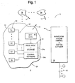
- Fig. 1 illustrates a system 10 in accordance with the invention.
- the system 10 includes a plurality of detectors D1, D2 ... Dm which can be in wired or wireless communication via a medium such as medium 14 with a common monitoring system control unit 18.
- the control unit 18 could be implemented with one or more programmable processors as well as associated system software.
- the monitoring system 18 also includes a plurality of alarm indicating output devices 20 as would be understood by those of skill in the art.
- the members of the plurality Di are substantially identical and a discussion of detector D1 will suffice as a description of other members of the plurality.
- the detector D1 is carried in a housing 26 which could be installed anywhere in a region R being monitored.
- Detector D1 includes a plurality of ambient condition sensors 30.
- the sensors 30 include a primary sensor Sp, and one or more secondary sensors S1, S2 ... Sn.
- the sensors 30 can be selected from a class which includes photoelectric smoke sensors, ionization-type smoke sensors, infrared fire sensors, gas sensors (such as carbon monoxide sensors), thermal sensors all without limitation.
- Signals 32 from the sensors 30 can be coupled to local control circuitry 34 in housing 26.
- Control circuitry 34 could be implemented with a programmable processor 34a and associated control software 34b. Those of skill will understand that the details of processor 34a and control software 34b, except as described subsequently, are not limitations of the present invention.
- the detectors Di such as detector D1, can communicate via wired or wireless interface circuitry 40 via the medium 14 which could be both wired and wireless (with the monitoring system 18).
- the control circuitry 34b can include processing functionality to evaluate a cross-correlation function based on outputs or signals from the secondary sensors, S1, S2 ... Sn.
- the cross-correlation function which can incorporate combining output signals from the secondary sensors, such as S1 and S2 by multiplication or addition, can subsequently used to change a threshold value to which an output signal from the primary sensor Sp is compared.
- the above-described processing can be carried out solely within each of the detectors Di, entirely at the monitoring system 18, or, partially at the respective detector and partially at the monitoring system 18 all without limitation. It will also understand that the monitoring system 18 can download on a dynamic basis via the medium 14, commands or additional control software to modify the cross-correlation processing in response to signal values being received from one or more of the sensors 30.
- the outputs from the primary sensor Sp which is a photoelectric sensor, can be compared to dynamically altered alarm threshold values based on processed outputs of one or more of the secondary sensors such as thermal sensors, gas sensors or infrared sensors.
- a fire which is generating gas, producing increased temperature and emitting infrared radiation, can result in the processing, carried out for example, at detector D1 via control software 34b to reduce the sensitivity of the primary sensor to a relatively low value of .2%/ft from a normal value of 3%/ft for conditions that do not generate those increased levels of gas, temperature or infrared radiation. This substantially shortens the time period for detection of such fires.
- Fig. 2 illustrates a flow diagram of a process 100 which could be carried out locally at the respective detector Di, as discussed above.
- the processing 100 reflects a detector which incorporates as a primary sensor, a photoelectric sensor (P) and three secondary sensors, S1, S2, S3, a thermal sensor with an output T, a carbon monoxide sensor with an output CO and a flame sensor with an output F.
- P photoelectric sensor
- the control software 34b can acquire signal values from the primary sensor Sp, and the secondary sensors S1, S2, S3 of types described above.
- the control software 34b also has available an existing threshold value TH and an OFFSET.
- the output of the flame sensor F could be processed as would be understood by those of skill in the art to determine a flame related signal PD.
- the control software 34b can be maintaining running averages of signal values from the primary sensor Sp as well as secondary thermal and gas sensors.
- the variation from respective average values for the photoelectric sensor, the thermal sensor and the gas sensor can be determined.
- step 108 If the variation of the photosensor output from the averaged photosensor output value exceeds a predetermined minimum value, step 108, then in step 110 a cross-correlation adjustment value is established for purposes of modifying the threshold value TH. Executing step 108 minimizes the likelihood of nuisance or false alarms in that the output from the primary sensor Sp is required to vary from its running average by the predetermined amount before an alarm determination is carried out.
- step 110 In the presence of a significant enough variation of the signal from the primary sensor from its average value, an adjustment value is established as illustrated in step 110.
- step 112 the variation of the primary sensor Sp is compared to an adjusted threshold value.
- step 114 If the variation in signal from the primary sensor from its average value, exceeds the adjusted threshold value, an alarm condition is indicated, step 114.
- the alarm condition can be forwarded via medium 14 to the monitoring system 18 for further processing and generation of alarm indicating outputs as needed. Alternately, where no alarm condition has been established, step 116, the control software 34b continues evaluating outputs from the detectors 30.
- Fig. 3 is a graph illustrating some of the aspects of the results of the method 100.
- the alarm threshold TH associated with the primary sensor Sp was substantially constant at TH1.
- the output signal from the primary sensor Sp, as well as the output signals from the secondary sensors, thermal sensor S1, and gas sensor S2 all start to increase.
- the threshold value for the primary sensor falls from the initial TH1 to a lesser value TH2 in response to the increase in value of the adj function.
- step 114 The time to entering an alarm state, step 114, can thus be substantially shortened in comparison to a condition where the alarm threshold is not altered. Additionally, because the adjustment function Adj responds to at least the thermal signals and gas signals from the respective secondary sensors, these provide supporting indicia that an ongoing fire process may well be present and developing as opposed to a false alarm.
Landscapes
- Physics & Mathematics (AREA)
- General Physics & Mathematics (AREA)
- Engineering & Computer Science (AREA)
- Computer Security & Cryptography (AREA)
- Business, Economics & Management (AREA)
- Emergency Management (AREA)
- Fire Alarms (AREA)
- Fire-Detection Mechanisms (AREA)
Claims (9)
- Système de détection d'incendie, comprenant :une pluralité de détecteurs, chacun des détecteurs comprenant :au moins trois capteurs de condition ambiante différents, un des capteurs est un capteur de condition primaire, les autres sont des capteurs de condition secondaire, tous les capteurs produisent des sorties indiquant des conditions respectives ;un circuit de commande qui définit un seuil d'alarme variable avec le temps pour le capteur de condition primaire, le circuit de commande réagit à des sorties des deux capteurs secondaires pour former un indice d'ajustement de seuil de corrélation croisée, le circuit de commande incluant en outre un circuit pour ajuster le seuil d'alarme variable avec le temps en accord avec l'indice fourni que la sortie du capteur primaire a dépassé une valeur prédéterminée ; etun circuit de détermination d'alarme réagissant au seuil ajusté variable avec le temps lorsque la sortie du capteur primaire est au-dessus dudit seuil ajusté, et le système de détection comprend en outre :un système de surveillance qui surveille la pluralité de détecteurs, le système de surveillance charge sur une base dynamique des commandes pour modifier le processus de corrélation croisée de chacun de la pluralité de détecteurs en réponse à des valeurs de signaux reçues d'un ou de plusieurs capteurs de l'élément respectif de la pluralité de détecteurs, où au moins un des détecteurs comprend un capteur photoélectrique comme capteur de condition primaire, et les capteurs de condition secondaire comprennent un capteur infrarouge et un capteur thermique, le capteur infrarouge, en réponse à la détection de flammes, est apte à réduire un seuil associé au capteur thermique, en lui permettant d'apporter une plus grande contribution au résultat de corrélation croisée, ce qui, à son tour, diminuera le seuil d'alarme du capteur photoélectrique primaire.
- Système de détection selon la revendication 1, dans lequel chaque détecteur comprend un circuit pour former une moyenne de fonctionnement d'au moins la sortie du capteur primaire, où une représentation de courant de la sortie du capteur primaire doit dépasser une valeur moyenne de courant d'une quantité prédéterminée avant de déterminer si une condition d'alarme est présente.
- Système de détection selon la revendication 1, dans lequel le circuit de commande exécute une multiplication de représentations de signaux des capteurs de condition secondaire pour former l'indice d'ajustement du seuil.
- Système de détection selon la revendication 3, dans lequel le circuit de commande divise le seuil d'alarme variable avec le temps par l'indice d'ajustement de seuil.
- Système de détection selon la revendication 1, dans lequel le circuit de commande comprend un processeur programmable et des instructions associées.
- Système de détection selon la revendication 5, dans lequel de premières instructions forment l'indice d'ajustement de seuil de corrélation croisée.
- Système de détection selon la revendication 6, dans lequel de deuxièmes instructions ajustent le seuil variable avec le temps.
- Système de détection selon la revendication 7, dans lequel les deuxièmes instructions divisent une représentation du seuil d'alarme par l'indice.
- Système de détection selon la revendication 8, qui comprend de troisièmes instructions, réagissant à la représentation divisée du seuil d'alarme pour établir une détermination d'alarme.
Applications Claiming Priority (2)
| Application Number | Priority Date | Filing Date | Title |
|---|---|---|---|
| US10/997,723 US7327247B2 (en) | 2004-11-23 | 2004-11-23 | Fire detection system and method using multiple sensors |
| PCT/US2005/032610 WO2006057694A2 (fr) | 2004-11-23 | 2005-09-13 | Systeme et procede de detection incendie utilisant plusieurs capteurs |
Publications (3)
| Publication Number | Publication Date |
|---|---|
| EP1815447A2 EP1815447A2 (fr) | 2007-08-08 |
| EP1815447A4 EP1815447A4 (fr) | 2010-05-26 |
| EP1815447B1 true EP1815447B1 (fr) | 2014-02-26 |
Family
ID=36498390
Family Applications (1)
| Application Number | Title | Priority Date | Filing Date |
|---|---|---|---|
| EP05814797.6A Expired - Lifetime EP1815447B1 (fr) | 2004-11-23 | 2005-09-13 | Systeme et procede de detection incendie utilisant plusieurs capteurs |
Country Status (7)
| Country | Link |
|---|---|
| US (1) | US7327247B2 (fr) |
| EP (1) | EP1815447B1 (fr) |
| CN (1) | CN101057265B (fr) |
| AU (1) | AU2005310056A1 (fr) |
| ES (1) | ES2452021T3 (fr) |
| NO (1) | NO20073234L (fr) |
| WO (1) | WO2006057694A2 (fr) |
Families Citing this family (37)
| Publication number | Priority date | Publication date | Assignee | Title |
|---|---|---|---|---|
| US7690837B2 (en) * | 2006-03-07 | 2010-04-06 | The Boeing Company | Method of analysis of effects of cargo fire on primary aircraft structure temperatures |
| US7804402B2 (en) * | 2007-01-26 | 2010-09-28 | Honeywell International Inc. | Fire detectors with environmental data input |
| US7642924B2 (en) * | 2007-03-02 | 2010-01-05 | Walter Kidde Portable Equipment, Inc. | Alarm with CO and smoke sensors |
| US7782197B2 (en) * | 2007-11-15 | 2010-08-24 | Honeywell International Inc. | Systems and methods of detection using fire modeling |
| US7821393B2 (en) | 2008-02-01 | 2010-10-26 | Balmart Sistemas Electronicos Y De Comunicaciones S.L. | Multivariate environmental sensing system with intelligent storage and redundant transmission pathways |
| RU2475859C2 (ru) * | 2008-06-13 | 2013-02-20 | Сименс Акциенгезелльшафт | Определение времени тревожной сигнализации сигнализатора опасности |
| US8284065B2 (en) * | 2008-10-03 | 2012-10-09 | Universal Security Instruments, Inc. | Dynamic alarm sensitivity adjustment and auto-calibrating smoke detection |
| US8766807B2 (en) * | 2008-10-03 | 2014-07-01 | Universal Security Instruments, Inc. | Dynamic alarm sensitivity adjustment and auto-calibrating smoke detection |
| CN101741578B (zh) * | 2008-11-19 | 2013-04-24 | 英业达股份有限公司 | 用于测试监控单元的测试方法及其服务器与测试系统 |
| US8232884B2 (en) | 2009-04-24 | 2012-07-31 | Gentex Corporation | Carbon monoxide and smoke detectors having distinct alarm indications and a test button that indicates improper operation |
| US8836532B2 (en) * | 2009-07-16 | 2014-09-16 | Gentex Corporation | Notification appliance and method thereof |
| DE102010015467B4 (de) * | 2010-04-16 | 2012-09-27 | Winrich Hoseit | Brandmelder zur Überwachung eines Raumes |
| US8547238B2 (en) * | 2010-06-30 | 2013-10-01 | Knowflame, Inc. | Optically redundant fire detector for false alarm rejection |
| US8395501B2 (en) | 2010-11-23 | 2013-03-12 | Universal Security Instruments, Inc. | Dynamic alarm sensitivity adjustment and auto-calibrating smoke detection for reduced resource microprocessors |
| US9140646B2 (en) | 2012-04-29 | 2015-09-22 | Valor Fire Safety, Llc | Smoke detector with external sampling volume using two different wavelengths and ambient light detection for measurement correction |
| US8907802B2 (en) | 2012-04-29 | 2014-12-09 | Valor Fire Safety, Llc | Smoke detector with external sampling volume and ambient light rejection |
| US8947244B2 (en) | 2012-04-29 | 2015-02-03 | Valor Fire Safety, Llc | Smoke detector utilizing broadband light, external sampling volume, and internally reflected light |
| US9330550B2 (en) | 2012-07-13 | 2016-05-03 | Walter Kidde Portable Equipment, Inc. | Low nuisance fast response hazard alarm |
| CN103152383B (zh) * | 2013-01-25 | 2016-06-01 | 中国科学院国家天文台 | 基于gpu架构的大规模数字相关器及相关运算处理方法 |
| EP2634756A3 (fr) * | 2013-06-10 | 2013-12-04 | Siemens Aktiengesellschaft | Détecteur de fumée de tabac |
| US9368012B2 (en) * | 2013-09-20 | 2016-06-14 | Honeywell International Inc. | Detector with integrated sensor platform |
| US9007224B1 (en) | 2013-10-07 | 2015-04-14 | Google Inc. | Smart-home hazard detector providing non-alarm status signals at opportune moments |
| US9601915B2 (en) * | 2013-10-29 | 2017-03-21 | Luis Santana | Electronic safety shutoff with dual redundancy |
| WO2015065965A1 (fr) | 2013-10-30 | 2015-05-07 | Valor Fire Safety, Llc | Détecteur de fumée à volume d'échantillonnage extérieur et à rejet de lumière ambiante |
| US9799175B2 (en) | 2014-05-06 | 2017-10-24 | White Stagg, Llc | Signal device with indirect lighting signal |
| CN104820207B (zh) * | 2015-05-08 | 2017-06-27 | 中国科学院新疆天文台 | 基于fpga、gpu和cpu混合架构的实时相关器 |
| CN104990198B (zh) * | 2015-05-18 | 2017-10-31 | 广东美的制冷设备有限公司 | 一种空调器及其火灾检测控制方法和系统 |
| US10600057B2 (en) * | 2016-02-10 | 2020-03-24 | Kenexis Consulting Corporation | Evaluating a placement of optical fire detector(s) based on a plume model |
| RU2620964C1 (ru) * | 2016-02-17 | 2017-05-30 | ФЕДЕРАЛЬНОЕ ГОСУДАРСТВЕННОЕ КАЗЕННОЕ ВОЕННОЕ ОБРАЗОВАТЕЛЬНОЕ УЧРЕЖДЕНИЕ ВЫСШЕГО ОБРАЗОВАНИЯ "Военная академия Ракетных войск стратегического назначения имени Петра Великого" МИНИСТЕРСТВА ОБОРОНЫ РОССИЙСКОЙ ФЕДЕРАЦИИ | Комбинированный датчик обнаружения возгораний |
| CN107045762B (zh) * | 2017-04-14 | 2023-08-11 | 重庆和航科技股份有限公司 | 电气火灾远程监测动态预警方法及系统 |
| CN107316430A (zh) * | 2017-06-22 | 2017-11-03 | 封宇 | 配电房开闭所安全预警系统 |
| US10679483B2 (en) * | 2017-08-25 | 2020-06-09 | Eleven Eleven Technologies, Llc | Gas monitoring and alarm systems and methods |
| US12511987B2 (en) | 2017-08-25 | 2025-12-30 | Eleven Eleven Technologies, Llc | Gas monitoring and alarm systems and methods including level indicator unit |
| WO2019075110A1 (fr) | 2017-10-11 | 2019-04-18 | Oneevent Technologies, Inc. | Système de détection d'incendie |
| CN108364441B (zh) * | 2018-04-26 | 2020-07-24 | 嘉兴美年大健康管理有限公司 | 一种儿童电视观姿矫正仪 |
| CN112037360B (zh) * | 2020-08-24 | 2022-11-15 | 北京云迹科技股份有限公司 | 基于巡游机器人的灾害处理方法、装置及系统 |
| JP2023168656A (ja) * | 2022-05-16 | 2023-11-29 | 日本ドライケミカル株式会社 | 異常判別プログラム及びこれを備えた火災監視システム |
Family Cites Families (34)
| Publication number | Priority date | Publication date | Assignee | Title |
|---|---|---|---|---|
| JPS5272596A (en) * | 1975-12-15 | 1977-06-17 | Yuwa Sangyo Kk | Composite early fire detecting system and device therefor |
| KR910000246Y1 (ko) * | 1984-07-11 | 1991-01-18 | 히로시 세끼 | 복합화재 검출기 |
| JPH079680B2 (ja) * | 1985-04-01 | 1995-02-01 | ホーチキ株式会社 | アナログ火災報知装置 |
| JPH0719315B2 (ja) * | 1985-04-09 | 1995-03-06 | ホーチキ株式会社 | 火災報知装置 |
| US4639598A (en) * | 1985-05-17 | 1987-01-27 | Santa Barbara Research Center | Fire sensor cross-correlator circuit and method |
| JPS6455696A (en) | 1987-08-26 | 1989-03-02 | Hochiki Co | Fire judging device |
| CH677413A5 (fr) * | 1988-06-10 | 1991-05-15 | Cerberus Ag | |
| US4992230A (en) * | 1988-07-21 | 1991-02-12 | Sabel Plastechs, Inc. | Method for making a hollow polyethylene terephthalate blow molded article with an integral external projection such as a handle |
| FI916182A7 (fi) * | 1991-01-18 | 1992-07-19 | Hochiki Co | Kombinerad metod foer faststaellande av brand. |
| US5172096A (en) * | 1991-08-07 | 1992-12-15 | Pittway Corporation | Threshold determination apparatus and method |
| GB2259763B (en) * | 1991-09-20 | 1995-05-31 | Hochiki Co | Fire alarm system |
| US5767776A (en) * | 1996-01-29 | 1998-06-16 | Engelhard Sensor Technologies, Inc. | Fire detector |
| JP3243115B2 (ja) * | 1993-10-29 | 2002-01-07 | ホーチキ株式会社 | 光電式感知器及び火災感知システム |
| US5552763A (en) * | 1993-11-10 | 1996-09-03 | Simplex Time Recorder Company | Fire alarm system with sensitivity adjustment |
| US5483222A (en) * | 1993-11-15 | 1996-01-09 | Pittway Corporation | Multiple sensor apparatus and method |
| US5612674A (en) * | 1995-01-05 | 1997-03-18 | Pittway Corporation | High sensitivity apparatus and method with dynamic adjustment for noise |
| US5659292A (en) * | 1995-02-21 | 1997-08-19 | Pittway Corporation | Apparatus including a fire sensor and a non-fire sensor |
| US5691703A (en) * | 1995-06-07 | 1997-11-25 | Hughes Associates, Inc. | Multi-signature fire detector |
| US5557262A (en) * | 1995-06-07 | 1996-09-17 | Pittway Corporation | Fire alarm system with different types of sensors and dynamic system parameters |
| US5736928A (en) * | 1995-09-01 | 1998-04-07 | Pittway Corporation | Pre-processor apparatus and method |
| US5726633A (en) * | 1995-09-29 | 1998-03-10 | Pittway Corporation | Apparatus and method for discrimination of fire types |
| US5625342A (en) * | 1995-11-06 | 1997-04-29 | The United States Of America As Represented By The Administrator Of The National Aeronautics And Space Administration | Plural-wavelength flame detector that discriminates between direct and reflected radiation |
| US5818326A (en) * | 1996-07-02 | 1998-10-06 | Simplex Time Recorder Company | Early fire detection using temperature and smoke sensing |
| US6195011B1 (en) * | 1996-07-02 | 2001-02-27 | Simplex Time Recorder Company | Early fire detection using temperature and smoke sensing |
| US5831524A (en) * | 1997-04-29 | 1998-11-03 | Pittway Corporation | System and method for dynamic adjustment of filtering in an alarm system |
| US5995008A (en) * | 1997-05-07 | 1999-11-30 | Detector Electronics Corporation | Fire detection method and apparatus using overlapping spectral bands |
| US6114955A (en) * | 1998-06-03 | 2000-09-05 | Interactive Technologies, Inc. | System and method for antenna failure detection |
| US6229439B1 (en) * | 1998-07-22 | 2001-05-08 | Pittway Corporation | System and method of filtering |
| US6320501B1 (en) * | 1999-05-25 | 2001-11-20 | Pittway Corporation | Multiple sensor system for alarm determination with device-to-device communications |
| GB2371412A (en) * | 2001-01-17 | 2002-07-24 | Sun Microsystems Inc | Rack mountable systems with plastic slides |
| JP3972597B2 (ja) * | 2001-04-24 | 2007-09-05 | 松下電工株式会社 | 複合型火災感知器 |
| US6983153B2 (en) * | 2001-06-07 | 2006-01-03 | Qualcomm Incorporated | Method and apparatus for congestion control in a wireless communication system |
| US6788198B2 (en) * | 2002-03-12 | 2004-09-07 | Bob F. Harshaw | System for verifying detection of a fire event condition |
| US6989756B2 (en) * | 2002-06-20 | 2006-01-24 | Siemens Building Technologies, Inc. | Smoke detector maintenance indication method and apparatus |
-
2004
- 2004-11-23 US US10/997,723 patent/US7327247B2/en not_active Expired - Lifetime
-
2005
- 2005-09-13 EP EP05814797.6A patent/EP1815447B1/fr not_active Expired - Lifetime
- 2005-09-13 WO PCT/US2005/032610 patent/WO2006057694A2/fr not_active Ceased
- 2005-09-13 CN CN2005800390891A patent/CN101057265B/zh not_active Expired - Lifetime
- 2005-09-13 AU AU2005310056A patent/AU2005310056A1/en not_active Abandoned
- 2005-09-13 ES ES05814797.6T patent/ES2452021T3/es not_active Expired - Lifetime
-
2007
- 2007-06-22 NO NO20073234A patent/NO20073234L/no not_active Application Discontinuation
Also Published As
| Publication number | Publication date |
|---|---|
| NO20073234L (no) | 2007-08-22 |
| CN101057265B (zh) | 2010-10-27 |
| AU2005310056A1 (en) | 2006-06-01 |
| EP1815447A2 (fr) | 2007-08-08 |
| EP1815447A4 (fr) | 2010-05-26 |
| ES2452021T3 (es) | 2014-03-31 |
| US20060119477A1 (en) | 2006-06-08 |
| WO2006057694A3 (fr) | 2007-04-05 |
| US7327247B2 (en) | 2008-02-05 |
| CN101057265A (zh) | 2007-10-17 |
| WO2006057694A2 (fr) | 2006-06-01 |
Similar Documents
| Publication | Publication Date | Title |
|---|---|---|
| EP1815447B1 (fr) | Systeme et procede de detection incendie utilisant plusieurs capteurs | |
| US7602304B2 (en) | Multi-sensor device and methods for fire detection | |
| US5659292A (en) | Apparatus including a fire sensor and a non-fire sensor | |
| CA2679927C (fr) | Alarme dotee d'un detecteur de co2 et de fumee | |
| AU650938B2 (en) | Combined method of determining fires | |
| US5612674A (en) | High sensitivity apparatus and method with dynamic adjustment for noise | |
| CA2178779C (fr) | Dispositif pour determiner la nature d'un feu | |
| JPH09102084A (ja) | 異なる形式の火災センサを用いて火災状態を決定するシステム及び方法 | |
| GB2339946A (en) | Method of filtering a first signal dependent upon a second signal | |
| US8681011B2 (en) | Apparatus and method for detecting fires | |
| EP2638531A1 (fr) | Détecteur d'incendie | |
| JP4724397B2 (ja) | 警報装置 | |
| US7076403B2 (en) | Apparatus and method for dynamic smoothing | |
| EP1619640A1 (fr) | Detecteur de fumée à lumière diffusée | |
| JPH01251196A (ja) | 蓄積型火災警報装置 | |
| JP3319344B2 (ja) | 煙感知器及び煙感知システム | |
| JP2950876B2 (ja) | 火災感知器 | |
| JP3699774B2 (ja) | 火災警報装置 | |
| JPH05325056A (ja) | 火災報知装置 | |
| JPH09115070A (ja) | 火災警報装置 | |
| JP2659736B2 (ja) | 火災警報装置 | |
| JP2593170B2 (ja) | 火災警報装置 | |
| JPS63317899A (ja) | 火災警報装置 | |
| JPH08315270A (ja) | 煙炎複合感知器及び煙炎複合感知システム | |
| IL103094A (en) | Method and apparatus for detecting a fire condition |
Legal Events
| Date | Code | Title | Description |
|---|---|---|---|
| PUAI | Public reference made under article 153(3) epc to a published international application that has entered the european phase |
Free format text: ORIGINAL CODE: 0009012 |
|
| 17P | Request for examination filed |
Effective date: 20070618 |
|
| AK | Designated contracting states |
Kind code of ref document: A2 Designated state(s): AT BE BG CH CY CZ DE DK EE ES FI FR GB GR HU IE IS IT LI LT LU LV MC NL PL PT RO SE SI SK TR |
|
| AX | Request for extension of the european patent |
Extension state: AL BA HR MK YU |
|
| DAX | Request for extension of the european patent (deleted) | ||
| A4 | Supplementary search report drawn up and despatched |
Effective date: 20100427 |
|
| 17Q | First examination report despatched |
Effective date: 20110317 |
|
| REG | Reference to a national code |
Ref country code: DE Ref legal event code: R079 Ref document number: 602005042784 Country of ref document: DE Free format text: PREVIOUS MAIN CLASS: G08B0001000000 Ipc: G08B0017000000 |
|
| RIC1 | Information provided on ipc code assigned before grant |
Ipc: G08B 17/00 20060101AFI20131001BHEP Ipc: G08B 29/20 20060101ALI20131001BHEP |
|
| GRAP | Despatch of communication of intention to grant a patent |
Free format text: ORIGINAL CODE: EPIDOSNIGR1 |
|
| INTG | Intention to grant announced |
Effective date: 20131112 |
|
| GRAS | Grant fee paid |
Free format text: ORIGINAL CODE: EPIDOSNIGR3 |
|
| GRAA | (expected) grant |
Free format text: ORIGINAL CODE: 0009210 |
|
| AK | Designated contracting states |
Kind code of ref document: B1 Designated state(s): AT BE BG CH CY CZ DE DK EE ES FI FR GB GR HU IE IS IT LI LT LU LV MC NL PL PT RO SE SI SK TR |
|
| REG | Reference to a national code |
Ref country code: GB Ref legal event code: FG4D |
|
| REG | Reference to a national code |
Ref country code: CH Ref legal event code: EP |
|
| REG | Reference to a national code |
Ref country code: AT Ref legal event code: REF Ref document number: 653987 Country of ref document: AT Kind code of ref document: T Effective date: 20140315 |
|
| REG | Reference to a national code |
Ref country code: ES Ref legal event code: FG2A Ref document number: 2452021 Country of ref document: ES Kind code of ref document: T3 Effective date: 20140331 |
|
| REG | Reference to a national code |
Ref country code: IE Ref legal event code: FG4D |
|
| REG | Reference to a national code |
Ref country code: DE Ref legal event code: R096 Ref document number: 602005042784 Country of ref document: DE Effective date: 20140410 |
|
| REG | Reference to a national code |
Ref country code: NL Ref legal event code: VDEP Effective date: 20140226 |
|
| REG | Reference to a national code |
Ref country code: AT Ref legal event code: MK05 Ref document number: 653987 Country of ref document: AT Kind code of ref document: T Effective date: 20140226 |
|
| REG | Reference to a national code |
Ref country code: LT Ref legal event code: MG4D |
|
| PG25 | Lapsed in a contracting state [announced via postgrant information from national office to epo] |
Ref country code: IS Free format text: LAPSE BECAUSE OF FAILURE TO SUBMIT A TRANSLATION OF THE DESCRIPTION OR TO PAY THE FEE WITHIN THE PRESCRIBED TIME-LIMIT Effective date: 20140626 Ref country code: LT Free format text: LAPSE BECAUSE OF FAILURE TO SUBMIT A TRANSLATION OF THE DESCRIPTION OR TO PAY THE FEE WITHIN THE PRESCRIBED TIME-LIMIT Effective date: 20140226 |
|
| PG25 | Lapsed in a contracting state [announced via postgrant information from national office to epo] |
Ref country code: NL Free format text: LAPSE BECAUSE OF FAILURE TO SUBMIT A TRANSLATION OF THE DESCRIPTION OR TO PAY THE FEE WITHIN THE PRESCRIBED TIME-LIMIT Effective date: 20140226 Ref country code: FI Free format text: LAPSE BECAUSE OF FAILURE TO SUBMIT A TRANSLATION OF THE DESCRIPTION OR TO PAY THE FEE WITHIN THE PRESCRIBED TIME-LIMIT Effective date: 20140226 Ref country code: PT Free format text: LAPSE BECAUSE OF FAILURE TO SUBMIT A TRANSLATION OF THE DESCRIPTION OR TO PAY THE FEE WITHIN THE PRESCRIBED TIME-LIMIT Effective date: 20140626 Ref country code: CY Free format text: LAPSE BECAUSE OF FAILURE TO SUBMIT A TRANSLATION OF THE DESCRIPTION OR TO PAY THE FEE WITHIN THE PRESCRIBED TIME-LIMIT Effective date: 20140226 Ref country code: SE Free format text: LAPSE BECAUSE OF FAILURE TO SUBMIT A TRANSLATION OF THE DESCRIPTION OR TO PAY THE FEE WITHIN THE PRESCRIBED TIME-LIMIT Effective date: 20140226 Ref country code: AT Free format text: LAPSE BECAUSE OF FAILURE TO SUBMIT A TRANSLATION OF THE DESCRIPTION OR TO PAY THE FEE WITHIN THE PRESCRIBED TIME-LIMIT Effective date: 20140226 |
|
| PG25 | Lapsed in a contracting state [announced via postgrant information from national office to epo] |
Ref country code: BE Free format text: LAPSE BECAUSE OF FAILURE TO SUBMIT A TRANSLATION OF THE DESCRIPTION OR TO PAY THE FEE WITHIN THE PRESCRIBED TIME-LIMIT Effective date: 20140226 Ref country code: LV Free format text: LAPSE BECAUSE OF FAILURE TO SUBMIT A TRANSLATION OF THE DESCRIPTION OR TO PAY THE FEE WITHIN THE PRESCRIBED TIME-LIMIT Effective date: 20140226 |
|
| PG25 | Lapsed in a contracting state [announced via postgrant information from national office to epo] |
Ref country code: RO Free format text: LAPSE BECAUSE OF FAILURE TO SUBMIT A TRANSLATION OF THE DESCRIPTION OR TO PAY THE FEE WITHIN THE PRESCRIBED TIME-LIMIT Effective date: 20140226 Ref country code: DK Free format text: LAPSE BECAUSE OF FAILURE TO SUBMIT A TRANSLATION OF THE DESCRIPTION OR TO PAY THE FEE WITHIN THE PRESCRIBED TIME-LIMIT Effective date: 20140226 Ref country code: CZ Free format text: LAPSE BECAUSE OF FAILURE TO SUBMIT A TRANSLATION OF THE DESCRIPTION OR TO PAY THE FEE WITHIN THE PRESCRIBED TIME-LIMIT Effective date: 20140226 Ref country code: EE Free format text: LAPSE BECAUSE OF FAILURE TO SUBMIT A TRANSLATION OF THE DESCRIPTION OR TO PAY THE FEE WITHIN THE PRESCRIBED TIME-LIMIT Effective date: 20140226 |
|
| REG | Reference to a national code |
Ref country code: DE Ref legal event code: R097 Ref document number: 602005042784 Country of ref document: DE |
|
| PG25 | Lapsed in a contracting state [announced via postgrant information from national office to epo] |
Ref country code: SK Free format text: LAPSE BECAUSE OF FAILURE TO SUBMIT A TRANSLATION OF THE DESCRIPTION OR TO PAY THE FEE WITHIN THE PRESCRIBED TIME-LIMIT Effective date: 20140226 Ref country code: PL Free format text: LAPSE BECAUSE OF FAILURE TO SUBMIT A TRANSLATION OF THE DESCRIPTION OR TO PAY THE FEE WITHIN THE PRESCRIBED TIME-LIMIT Effective date: 20140226 |
|
| PLBE | No opposition filed within time limit |
Free format text: ORIGINAL CODE: 0009261 |
|
| STAA | Information on the status of an ep patent application or granted ep patent |
Free format text: STATUS: NO OPPOSITION FILED WITHIN TIME LIMIT |
|
| 26N | No opposition filed |
Effective date: 20141127 |
|
| REG | Reference to a national code |
Ref country code: DE Ref legal event code: R097 Ref document number: 602005042784 Country of ref document: DE Effective date: 20141127 |
|
| PG25 | Lapsed in a contracting state [announced via postgrant information from national office to epo] |
Ref country code: MC Free format text: LAPSE BECAUSE OF FAILURE TO SUBMIT A TRANSLATION OF THE DESCRIPTION OR TO PAY THE FEE WITHIN THE PRESCRIBED TIME-LIMIT Effective date: 20140226 Ref country code: LU Free format text: LAPSE BECAUSE OF FAILURE TO SUBMIT A TRANSLATION OF THE DESCRIPTION OR TO PAY THE FEE WITHIN THE PRESCRIBED TIME-LIMIT Effective date: 20140913 |
|
| REG | Reference to a national code |
Ref country code: CH Ref legal event code: PL |
|
| PG25 | Lapsed in a contracting state [announced via postgrant information from national office to epo] |
Ref country code: SI Free format text: LAPSE BECAUSE OF FAILURE TO SUBMIT A TRANSLATION OF THE DESCRIPTION OR TO PAY THE FEE WITHIN THE PRESCRIBED TIME-LIMIT Effective date: 20140226 |
|
| REG | Reference to a national code |
Ref country code: IE Ref legal event code: MM4A |
|
| PG25 | Lapsed in a contracting state [announced via postgrant information from national office to epo] |
Ref country code: CH Free format text: LAPSE BECAUSE OF NON-PAYMENT OF DUE FEES Effective date: 20140930 Ref country code: LI Free format text: LAPSE BECAUSE OF NON-PAYMENT OF DUE FEES Effective date: 20140930 |
|
| PG25 | Lapsed in a contracting state [announced via postgrant information from national office to epo] |
Ref country code: IE Free format text: LAPSE BECAUSE OF NON-PAYMENT OF DUE FEES Effective date: 20140913 |
|
| PG25 | Lapsed in a contracting state [announced via postgrant information from national office to epo] |
Ref country code: BG Free format text: LAPSE BECAUSE OF FAILURE TO SUBMIT A TRANSLATION OF THE DESCRIPTION OR TO PAY THE FEE WITHIN THE PRESCRIBED TIME-LIMIT Effective date: 20140226 |
|
| PG25 | Lapsed in a contracting state [announced via postgrant information from national office to epo] |
Ref country code: GR Free format text: LAPSE BECAUSE OF FAILURE TO SUBMIT A TRANSLATION OF THE DESCRIPTION OR TO PAY THE FEE WITHIN THE PRESCRIBED TIME-LIMIT Effective date: 20140527 |
|
| PG25 | Lapsed in a contracting state [announced via postgrant information from national office to epo] |
Ref country code: HU Free format text: LAPSE BECAUSE OF FAILURE TO SUBMIT A TRANSLATION OF THE DESCRIPTION OR TO PAY THE FEE WITHIN THE PRESCRIBED TIME-LIMIT; INVALID AB INITIO Effective date: 20050913 Ref country code: TR Free format text: LAPSE BECAUSE OF FAILURE TO SUBMIT A TRANSLATION OF THE DESCRIPTION OR TO PAY THE FEE WITHIN THE PRESCRIBED TIME-LIMIT Effective date: 20140226 |
|
| REG | Reference to a national code |
Ref country code: FR Ref legal event code: PLFP Year of fee payment: 12 |
|
| REG | Reference to a national code |
Ref country code: FR Ref legal event code: PLFP Year of fee payment: 13 |
|
| PGFP | Annual fee paid to national office [announced via postgrant information from national office to epo] |
Ref country code: IT Payment date: 20170922 Year of fee payment: 13 Ref country code: GB Payment date: 20170929 Year of fee payment: 13 |
|
| PGFP | Annual fee paid to national office [announced via postgrant information from national office to epo] |
Ref country code: ES Payment date: 20171025 Year of fee payment: 13 |
|
| REG | Reference to a national code |
Ref country code: FR Ref legal event code: PLFP Year of fee payment: 14 |
|
| GBPC | Gb: european patent ceased through non-payment of renewal fee |
Effective date: 20180913 |
|
| PG25 | Lapsed in a contracting state [announced via postgrant information from national office to epo] |
Ref country code: IT Free format text: LAPSE BECAUSE OF NON-PAYMENT OF DUE FEES Effective date: 20180913 |
|
| REG | Reference to a national code |
Ref country code: ES Ref legal event code: FD2A Effective date: 20191030 |
|
| PG25 | Lapsed in a contracting state [announced via postgrant information from national office to epo] |
Ref country code: GB Free format text: LAPSE BECAUSE OF NON-PAYMENT OF DUE FEES Effective date: 20180913 |
|
| PG25 | Lapsed in a contracting state [announced via postgrant information from national office to epo] |
Ref country code: ES Free format text: LAPSE BECAUSE OF NON-PAYMENT OF DUE FEES Effective date: 20180914 |
|
| REG | Reference to a national code |
Ref country code: DE Ref legal event code: R082 Ref document number: 602005042784 Country of ref document: DE Representative=s name: HL KEMPNER PATENTANWAELTE, SOLICITORS (ENGLAND, DE Ref country code: DE Ref legal event code: R082 Ref document number: 602005042784 Country of ref document: DE Representative=s name: HL KEMPNER PATENTANWALT, RECHTSANWALT, SOLICIT, DE Ref country code: DE Ref legal event code: R082 Ref document number: 602005042784 Country of ref document: DE Representative=s name: HL KEMPNER PARTG MBB, DE |
|
| P01 | Opt-out of the competence of the unified patent court (upc) registered |
Effective date: 20230523 |
|
| PGFP | Annual fee paid to national office [announced via postgrant information from national office to epo] |
Ref country code: DE Payment date: 20240926 Year of fee payment: 20 |
|
| PGFP | Annual fee paid to national office [announced via postgrant information from national office to epo] |
Ref country code: FR Payment date: 20240925 Year of fee payment: 20 |