EP1815448B1 - Drahtlose sensoreinrichtung - Google Patents
Drahtlose sensoreinrichtung Download PDFInfo
- Publication number
- EP1815448B1 EP1815448B1 EP05809366A EP05809366A EP1815448B1 EP 1815448 B1 EP1815448 B1 EP 1815448B1 EP 05809366 A EP05809366 A EP 05809366A EP 05809366 A EP05809366 A EP 05809366A EP 1815448 B1 EP1815448 B1 EP 1815448B1
- Authority
- EP
- European Patent Office
- Prior art keywords
- signal
- detection
- power
- electric
- threshold
- Prior art date
- Legal status (The legal status is an assumption and is not a legal conclusion. Google has not performed a legal analysis and makes no representation as to the accuracy of the status listed.)
- Ceased
Links
Images

Classifications
-
- G—PHYSICS
- G08—SIGNALLING
- G08C—TRANSMISSION SYSTEMS FOR MEASURED VALUES, CONTROL OR SIMILAR SIGNALS
- G08C17/00—Arrangements for transmitting signals characterised by the use of a wireless electrical link
-
- H—ELECTRICITY
- H04—ELECTRIC COMMUNICATION TECHNIQUE
- H04Q—SELECTING
- H04Q9/00—Arrangements in telecontrol or telemetry systems for selectively calling a substation from a main station, in which substation desired apparatus is selected for applying a control signal thereto or for obtaining measured values therefrom
-
- G—PHYSICS
- G08—SIGNALLING
- G08B—SIGNALLING SYSTEMS, e.g. PERSONAL CALLING SYSTEMS; ORDER TELEGRAPHS; ALARM SYSTEMS
- G08B13/00—Burglar, theft or intruder alarms
- G08B13/18—Actuation by interference with heat, light, or radiation of shorter wavelength; Actuation by intruding sources of heat, light, or radiation of shorter wavelength
- G08B13/189—Actuation by interference with heat, light, or radiation of shorter wavelength; Actuation by intruding sources of heat, light, or radiation of shorter wavelength using passive radiation detection systems
- G08B13/194—Actuation by interference with heat, light, or radiation of shorter wavelength; Actuation by intruding sources of heat, light, or radiation of shorter wavelength using passive radiation detection systems using image scanning and comparing systems
-
- G—PHYSICS
- G08—SIGNALLING
- G08C—TRANSMISSION SYSTEMS FOR MEASURED VALUES, CONTROL OR SIMILAR SIGNALS
- G08C17/00—Arrangements for transmitting signals characterised by the use of a wireless electrical link
- G08C17/02—Arrangements for transmitting signals characterised by the use of a wireless electrical link using a radio link
-
- H—ELECTRICITY
- H05—ELECTRIC TECHNIQUES NOT OTHERWISE PROVIDED FOR
- H05B—ELECTRIC HEATING; ELECTRIC LIGHT SOURCES NOT OTHERWISE PROVIDED FOR; CIRCUIT ARRANGEMENTS FOR ELECTRIC LIGHT SOURCES, IN GENERAL
- H05B47/00—Circuit arrangements for operating light sources in general, i.e. where the type of light source is not relevant
- H05B47/10—Controlling the light source
- H05B47/105—Controlling the light source in response to determined parameters
- H05B47/115—Controlling the light source in response to determined parameters by determining the presence or movement of objects or living beings
- H05B47/13—Controlling the light source in response to determined parameters by determining the presence or movement of objects or living beings by using passive infrared detectors
-
- H—ELECTRICITY
- H04—ELECTRIC COMMUNICATION TECHNIQUE
- H04Q—SELECTING
- H04Q2209/00—Arrangements in telecontrol or telemetry systems
- H04Q2209/40—Arrangements in telecontrol or telemetry systems using a wireless architecture
-
- H—ELECTRICITY
- H04—ELECTRIC COMMUNICATION TECHNIQUE
- H04Q—SELECTING
- H04Q2209/00—Arrangements in telecontrol or telemetry systems
- H04Q2209/80—Arrangements in the sub-station, i.e. sensing device
- H04Q2209/82—Arrangements in the sub-station, i.e. sensing device where the sensing device takes the initiative of sending data
- H04Q2209/823—Arrangements in the sub-station, i.e. sensing device where the sensing device takes the initiative of sending data where the data is sent when the measured values exceed a threshold, e.g. sending an alarm
-
- H—ELECTRICITY
- H04—ELECTRIC COMMUNICATION TECHNIQUE
- H04Q—SELECTING
- H04Q2209/00—Arrangements in telecontrol or telemetry systems
- H04Q2209/80—Arrangements in the sub-station, i.e. sensing device
- H04Q2209/88—Providing power supply at the sub-station
- H04Q2209/883—Providing power supply at the sub-station where the sensing device enters an active or inactive mode
-
- H—ELECTRICITY
- H04—ELECTRIC COMMUNICATION TECHNIQUE
- H04Q—SELECTING
- H04Q2209/00—Arrangements in telecontrol or telemetry systems
- H04Q2209/80—Arrangements in the sub-station, i.e. sensing device
- H04Q2209/88—Providing power supply at the sub-station
- H04Q2209/886—Providing power supply at the sub-station using energy harvesting, e.g. solar, wind or mechanical
-
- Y—GENERAL TAGGING OF NEW TECHNOLOGICAL DEVELOPMENTS; GENERAL TAGGING OF CROSS-SECTIONAL TECHNOLOGIES SPANNING OVER SEVERAL SECTIONS OF THE IPC; TECHNICAL SUBJECTS COVERED BY FORMER USPC CROSS-REFERENCE ART COLLECTIONS [XRACs] AND DIGESTS
- Y02—TECHNOLOGIES OR APPLICATIONS FOR MITIGATION OR ADAPTATION AGAINST CLIMATE CHANGE
- Y02B—CLIMATE CHANGE MITIGATION TECHNOLOGIES RELATED TO BUILDINGS, e.g. HOUSING, HOUSE APPLIANCES OR RELATED END-USER APPLICATIONS
- Y02B20/00—Energy efficient lighting technologies, e.g. halogen lamps or gas discharge lamps
- Y02B20/40—Control techniques providing energy savings, e.g. smart controller or presence detection
Definitions
- the present invention is directed to a wireless sensor device, and more particularly to such wireless device including a power generating element that converts an external energy into an electric power for transmitting a sensed result as a radio signal.
- US Patent Publication US 4,982,176 discloses a wireless sensor device comprising a transmitter powered by solar cells.
- Japanese Patent Publication No. 2004-24551 discloses a self-contained sensing system including a power generating means for transmitting a sensed result.
- the system includes a sensor for sensing a temperature, an acceleration, or infrared ray to give a sensor signal indicative of a sensed analog value, and an A/D converter which converts the sensor signal into digital data.
- the digital data are processed by a microprocessor so as to be transmitted through a radio transmitter as a radio signal.
- a solar cell is included as the power generating means in order to supply an operating power to the A/D converter, the microprocessor, and the radio transmitter.
- the system requires a power regulator which enables the operation only while much power is being generated at the solar cell in order to transmit a reliable sensor result.
- the radio transmitter along with the A/D converter consumes relatively large electric power, the system suggests the use of a wireless transmission technology generally known as UWB (Ultra Wide Band) transmission which operates at a low power.
- UWB Ultra Wide Band
- the wireless sensor device includes a sensor configured to sense a target object and provide a sensor signal of varying levels indicative of condition of the target object, a signal processing circuit configured to amplify the sensor signal and give an amplified electric analog signal, and a detection circuit configured to receive the amplified analog signal and provide a detection output (Dout) when the electric analog signal goes beyond a predetermined detection threshold. Also included in the device is a radio transmitter which is configured to transmit a radio detection signal (RS) in response to the detection output.
- RS radio detection signal
- the device includes a power supply configured to provide an electric power to the signal processing circuit and the radio transmitter; and a power generating element which converts an external energy into the electric power to be accumulated in the power supply.
- a controller is included to activate the radio transmitter only in response to the detection output, permitting the radio transmitter to generate the radio detection signal. Accordingly, the radio transmitter can be kept inactivated until receiving the detection output, thereby saving energy to prolong the operating life of the power supply, i.e., the device.
- the radio transmitter includes a regulator, a clock, a pulse generator, and a driver.
- the regulator is connected to receive the electric power from the power supply and is configured to supply an operating voltage for a short time period only upon receiving the detection output from the detection circuit.
- the clock is activated upon receiving the operating voltage from the regulator to provide a clock signal.
- the pulse generator is configured to generate, based upon the clock signal, short pulses identifying the presence of the detection output.
- the driver is activated upon receiving the operating voltage from the regulator to radiate the short pulses as the radio detection signal through an antenna. With this arrangement, the clock and the driver are made active only upon receiving the detection output for transmitting the radio detection signal.
- the driver which is inherently the most power consuming unit in the radio transmitter, can be kept deactivated in the absence of the detection output, whereby the radio transmitter is held in a minimum power consumption mode while not receiving the detection output, which enables to further reduce a power requirement to the device and therefore prolong the effective operating time.
- the controller may be configured to give a sleep mode of operating the signal processing circuit at a reduced power, and to shift the sleep mode to a normal mode for reliable detection once there is acknowledged a slight sign leading to the detection output.
- the signal processing circuit operates at a rated power to obtain the electric signal (Vout) of rated amplitude proportional to the rated power.
- the signal processing circuit operates at the reduced power to obtain the electric signal (Vout) of low amplitude proportional to the reduced electric power.
- the detection circuit is configured to have a wake-up threshold which is lower, i.e., stricter than the detection threshold.
- the controller is designed to switch the normal mode to the sleep mode when the electric signal (Vout) of rated amplitude becomes lower than the detection threshold, and to keep the sleep mode until the electric signal of the low amplitude goes beyond the wake-up threshold.
- the detection output (Dout) is given when the electric signal (Vout) of rated amplitude goes beyond the detection threshold in the normal mode.
- the sensor may be an infrared ray sensor for detection of a motion of the target object by monitoring a critical change of infrared ray emitted from the target object, for example, human body.
- the infrared ray sensor is configured to provide the sensor signal which varies in positive or negative directions in response to the motion of the target.
- the detection circuit is configured to have a threshold selector which provides a detection range (A1-A2) defined by upper positive and lower negative ones of said detection threshold, and also a wake-up range (B1-B2) defined by upper positive and lower negative ones of the wake-up threshold.
- the detection circuit includes a comparator unit which receives the detection range and the wake-up range selectively from the threshold generator for comparison of the analog signal with the selected one of the ranges.
- the comparator unit generates a first signal either when the electric signal (Vout) of rated amplitude goes beyond the detection range or when the electric signal (Vout) of low amplitude goes beyond said wake-up range, and otherwise generating a second signal.
- the controller is configured to select the detection range in response to the first signal, and select the wake-up range in response to the second signal.
- the detection circuit provides the detection output only upon seeing the first signal in the normal mode. Accordingly, the sensor device can successfully detect the motion of the target object using the infrared ray sensor, while saving the energy.
- the detection circuit may include an output provider which is configured to generate the detection output (Dout) when receiving the first signal from the comparator unit at an input of said output provider.
- the input is connected to the comparator unit through a switch which is controlled by the controller to close only in response to the first signal.
- the output provider is protected from generating a false detection signal in the absence of the first signal, thereby improving detection reliability.
- the controller is connected to monitor a level of the electric power accumulated in the power supply for keeping the normal mode and disabling the sleep move while the electric power is higher than a predetermined power level. That is, while sufficient power is available, the detection circuit is kept free from a shifting between the modes, and therefore can be free from being influenced by unstable circuit operation which might appear during the transient mode shifting, assuring a reliable detection.
- the senor may be defined by a photovoltaic cell which senses an illumination level on one hand and which converts light into electrical energy for accumulating electric power in the power supply.
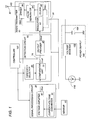
- FIG. 1 there is shown a sensor device in accordance with a preferred embodiment of the present invention.
- the device is specifically arranged to detect a human motion, i.e. whether the human comes into or out of a surveillance area by use of an infrared ray sensor which generates an electric sensor signal responsive to infrared radiation from the human, although the present invention should not be limited to this particular instance.
- the infrared ray sensor 10 generates the sensor signal which varies in positive and negative directions in response to the motion of the human coming into and out of the surveillance area.
- the device includes a signal processing circuit 20 which processes the sensor signal to give an amplified analog signal, and a detection circuit 50 which compares the analog signal with predetermined criteria to provide a detection output according to the comparison result.
- the device further includes a radio transmitter 90 which, in response to the detection output (Dout), generates and radiates a radio detection signal (RS) thorough an antenna 97 such that a receiver (not shown) acknowledge the detection result.
- a power supply 100 is included in the device to provide an electric power to the signal processing circuit 20, the detection circuit 50, and the radio transmitter 90.
- a power generating element 110 which converts an external energy into the electric power to be accumulated in the power supply 100.
- the power generating element 110 is realized in this embodiment by solar cell which converts the light into the electric power.
- a controller 120 is provided to give a consistent detection result to the radio transmitter 90 as well as to save the energy in the absence of a critical condition sensed by the sensor, the details of which will be discussed later.
- the signal processing circuit 20 is composed of a current-voltage converter 30 converting the current signal, i.e., the sensor signal output from the sensor 10 into a corresponding voltage signal, and a voltage amplifier 40 which amplifies the voltage signal into the amplified analog signal (Vout) of which amplitude varies depending upon an amplification factor instructed from the controller 120.
- the controller 120 provides a normal mode of operating the signal processing circuit 20 at a rated power, and a sleep mode of operating the signal processing circuit 20 at a reduced power for saving the energy.
- the signal processing circuit 20 operates at a high amplification factor and therefore at a high power consumption to provide the analog signal (Vout) of rated amplitude.
- the signal processing circuit 20 operates at a low amplification factor and therefore at a low power consumption to provide the analog signal (Vout) of reduced amplitude.
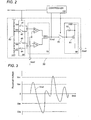
- the detector circuit 50 has a comparator unit 70 composed of comparators 71 and 72 in order to compare the analog signal (Vout) from the signal processing circuit 20 selectively with a wide detection range (VA1 to VA2) and a narrow wake-up range (VB1 to VB2) respectively defined by predetermined thresholds which are in turn defined respectively by divided voltages from a voltage dividing network 52.
- the detector circuit 50 also includes a selector 60 which is composed of switches 61 to 64 in order to give the divided voltages (VA1 and VB1) selectively to non-inverting input of the comparator 71, and give the divided voltages (VA2 and VB2) selectively to the inverting input of the comparator 72.
- the selector 60 is controlled by the controller 120 to select the detection range (VA1 to VA2) given to the comparator unit 70 in the normal mode, and select the wake-up range (VB1 to VB2) given to the comparator unit 70 in the sleep mode.
- the inverting input of the comparator 71 and the non-inverting input of the comparator 72 are commonly coupled to receive the analog signal (Vout).
- the outputs respectively from the comparators 71 and 72 are fed into an AND-gate 73 which provides a logical product of L-level output, which is referred to as a first signal in the following description, when the signal (Vout) goes beyond the detection range (VA1 to VA2) in the normal mode or beyond the wake-up range (VB1 to VB2) in the sleep mode, as shown in FIG.
- the AND-gate 73 provides a H-level output, which is referred to as a second signal.
- the controller 120 is connected to receive the output from the AND-gate 73 to select the normal mode in response to the first signal, and shift the normal mode to the sleep mode upon receiving the second signal in the normal mode for energy savings.
- the controller 120 receives the first signal from the AND-gate 83, thereby selecting the normal mode in order to compare the signal (Vout) with the detection range (VA1 to VA2).
- the AND-gate 73 is connected through a switch 76 to an output provider 80 which responds to generate the detection output (Dout).
- the switch 76 is controlled by the controller 120 to close only in response to the first signal, i.e., only when the signal (Vout) goes beyond the detection range (VA1 to VA2) in the normal mode. Otherwise, the switch 76 is kept open such that the output provider 80 gives no detection output.
- the output provider 80 includes a transistor 81 having a drain connected to a reference voltage source Vdd, and a source connected to an output terminal of the detector unit 50. A gate of the transistor 81 defines an input of the output provider 80 which is connected to receive the output from the comparator unit 70 through the switch 76.
- a pull-up resistor 82 is connected across the gate-drain path of the transistor 81 so that the transistor 81 generates the detection output (Dout) upon receiving the first signal (Vout), i.e., the H-level output from the AND-gate 73. In the absence of the first signal (Vout) fed to the gate of the transistor 81, it refrains from generating the detection output (Dout).
- the switch 76 is inserted between the AND-gate 73 and the gate of the transistor 81 in order to avoid a possibility that transistor 81 generates the detection output in the absence of the first signal.
- the switch 76 is controlled by the controller 120 to open only for a short time immediately after the controller 120 shifts the sleep mode to the normal mode and vice versa, thereby preventing the generation of the detection output (Dout) when the signal of reduced amplitude goes beyond the wake-up range in the sleep mode, and like erroneous generation of the detection output which might otherwise occur due to an abrupt voltage change possibly seen in the circuit during the transition between the two modes.
- the output provider 80 may be configured to include a noise filter which cancels the first signal generated in the wakeup mode or the like noises even when they pass through the switch 76.
- the radio transmitter 90 is configured to include a regulator 92, a clock 93, a pulse generator 94, and a driver 96.
- the regulator 92 is configured to supply a stable operating voltage V REG to the clock 93 and the driver 96 only for a short time period each upon receiving the detection output (Dout), i.e., recognition of the human presence. That is, the regulator 92 is triggered by the detection output (Dout) to supply the operating voltage V REG using a power supplied from the power supply 100, and otherwise supply no operating voltage at all.
- the clock 93 Upon receiving the operating voltage V REG , the clock 93 is activated to provide a clock signal to the pulse generator 94 which generates, based upon the clock signal, short pulses identifying the presence of the detection output with or without an address of the sensor device.
- the driver 96 which is activated by the operating voltage V REG from the regulator 92 to receive the short pulses from the pulse generator 94 and radiate the short pulses as the radio detection signal (RS) through an antenna 97.
- the radio transmitter 90 has an power input 91 through which the electric power is constantly supplied to the regulator 92 and the pulse generator 94 so that the regulator 92 and the pulse generator 94 are ready for activating the clock 93 and the driver 96 in prompt response to the detection output (Dout) from the detection circuit 50.
- the driver 96 includes an amplifier and consumes more power than any other components of the radio transmitter 90, while the pulse generator 94 and the regulator 92 in its idle mode of providing no operating voltage consume less electric power. Accordingly, in the absence of the detection output (Dout), the radio transmitter 90 consumes less power and assures prolonged operating life of the sensor device. Further, it is noted that the regulator 92 supplies the operating voltage V REG only for the short time period each time it receives the detection output (Dout), the radio transmitter 90 is reset into a low power consumption mode immediately after transmitting the radio signal (RS). The radio signal is received at a nearby receiver for recognition of the human presence or the detected result.
- the pulse generator 92 is configured to constitute a ultra wide band transmission (UWB) system, a wireless communication technology that does not use a carrier wave, but rather a train of very short pulses in the order of hundreds of picosecond range.
- the system therefore requires only a small electric power at the instant of transmitting the data.
- the data is basically composed of one-bit signal identifying whether or not the detection output (Dout) is H-level, requiring only a very short transmission time. For example, when the radio transmitter 90 transmits the radio detection signal (RS) per ten seconds, each transmission is completed within one millisecond at an average operating current of 2 mA, consuming only 0.2 ⁇ A. In this manner, the radio transmitter 90 of the UWB system can operate in a low energy consumption mode, and therefore reducing the power requirement of the sensor system.
- RS radio detection signal
- the power supply 100 is configured to have a voltage booster 102 which amplifies the voltage supplied from the solar cell 110, and a capacitor 104 accumulating the amplified voltage for supplying the resulting electric power to the signal processing circuit 20, the detection circuit 50, and the radio transmitter 90.
- the above circuits 20, 50, the radio transmitter 90, and the voltage booster 102 are each designed to operate at an average consumption current of 5 ⁇ A and to require a normal operative voltage of 4V and a minimum operating voltage of 2V. In this instance, the entire system of the sensor device consumes 10 ⁇ W to 20 ⁇ W.
- the solar cell 110 is required to have a power generating capacity of 20 ⁇ W or more, which is easy to be accomplished only with the use of an amorphouse photovoltaic cell having an effective surface area of 3 cm 2 at an illumination of about 200 lux or more.
- the sensor device can permit the use of small-sized solar cell, and is therefore assembled into a small package.
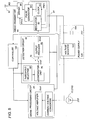
- FIG. 4 illustrates a sensor device in accordance with a second embodiment of the present invention which is identical to the above embodiment except that the controller 120 monitors the power level being generated at the solar cell 110 for comparison with a predetermined power level.
- the like parts are designated by like reference numerals, and no duplicate explanation is repeated.
- the controller 120 responds to fix the normal mode, i.e., disable the sleep mode, so as to keep the entire system awake for immediate detection. Otherwise, the controller 120 allows the shifting between the normal mode and the sleep mode for energy saving.
- FIG. 5 illustrates a sensor device in accordance with a third embodiment of the present invention which is identical to the first embodiment except that the sensor 10 is prepared as an illumination sensor made of a photovoltaic cell.
- the photovoltaic cell 10 is commonly utilized as the power generating element 110.
- Like parts are designated by like reference numerals, and no duplicated explanation is repeated here.
- the present invention should not be interpreted to be limited to the particular embodiments and can encompass any other sensor, such as a temperature sensor, vibration sensor or the like which gives the detection output when the sensed parameter exceeds a predetermined threshold or goes beyond a threshold range.
- the power generating element may be anyone that converts the external energy, such as thermal or mechanical energy into the electric power.
Landscapes
- Engineering & Computer Science (AREA)
- Computer Networks & Wireless Communication (AREA)
- Physics & Mathematics (AREA)
- General Physics & Mathematics (AREA)
- Geophysics And Detection Of Objects (AREA)
- Selective Calling Equipment (AREA)
- Arrangements For Transmission Of Measured Signals (AREA)
- Burglar Alarm Systems (AREA)
Claims (6)
- Drahtlose Sensorvorrichtung mit:einem Sensor, der so konfiguriert ist, dass er ein Zielobjekt erfasst und ein Sensorsignal mit sich ändernden Pegeln bereitstellt, die den Zustand des Zielobjekts angeben;einer Signalverarbeitungsschaltung, die so konfiguriert ist, dass sie das Sensorsignal verstärkt, um ein verstärktes analoges elektrisches Signal zu erhalten;einer Detektionsschaltung, die so konfiguriert ist, dass sie das verstärkte analoge Signal empfängt und ein Detektions-Ausgangssignal (Dout) bereitstellt, wenn das analoge elektrische Signal einen vorgegebenen Detektionsschwellenwert überschreitet;einem Funksender, der so konfiguriert ist, dass er ein Funkmesssignal (RS) in Reaktion auf das Detektions-Ausgangssignal sendet;einer Stromquelle, die so konfiguriert ist, dass sie einen elektrischen Strom für die Signalverarbeitungsschaltung, die Detektionsschaltung und den Funksender bereitstellt;
undeinem Stromerzeugungselement, das eine von außen kommende Energie in den elektrischen Strom umwandelt, um ihn in der Stromquelle zu speichern,
wobeiein Steuergerät so vorgesehen ist, dass es den Funksender nur in Reaktion auf das Detektions-Ausgangssignal aktiviert, wodurch der Funksender das Funkmesssignal erzeugen kann, unddie Vorrichtung weiterhin dadurch gekennzeichnet ist, dass der Funksender Folgendes aufweist:einen Regler, der so geschaltet ist, dass er den elektrischen Strom von der Stromquelle empfängt, und der so konfiguriert ist, dass er eine kurze Zeit lang eine Betriebsspannung nur dann erzeugt, wenn er das Detektions-Ausgangssignal (Dout) von der Detektionsschaltung empfängt;einen Taktgeber, der so konfiguriert ist, dass er bei Empfang der Betriebsspannung aktiviert wird, um ein Taktsignal bereitzustellen;einen Impulsgenerator, der so konfiguriert ist, dass er auf Grund des Taktsignals kurze Impulse erzeugt, die das Vorhandensein des Detektions-Ausgangssignals identifizieren;
undeinen Treiber, der so konfiguriert ist, dass er bei Empfang der Betriebsspannung von dem Regler so aktiviert wird, dass er die kurzen Impulse als das Funkmesssignal über eine Antenne aussendet. - Drahtlose Sensorvorrichtung nach Anspruch 1, dadurch gekennzeichnet, dass das Steuergerät so konfiguriert ist, dass es Folgendes bereitstellt:einen normalen Modus zum Betreiben der Signalverarbeitungsschaltung mit einer Nennleistung, um ein elektrisches Signal (Vout) mit einer Nennamplitude zu erhalten, die zu der elektrischen Nennleistung proportional ist; undeinen Schlafmodus zum Betreiben der Signalverarbeitungsschaltung mit einer reduzierten Leistung, um ein elektrisches Signal (Vout) mit einer kleinen Amplitude zu erhalten, die zu der reduzierten elektrischen Leistung proportional ist,
wobeidie Detektionsschaltung so konfiguriert ist, dass sie einen Weck-Schwellenwert hat, der niedriger als der Detektionsschwellenwert ist,das Steuergerät so konfiguriert ist, dass es den normalen Modus auf den Schlafmodus umschaltet, wenn das elektrische Signal (Vout) mit der Nennamplitude kleiner als der Detektionsschwellenwert wird, und den Schlafmodus so lange aufrechterhält, bis das gering verstärkte elektrische Signal den Weck-Schwellenwert überschreitet, unddie Detektionsschaltung so konfiguriert ist, dass sie das Detektions-Ausgangssignal (Dout) erzeugt, wenn das elektrische Signal (Vout) mit der Nennamplitude den Detektionsschwellenwert in dem normalen Modus überschreitet. - Drahtlose Sensorvorrichtung nach Anspruch 2, dadurch gekennzeichnet, dass
der Sensor ein Infrarotstrahlungssensor zur Detektion einer Bewegung des Zielobjekts ist, das Infrarotstrahlung erzeugt, wobei der Sensor ein Sensorsignal bereitstellt, das sich in einer positiven oder negativen Richtung in Reaktion auf die Bewegung des Zielobjekts ändert,
wobei
die Detektionsschaltung einen Schwellenwertwähler hat, der Folgendes bereitstellt:einen Detektionsbereich (A1 - A2), der durch einen oberen positiven Detektionsschwellenwert und einen unteren negativen Detektionsschwellenwert definiert ist; undeinen Weckbereich (B1 - B2), der durch einen oberen positiven und einen unteren negativen Weck-Schwellenwert definiert ist,die Detektionsschaltung eine Komparator-Einheit hat, die den Detektionsbereich und den Weckbereich selektiv von dem Schwellenwert-Generator empfängt,die Komparator-Einheit ein erstes Signal (Cout) erzeugt, wenn das elektrische Signal (Vout) mit der Nennamplitude den Detektionsbereich überschreitet oder wenn das elektrische Signal (Vout) mit der kleinen Amplitude den Weckbereich überschreitet, und andernfalls ein zweites Signal (Cout) erzeugt,das Steuergerät den Detektionsbereich in Reaktion auf das erste Signal (Cout) wählt und den Weckbereich in Reaktion auf das zweite Signal (Cout) wählt unddie Detektionsschaltung das Detektions-Ausgangssignal nur dann bereitstellt, wenn sie das erste Signal (Cout) in dem normalen Modus erkennt. - Drahtlose Sensorvorrichtung nach Anspruch 3, dadurch gekennzeichnet, dass
die Detektionsschaltung eine Ausgangssignal-Bereitstellungseinheit hat, die so konfiguriert ist, dass sie das Detektions-Ausgangssignal (Dout) erzeugt, wenn sie das erste Signal von der Komparator-Einheit an einem Eingang der Ausgangssignal-Bereitstellungseinheit empfängt, und
der Eingang so geschaltet ist, dass er das erste Signal von der Komparator-Einheit über einen Schalter empfängt, der von dem Steuergerät so gesteuert wird, dass er sich nur in Reaktion auf das erste Signal schließt. - Drahtlose Sensorvorrichtung nach Anspruch 2, dadurch gekennzeichnet, dass das Steuergerät so geschaltet ist, dass es den Pegel des in der Stromquelle gespeicherten elektrischen Stroms überwacht und den normalen Modus aufrechterhält und den Schlafinodus abschaltet, wenn der elektrische Strom größer als ein vorgegebener Strompegel ist.
- Drahtlose Sensorvorrichtung nach Anspruch 1, dadurch gekennzeichnet, dass der Sensor zum Erfassen einer Beleuchtungsstärke vorgesehen ist und von einer Fotovoltaikzelle definiert wird, die Licht in elektrische Energie umwandelt, wobei die Fotovoltaikzelle außerdem das Stromerzeugungselement zum Speichern des elektrischen Stroms in der Stromquelle definiert.
Applications Claiming Priority (2)
| Application Number | Priority Date | Filing Date | Title |
|---|---|---|---|
| JP2004341074A JP4779342B2 (ja) | 2004-11-25 | 2004-11-25 | 無線センサ装置 |
| PCT/JP2005/021640 WO2006057322A1 (en) | 2004-11-25 | 2005-11-18 | Wireless sensor device |
Publications (2)
| Publication Number | Publication Date |
|---|---|
| EP1815448A1 EP1815448A1 (de) | 2007-08-08 |
| EP1815448B1 true EP1815448B1 (de) | 2010-09-22 |
Family
ID=35601782
Family Applications (1)
| Application Number | Title | Priority Date | Filing Date |
|---|---|---|---|
| EP05809366A Ceased EP1815448B1 (de) | 2004-11-25 | 2005-11-18 | Drahtlose sensoreinrichtung |
Country Status (9)
| Country | Link |
|---|---|
| US (1) | US7792553B2 (de) |
| EP (1) | EP1815448B1 (de) |
| JP (1) | JP4779342B2 (de) |
| KR (1) | KR100819108B1 (de) |
| CN (1) | CN100489905C (de) |
| DE (1) | DE602005023767D1 (de) |
| SG (1) | SG158081A1 (de) |
| TW (1) | TWI300911B (de) |
| WO (1) | WO2006057322A1 (de) |
Families Citing this family (33)
| Publication number | Priority date | Publication date | Assignee | Title |
|---|---|---|---|---|
| JP4242335B2 (ja) * | 2004-12-06 | 2009-03-25 | 日本電信電話株式会社 | 振動起動無線装置,構造物検査システム及び構造物検査方法 |
| SE530291C2 (sv) * | 2006-09-08 | 2008-04-22 | Dick Holmen | Detektor och larmsystem för övervakning av rörliga objekt |
| JP2008099356A (ja) * | 2006-10-06 | 2008-04-24 | Seiko Instruments Inc | モード切替回路 |
| WO2009062185A2 (en) * | 2007-11-09 | 2009-05-14 | G2 Microsystems Pty. Ltd | Receiver napping during and between signal headers |
| TWI398127B (zh) * | 2008-04-08 | 2013-06-01 | Ind Tech Res Inst | 無線感測網路及其取樣頻率設定方法 |
| JP2009258063A (ja) * | 2008-04-21 | 2009-11-05 | Ohbayashi Corp | 損傷監視システム、測定装置 |
| US8629650B2 (en) | 2008-05-13 | 2014-01-14 | Qualcomm Incorporated | Wireless power transfer using multiple transmit antennas |
| US8878393B2 (en) | 2008-05-13 | 2014-11-04 | Qualcomm Incorporated | Wireless power transfer for vehicles |
| KR101380700B1 (ko) * | 2008-09-27 | 2014-04-03 | 크로마 일렉트로닉스 (센젠) 컴퍼니 리미티드 | 태양 전지 모듈을 구비한 발광소자 측정 장치 및 측정 방법 |
| US20100201312A1 (en) | 2009-02-10 | 2010-08-12 | Qualcomm Incorporated | Wireless power transfer for portable enclosures |
| US8854224B2 (en) | 2009-02-10 | 2014-10-07 | Qualcomm Incorporated | Conveying device information relating to wireless charging |
| US9312924B2 (en) | 2009-02-10 | 2016-04-12 | Qualcomm Incorporated | Systems and methods relating to multi-dimensional wireless charging |
| CN102461335B (zh) * | 2009-06-04 | 2016-03-02 | 皇家飞利浦电子股份有限公司 | 照明系统中光传感器的唤醒装置及方法 |
| US10439436B2 (en) * | 2009-07-13 | 2019-10-08 | Koninklijke Philips N.V. | Inductive power transfer |
| JP5632988B2 (ja) * | 2009-10-24 | 2014-12-03 | 国立大学法人東京農工大学 | センシングシステム |
| JP5632989B2 (ja) * | 2009-10-24 | 2014-12-03 | 国立大学法人東京農工大学 | センシング方法およびセンシングシステム |
| US20110260854A1 (en) * | 2010-04-26 | 2011-10-27 | Aikens Brian E | Power supply having a wireless transmitter |
| EP4333325B1 (de) * | 2010-09-29 | 2026-02-25 | Dexcom, Inc. | Erweitertes kontinuierliches analytüberwachungssystem |
| EP2674014B1 (de) * | 2011-02-09 | 2019-06-19 | OSRAM GmbH | Insassensensor |
| WO2012170856A1 (en) * | 2011-06-10 | 2012-12-13 | Lutron Electronics Co., Inc. | Method and apparatus for adjusting an ambient light threshold |
| JP5807871B2 (ja) * | 2011-06-27 | 2015-11-10 | セイコーインスツル株式会社 | 端末装置、通信システム及び端末装置の起動方法 |
| JP2013149093A (ja) * | 2012-01-19 | 2013-08-01 | Toshiba Corp | 制御装置、制御方法、プログラムおよび電子機器 |
| US20140001336A1 (en) * | 2012-06-27 | 2014-01-02 | Leviton Manufacturing Co., Inc. | Solar powered radio frequency transmitter |
| JP6020299B2 (ja) * | 2013-03-29 | 2016-11-02 | 三菱電機株式会社 | 無線通信装置 |
| CN104142441A (zh) * | 2013-05-10 | 2014-11-12 | 中国飞机强度研究所 | 一种系统回路线缆激励检测器 |
| WO2018066687A1 (ja) * | 2016-10-07 | 2018-04-12 | 国立大学法人電気通信大学 | 無線センサ装置及び無線センサシステム |
| EP3787507B1 (de) | 2018-05-03 | 2024-12-11 | Dexcom, Inc. | Systeme und verfahren zur aktivierung einer analyt-sensorelektronik |
| US10606549B2 (en) * | 2018-05-07 | 2020-03-31 | Spotify Ab | Automated low power mode based upon aspects associated with vehicle |
| DE102018218171A1 (de) | 2018-10-24 | 2020-04-30 | Robert Bosch Gmbh | Schaltung zur Aufbereitung eines Wake-Up-Signals |
| JP7006565B2 (ja) * | 2018-10-31 | 2022-01-24 | オムロン株式会社 | 電気機器、通信装置、および通信システム |
| CN111540185B (zh) * | 2019-11-29 | 2024-01-12 | 国网甘肃省电力公司电力科学研究院 | 一种遥控射频信号的低功耗监测及解码方法 |
| EP3958466B1 (de) * | 2020-08-18 | 2024-05-15 | Aptiv Technologies AG | Auslöseschaltung und elektronische sicherung damit |
| KR102829093B1 (ko) * | 2022-08-16 | 2025-07-03 | 주식회사 호서텔넷 | 감지 임계값들을 변경하여 오작동을 줄일 수 있는 마이크로컨트롤러 유닛과 이를 포함하는 pir 감지 장치 |
Family Cites Families (16)
| Publication number | Priority date | Publication date | Assignee | Title |
|---|---|---|---|---|
| US4703171A (en) * | 1985-11-05 | 1987-10-27 | Target Concepts Inc. | Lighting control system with infrared occupancy detector |
| FR2645304B1 (fr) * | 1989-03-28 | 1991-06-07 | Elf France | Systeme de surveillance d'installations industrielles |
| US4982176A (en) * | 1990-01-17 | 1991-01-01 | Frank Schwarz | Solar powered lighting and alarm systems activated by motion detection |
| JPH0716274B2 (ja) * | 1990-08-21 | 1995-02-22 | 国際電気株式会社 | 無線テレメータシステム |
| US5598066A (en) * | 1994-07-29 | 1997-01-28 | Heath Company | Two-level security lighting system |
| JP3433019B2 (ja) * | 1996-09-12 | 2003-08-04 | 株式会社東芝 | 移動通信機とそのバッテリセービング方法 |
| US6356741B1 (en) * | 1998-09-18 | 2002-03-12 | Allegro Microsystems, Inc. | Magnetic pole insensitive switch circuit |
| US6275712B1 (en) * | 1999-02-26 | 2001-08-14 | Nokia Mobile Phones Ltd | Mobile station control states based on available power |
| JP2001330684A (ja) * | 2000-05-22 | 2001-11-30 | Matsushita Electric Works Ltd | 赤外線検知装置及びそれを用いた負荷制御装置 |
| ATE320640T1 (de) * | 2000-07-21 | 2006-04-15 | Greatcell Solar S A | Autonome fotovoltaisch betriebene infrarrotdetektionsvorrichtung |
| JP4572496B2 (ja) * | 2000-09-08 | 2010-11-04 | パナソニック電工株式会社 | 赤外線検出装置 |
| JP2002359592A (ja) * | 2001-06-01 | 2002-12-13 | Nippon Denki Information Technology Kk | 端末装置 |
| FR2827673B1 (fr) * | 2001-07-18 | 2003-12-12 | Somfy | Procede de mesure de la lumiere exterieure pour la commande d'un moyen de protection solaire ou d'eclairage |
| TW536618B (en) * | 2001-09-10 | 2003-06-11 | Matsushita Electric Works Ltd | Object detecting device with a pyroelectric sensor |
| WO2003031924A1 (en) * | 2001-10-10 | 2003-04-17 | Ambient Control Systems, Inc. | Incrementally scanned narrow band radiation sensing of phenomenon |
| JP2004024551A (ja) | 2002-06-26 | 2004-01-29 | Renesas Technology Corp | センサシステム用半導体装置 |
-
2004
- 2004-11-25 JP JP2004341074A patent/JP4779342B2/ja not_active Expired - Fee Related
-
2005
- 2005-11-18 SG SG200907803-1A patent/SG158081A1/en unknown
- 2005-11-18 WO PCT/JP2005/021640 patent/WO2006057322A1/en not_active Ceased
- 2005-11-18 EP EP05809366A patent/EP1815448B1/de not_active Ceased
- 2005-11-18 KR KR1020067015304A patent/KR100819108B1/ko not_active Expired - Fee Related
- 2005-11-18 DE DE602005023767T patent/DE602005023767D1/de not_active Expired - Lifetime
- 2005-11-18 CN CNB2005800032035A patent/CN100489905C/zh not_active Expired - Fee Related
- 2005-11-18 US US10/586,357 patent/US7792553B2/en not_active Expired - Fee Related
- 2005-11-25 TW TW094141559A patent/TWI300911B/zh not_active IP Right Cessation
Also Published As
| Publication number | Publication date |
|---|---|
| US7792553B2 (en) | 2010-09-07 |
| US20070159235A1 (en) | 2007-07-12 |
| EP1815448A1 (de) | 2007-08-08 |
| JP4779342B2 (ja) | 2011-09-28 |
| TWI300911B (en) | 2008-09-11 |
| TW200627320A (en) | 2006-08-01 |
| CN1914652A (zh) | 2007-02-14 |
| CN100489905C (zh) | 2009-05-20 |
| KR20070047234A (ko) | 2007-05-04 |
| DE602005023767D1 (de) | 2010-11-04 |
| HK1099836A1 (zh) | 2007-08-24 |
| KR100819108B1 (ko) | 2008-04-03 |
| JP2006154963A (ja) | 2006-06-15 |
| SG158081A1 (en) | 2010-01-29 |
| WO2006057322A1 (en) | 2006-06-01 |
Similar Documents
| Publication | Publication Date | Title |
|---|---|---|
| EP1815448B1 (de) | Drahtlose sensoreinrichtung | |
| US5915417A (en) | Automatic fluid flow control apparatus | |
| US8106768B2 (en) | Method of operating a self-powered home automation sensor device for detecting the existence of and/or for measuring the intensity of a physical phenomenon | |
| US7400911B2 (en) | Wireless node and method of powering a wireless node employing ambient light to charge an energy store | |
| US7882725B2 (en) | Sensor | |
| US20080284607A1 (en) | Communication Apparatus Having Human Body Contact Sensing Function and Method Thereof | |
| US11715968B2 (en) | Hybrid electrical power supply control system for providing electrical energy to a load, as well as a corresponding method and a sensor comprising such control system | |
| CN115909622B (zh) | 低功耗智能看护系统、方法及智能门 | |
| US6677589B2 (en) | Object detecting device with a pyroelectric sensor | |
| US20160227628A1 (en) | Multi-mode control device | |
| US9660485B2 (en) | Methods and apparatus for electronic device power | |
| EP1751727B1 (de) | Drahtlose sensoren | |
| JP2004064328A (ja) | 電源電池内蔵型非接触データキャリア及びこれを用いた移動体識別システム | |
| JP2010178043A (ja) | 受信回路 | |
| WO2009150562A1 (en) | Wireless sensor device and illumination system comprising such a device | |
| HK1099836B (en) | Wireless sensor device | |
| CN215307369U (zh) | 无线遥控焊帽 | |
| US7986963B2 (en) | Wireless communication device | |
| US12408252B1 (en) | Sequential motion-responsive modular lighting system with directional communication and low-power operation | |
| KR20040085628A (ko) | 절전기능을 구비한 무선 마우스 및 그 절전방법 | |
| CN211015805U (zh) | 一种具有开关机功能的红外探测器 | |
| CN114448410A (zh) | 一种低功耗双模无线控制装置及其控制策略 | |
| KR20220026159A (ko) | 저전력 소모형 화재감지기 및 이의 전원공급장치 |
Legal Events
| Date | Code | Title | Description |
|---|---|---|---|
| PUAI | Public reference made under article 153(3) epc to a published international application that has entered the european phase |
Free format text: ORIGINAL CODE: 0009012 |
|
| 17P | Request for examination filed |
Effective date: 20060711 |
|
| AK | Designated contracting states |
Kind code of ref document: A1 Designated state(s): CH DE GB IT LI NL |
|
| DAX | Request for extension of the european patent (deleted) | ||
| RBV | Designated contracting states (corrected) |
Designated state(s): CH DE GB IT LI NL |
|
| RAP1 | Party data changed (applicant data changed or rights of an application transferred) |
Owner name: PANASONIC ELECTRIC WORKS CO., LTD. |
|
| GRAP | Despatch of communication of intention to grant a patent |
Free format text: ORIGINAL CODE: EPIDOSNIGR1 |
|
| GRAS | Grant fee paid |
Free format text: ORIGINAL CODE: EPIDOSNIGR3 |
|
| GRAA | (expected) grant |
Free format text: ORIGINAL CODE: 0009210 |
|
| AK | Designated contracting states |
Kind code of ref document: B1 Designated state(s): CH DE GB IT LI NL |
|
| REG | Reference to a national code |
Ref country code: GB Ref legal event code: FG4D |
|
| REG | Reference to a national code |
Ref country code: CH Ref legal event code: EP |
|
| REG | Reference to a national code |
Ref country code: CH Ref legal event code: NV Representative=s name: NOVAGRAAF INTERNATIONAL SA |
|
| REF | Corresponds to: |
Ref document number: 602005023767 Country of ref document: DE Date of ref document: 20101104 Kind code of ref document: P |
|
| REG | Reference to a national code |
Ref country code: NL Ref legal event code: T3 |
|
| REG | Reference to a national code |
Ref country code: CH Ref legal event code: PFA Owner name: PANASONIC ELECTRIC WORKS CO., LTD. Free format text: PANASONIC ELECTRIC WORKS CO., LTD.#1048 OAZA KADOMA#KADOMA-SHI OSAKA (JP) -TRANSFER TO- PANASONIC ELECTRIC WORKS CO., LTD.#1048 OAZA KADOMA#KADOMA-SHI OSAKA (JP) |
|
| PLBE | No opposition filed within time limit |
Free format text: ORIGINAL CODE: 0009261 |
|
| STAA | Information on the status of an ep patent application or granted ep patent |
Free format text: STATUS: NO OPPOSITION FILED WITHIN TIME LIMIT |
|
| 26N | No opposition filed |
Effective date: 20110623 |
|
| REG | Reference to a national code |
Ref country code: DE Ref legal event code: R097 Ref document number: 602005023767 Country of ref document: DE Effective date: 20110623 |
|
| PGFP | Annual fee paid to national office [announced via postgrant information from national office to epo] |
Ref country code: DE Payment date: 20151110 Year of fee payment: 11 Ref country code: IT Payment date: 20151124 Year of fee payment: 11 Ref country code: CH Payment date: 20151111 Year of fee payment: 11 Ref country code: GB Payment date: 20151118 Year of fee payment: 11 |
|
| PGFP | Annual fee paid to national office [announced via postgrant information from national office to epo] |
Ref country code: NL Payment date: 20151012 Year of fee payment: 11 |
|
| REG | Reference to a national code |
Ref country code: DE Ref legal event code: R119 Ref document number: 602005023767 Country of ref document: DE |
|
| REG | Reference to a national code |
Ref country code: CH Ref legal event code: PL |
|
| REG | Reference to a national code |
Ref country code: NL Ref legal event code: MM Effective date: 20161201 |
|
| GBPC | Gb: european patent ceased through non-payment of renewal fee |
Effective date: 20161118 |
|
| PG25 | Lapsed in a contracting state [announced via postgrant information from national office to epo] |
Ref country code: LI Free format text: LAPSE BECAUSE OF NON-PAYMENT OF DUE FEES Effective date: 20161130 Ref country code: CH Free format text: LAPSE BECAUSE OF NON-PAYMENT OF DUE FEES Effective date: 20161130 |
|
| PG25 | Lapsed in a contracting state [announced via postgrant information from national office to epo] |
Ref country code: NL Free format text: LAPSE BECAUSE OF NON-PAYMENT OF DUE FEES Effective date: 20161201 |
|
| PG25 | Lapsed in a contracting state [announced via postgrant information from national office to epo] |
Ref country code: IT Free format text: LAPSE BECAUSE OF NON-PAYMENT OF DUE FEES Effective date: 20161118 |
|
| PG25 | Lapsed in a contracting state [announced via postgrant information from national office to epo] |
Ref country code: DE Free format text: LAPSE BECAUSE OF NON-PAYMENT OF DUE FEES Effective date: 20170601 Ref country code: GB Free format text: LAPSE BECAUSE OF NON-PAYMENT OF DUE FEES Effective date: 20161118 |