EP1815486B1 - Verbindungssystem zwischen kondensator-batterien - Google Patents
Verbindungssystem zwischen kondensator-batterien Download PDFInfo
- Publication number
- EP1815486B1 EP1815486B1 EP05818285A EP05818285A EP1815486B1 EP 1815486 B1 EP1815486 B1 EP 1815486B1 EP 05818285 A EP05818285 A EP 05818285A EP 05818285 A EP05818285 A EP 05818285A EP 1815486 B1 EP1815486 B1 EP 1815486B1
- Authority
- EP
- European Patent Office
- Prior art keywords
- connection system
- protuberance
- clamping
- linking member
- protuberances
- Prior art date
- Legal status (The legal status is an assumption and is not a legal conclusion. Google has not performed a legal analysis and makes no representation as to the accuracy of the status listed.)
- Expired - Lifetime
Links
Images


Classifications
-
- H—ELECTRICITY
- H01—ELECTRIC ELEMENTS
- H01M—PROCESSES OR MEANS, e.g. BATTERIES, FOR THE DIRECT CONVERSION OF CHEMICAL ENERGY INTO ELECTRICAL ENERGY
- H01M50/00—Constructional details or processes of manufacture of the non-active parts of electrochemical cells other than fuel cells, e.g. hybrid cells
- H01M50/50—Current conducting connections for cells or batteries
- H01M50/528—Fixed electrical connections, i.e. not intended for disconnection
-
- H—ELECTRICITY
- H01—ELECTRIC ELEMENTS
- H01G—CAPACITORS; CAPACITORS, RECTIFIERS, DETECTORS, SWITCHING DEVICES, LIGHT-SENSITIVE OR TEMPERATURE-SENSITIVE DEVICES OF THE ELECTROLYTIC TYPE
- H01G2/00—Details of capacitors not covered by a single one of groups H01G4/00-H01G11/00
- H01G2/02—Mountings
- H01G2/04—Mountings specially adapted for mounting on a chassis
-
- H—ELECTRICITY
- H01—ELECTRIC ELEMENTS
- H01G—CAPACITORS; CAPACITORS, RECTIFIERS, DETECTORS, SWITCHING DEVICES, LIGHT-SENSITIVE OR TEMPERATURE-SENSITIVE DEVICES OF THE ELECTROLYTIC TYPE
- H01G9/00—Electrolytic capacitors, rectifiers, detectors, switching devices, light-sensitive or temperature-sensitive devices; Processes of their manufacture
- H01G9/004—Details
- H01G9/08—Housing; Encapsulation
-
- H—ELECTRICITY
- H01—ELECTRIC ELEMENTS
- H01G—CAPACITORS; CAPACITORS, RECTIFIERS, DETECTORS, SWITCHING DEVICES, LIGHT-SENSITIVE OR TEMPERATURE-SENSITIVE DEVICES OF THE ELECTROLYTIC TYPE
- H01G9/00—Electrolytic capacitors, rectifiers, detectors, switching devices, light-sensitive or temperature-sensitive devices; Processes of their manufacture
- H01G9/004—Details
- H01G9/14—Structural combinations or circuits for modifying, or compensating for, electric characteristics of electrolytic capacitors
-
- H—ELECTRICITY
- H01—ELECTRIC ELEMENTS
- H01M—PROCESSES OR MEANS, e.g. BATTERIES, FOR THE DIRECT CONVERSION OF CHEMICAL ENERGY INTO ELECTRICAL ENERGY
- H01M50/00—Constructional details or processes of manufacture of the non-active parts of electrochemical cells other than fuel cells, e.g. hybrid cells
- H01M50/10—Primary casings; Jackets or wrappings
-
- H—ELECTRICITY
- H01—ELECTRIC ELEMENTS
- H01M—PROCESSES OR MEANS, e.g. BATTERIES, FOR THE DIRECT CONVERSION OF CHEMICAL ENERGY INTO ELECTRICAL ENERGY
- H01M50/00—Constructional details or processes of manufacture of the non-active parts of electrochemical cells other than fuel cells, e.g. hybrid cells
- H01M50/50—Current conducting connections for cells or batteries
Definitions
- the present invention relates to a connection system between batteries or capacitor banks associated with a circuit for example of the inverter type.
- These batteries are composed of several capacitors connected by a bus formed of two thin conductor bars or plates of different polarities superimposed and separated by an insulating layer, according to the so-called busbar technology.
- Such batteries can obviously be integrated in block boxes whose function is wider, including inverter blocks to resume the example cited above.
- connection between several capacitor banks can in fact be considered as the realization of a circuit by adding portions of circuits, which can produce a generally inductive configuration, particularly because of and at the level of the links.
- Making the connection between blocks containing such batteries, because it leads to an alternation of capacitive portions and inductive portions, is in fact to build an oscillating type circuit traversed by parasitic harmonic currents that are likely to affect capacitors and reduce their life.
- EP0450122 discloses a battery of low inductance interconnection capacitors in which the interconnects are constructed as an insulated ribbon conductor.
- connection system applied to such assemblies must therefore primarily be to reduce said currents and their possible oscillations in the capacitors.
- Some types of connection between capacitive banks used so far consist of metal bars whose insulation is simply obtained by maintaining a distance between the bars, without there being consequently other insulation that the mass of air between them.
- clamping means are provided for such so that they are easily pluggable / withdrawable, in a reduced time and without using too easily dispersable parts.
- connection devices of the prior art using the laminated busbar technology discussed above that is to say grouping two conductors of the type of bars of different polarities separated by an insulating sheet
- the connection to the parts to connect is carried out so far by means of screw / nut type, the debrochability is not easy. It involves indeed complete disassembly of the bolt, which is not fast and entails a risk of loss of one of the elements.
- connection system of the invention meets the various disadvantages mentioned above, by proposing a technical solution that is both satisfactory from an electrical point of view, that is to say mainly weakly inductive, while offering a brochability / withdrawability facilitating as much as possible the work of the operators.
- This solution is more feasible at low cost, which makes it economically very interesting.
- This new solution offers the advantages of the rolled busbar technology, that is to say that it is essentially a low inductance connection, and it allows to connect and disconnect the blocks very quickly. each other because of the existence of slides that allow to insert / remove the system of the invention after a simple loosening while maintaining the clamping means in one set.
- the invention as as will be seen later, only uses elementary parts with low production costs, making the whole system inexpensive to manufacture.
- each outgrowth comprises a clamp obtained by spreading the bus bars at the end of the outgrowth by paralleling them, the slide thus constituted being sized to receive an edge zone of a parallelepiped-shaped block. an insulator of which another edge zone is inserted into the opposite homologous protuberance, said block being connected via the clamping / loosening means to the two bars of the connecting member resting on the external surfaces of the clamps, said means of tightening / loosening being located between the clamps.
- the clamping / loosening means are part of the connecting member, the two bars and the intermediate insulating block constitute a sandwich structure which participates in the sliding and is designed to ensure a good contact pressure.
- the clamping / loosening means consist of at least one screw passing through the bars and the insulating block, an insulating bushing being interposed between said screw and at least one bar of the connecting member and the bars. outgrowths that it connects.
- the screws of the clamping / loosening means are therefore not likely to cause short circuits.
- the clamping may for example be effected by means of a bolt bearing on the outer surface of the other bar, or by fixing in a thread of the latter.
- This type of fixing combined with the relative positioning and shape of the parts of the connecting member, allow easy assembly / disassembly while ensuring efficient electrical contacts.
- the two bars are serrated or serrated on their surface in contact with the bars of the protrusions.
- the tightening / loosening means to consist of two screws arranged along an axis perpendicular to the direction of the connection.
- that of the protrusion or the zone of cooperation of the connecting member with the protrusion which does not include a clamp has a transverse cut made perpendicular to the axis of the connection, in which can slide tightening / loosening means associated with each clamp.
- the clamping means then also consist of a screw and a bolt, the screw passing through one of the conductors of the clamp via an orifice equipped with a barrel insulation, and the bolt being coaxial and integral with the other conductor, the insulating barrel having a portion extending in the clamp over a length greater than the thickness of the conductor in contact with that of the clamp that the barrel passes through, portion actually inserting into the transverse cut.
- the element that passes through the branches of the clamps of the connection system of the invention therefore consists of the screw shaft, at least partially surrounded, in the inner housing of said clamp, by the isolation gun.
- the transverse cut not only allows the passage of the screw and the barrel, but also easy assembly / disassembly by guided movement in the cut after loosening the screw.
- the bolt being integral with one of the branches of each clamp, an action on the screw head, therefore at a single point, is sufficient to allow tightening / loosening.
- a rotation of a few turns is enough surplus, which makes assembly / disassembly very easy and very fast.
- the tightening / loosening assembly is finally assembled, which makes any loss of part impossible, as is the case in the first configuration.
- the isolation barrel has a portion of greater diameter than the orifice passing through the conductor of the clamp, in which the screw head bears, and which distributes the clamping pressure over a larger surface.
- the transverse cutout is provided with a length such that when the barrel comes into abutment at its blind end, the connecting member is axially centered on the protuberance of each bus.
- This cut therefore also fulfills a positioning function by allowing the immediate centering of the connection tab in the axis of the excrescences of the buses exceeding capacitive blocks to be connected.
- This cutout is finally provided to allow the translational guidance of the connecting member / protrusion, in that it is provided slightly greater than the diameter of the portion of the isolation gun that occupies it.
- the resulting guidance facilitates the task of the operator especially during editing, reducing the time of his intervention.
- the clamp may be on the protrusion, and the cut is then at the end of the connecting member.
- the clamp may be on the protrusion, and the cut is then at the end of the connecting member. The opposite is also possible.
- the connecting member comprises a first flat straight bar and a second bar whose ends are parallel and offset with respect to the central portion contiguous to the first bar, delimiting two housing end clamps parallelepipedic pace.
- the aforementioned clamping means connect the two branches of the end clamps.
- the geometrical configuration of the connecting member respects the short distance separating the conductors of "+" and "-" polarities, and makes it possible to fulfill the objective of low inductivity of this portion of the circuit.
- the bus bar bus technology which characterizes the rest of the circuit, is in fact generalized to the design of said organs of the invention.
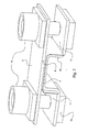
- the IGBT modules (1) and (2) together with other elements forming an inverter form a middle layer arranged between a radiator (3) for the dissipation of heat and an upper capacitive block composed of soldered electrolytic capacitors (4) or assembled to a planar plate forming a bus bar (5).
- the latter is therefore composed of two thin conductive flat bars connected to the two different polarities of the capacitors, and separated by an insulating layer.
- This bipolar bus is provided on its four sides, excrescences (6) which exceed the volume of the capacitive block and allow the connection of the inverter module to other identical modules.
- the figure 2 illustrates more clearly the shape of the protuberances (6) protruding from all sides, which are provided with a lateral slide cutout (8) for positioning the connection systems between modules (see figure 3 ), and cooperate in particular with the clamping means of said systems.
- the capacitor bank comprises twelve capacitors (4) which can be connected on at least one side, via two connection systems according to the invention, to at least one other battery also comprising twelve capacitors (4) electrolytic.
- connection system (C) appears more precisely in figure 3 . It consists, in the particular configuration illustrated in this figure, of two conductive strips (9) and (10), one of which is flat and straight (the strip 9) while the other (the strip 10) comprises a slot median which allows to offset its ends so that the connection system (C) of the invention finally has two opposing clamps between the branches of which opens a housing (11, 11 ') for the protrusions (6) protruding from the bus (5).
- An insulating layer (7) separates the bars (9, 10) in their middle portion.
- the housings (11, 11 ') are traversed by clamping means consisting of a screw (12), a bolt (13) and an insulating barrel (14).
- clamping means consisting of a screw (12), a bolt (13) and an insulating barrel (14).
- Each bolt (13) is secured to the bar (10), and the tightening of the screw (12) therefore leads to bring the two branches of each clamp.
- the head of the screw (12) is supported on a bar (9) via an enlarged portion of the insulating barrel (14), the function of which, apart from allowing this support and the guiding of the screw, mainly consists in preventing a short -circuit between the two bus bars (5) on the one hand, and the two strips (9, 10) of the connection system (C) of the invention on the other hand.
- connection system (C) makes it possible to keep the inductance at a reduced level even when several capacitive blocks are connected to each other.
- the use in these connectors of a technology that incorporates the essential principles of the one used in the bus bars / bus inside the capacitive blocks allows this low inductance connection.
- the upper diameter portion of the guide barrels (14) further allows to distribute the contact pressure between the bar (9) and the bar of the protrusion (6) which faces it and is in contact with it.
- the bar (10) a better distribution of the pressure is obtained thanks to the existence of the bolt (13) which is secured to it.
- the end clamps and the clamping means therefore have a combined action that allows good surface contact with the protuberances (6), for both polarities.
- connection / disconnection is done by a single action on each screw head (12), by a very quick and simple tightening / loosening. to perform.
- the screw which is never completely removed from the bolt, is captive, which is an additional advantage of the invention.
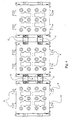
- the figure 4 gives an example of connection of several (three) inverter blocks together, using the connection systems (C) of the invention attached to each block with two screws (12). Given the existence of the protuberances (6) on the four sides of the blocks, many assembly configurations are possible.
- the cubic volume of the inverter blocks which has a double symmetry with respect to two perpendicular planes, further increases the number of possibilities of configurations in the plane.
- the figure 5 shows another possibility of configuration, according to which the clamps are arranged at the ends of the protuberances (6 ') protruding from modules for example as shown in FIG. figure 1 .
- the busbars (19, 20) of the bus are respectively stepped and flat, constituting an end slide in which an insulating block (7 ') can slide.
- the bars (9 ', 10') of the connection system (C ') also participate in the sliding, when the clamping means are in the loose position, that is to say loosened and that the bars (9', 10 ') remaining in contact with the outer surfaces, respectively upper (19) and lower (20) of the protuberances (6 ').
- the tightening / loosening means also using insulating guns (14 '), are identical to those used for the previously explained version, and therefore do not require further explanation.
- the surfaces of the bars (9 ', 10') in contact with the bars (19, 20) of the bus are notched to ensure a good connection while preserving a correct contact surface.
Landscapes
- Engineering & Computer Science (AREA)
- Power Engineering (AREA)
- Microelectronics & Electronic Packaging (AREA)
- General Chemical & Material Sciences (AREA)
- Chemical Kinetics & Catalysis (AREA)
- Electrochemistry (AREA)
- Chemical & Material Sciences (AREA)
- Connection Of Batteries Or Terminals (AREA)
- Fixed Capacitors And Capacitor Manufacturing Machines (AREA)
- Connections By Means Of Piercing Elements, Nuts, Or Screws (AREA)
- Direct Current Feeding And Distribution (AREA)
- Emergency Protection Circuit Devices (AREA)
- Dc-Dc Converters (AREA)
Claims (12)
- Verbindungssystem zwischen Kondensatorsets oder -bänken (4), die mit einem Stromkreis beispielsweise vom Wechselrichtertyp verbunden sind und dessen Kondensatoren (4) durch einen Bus (5) verbunden sind, der von zwei dünnen leitenden Schienen verschiedener Polaritäten gebildet wird, die übereinanderliegen und von einer Isolierschicht getrennt sind, dadurch gekennzeichnet, dass:- jeder Bus (5) mindestens eine Ausstülpung (6, 6') aufweist, die zur Zusammenarbeit mit einem Verbindungsorgan (C, C) zwischen zwei Ausstülpungen (6, 6') aus zwei benachbarten Kondensatorsets oder -bänken (4) vorgesehen ist,- das Verbindungsorgan zwei leitende Leisten (9, 10; 9', 10') aufweist, die vorgesehen sind, um jeweils mit den Schienen derselben Polarität von zwei gegenüberliegenden Ausstülpungen (6, 6') in Kontakt gebracht zu sein, wobei diese Leisten (9, 10; 9', 10') auf der einen und anderen Seiten einer Isolierschicht (7, 7') angeordnet sind,- eine der Ausstülpung (6, 6') oder jeder Kooperationszone des Verbindungsorgans (C, C') mit einer Ausstülpung (6, 6') eine Klemme, die eine Spannschiene bildet, aufweist, die die Positionierung der anderen durch Gleiten senkrecht zur Verbindungsachse erlaubt,- Festspann-/Lösemittel (12, 13, 14), die die Befestigung des Verbindungsorgans (C, C') an jeder Ausstülpung (6, 6') erlauben, wobei die Mittel beim Lösen in einer einzigen Gruppe bleiben.
- Verbindungssystem zwischen Kondensatorsets (4) nach vorangehendem Anspruch, dadurch gekennzeichnet, dass jede Ausstülpung (6') eine Klemme aufweist, die durch Abspreizen und paralleles Halten der Schienen (19, 20) des Busses am Ende der Ausstülpung (6') hergestellt wird, wobei die derart gebildete Spannschiene derart bemessen ist, um eine Randzone eines isolierenden parallelepipedischen Blocks (7') aufzunehmen, von dem eine andere Randzone in die entsprechende Ausstülpung (6') gegenüber einrastet, wobei der Block (7') über die Festspann-/Lösemittel mit den zwei Leisten (9', 10') des Verbindungsorgans (C) in Abstützung auf die Außenflächen der Klemmen verbunden ist, wobei die Festspann-/Lösemittel zwischen den Klemmen lokalisiert sind.
- Verbindungssystem zwischen Kondensatorsets (4) nach vorangehendem Anspruch, dadurch gekennzeichnet, dass die Festspann-/Lösemittel aus mindestens einer Schraube (12') bestehen, die die Leisten (9', 10') und den isolierenden Block (7') durchquert, wobei zwischen der Schraube (12') und mindestens einer Leiste (9') des Verbindungsorgans (C') sowie den Schienen (19) der Ausstülpungen (6'), die sie verbindet, eine isolierende Muffe (14') zwischengestellt ist.
- Verbindungssystem zwischen Kondensatorsets (4) nach vorangehendem Anspruch, dadurch gekennzeichnet, dass das Festspannen mit einem Bolzen durchgeführt wird, der sich auf der Außenfläche der anderen Leiste (20) abstützt oder durch Fixierung in einem Gewinde Letztgenannter.
- Verbindungssystem zwischen Kondensatorsets (4) nach einem der Ansprüche 3 und 4, dadurch gekennzeichnet, dass die Festspann-/Lösemittel aus zwei Schrauben (12') bestehen, die gemäß einer Achse senkrecht zur Verbindungsrichtung angeordnet sind.
- Verbindungssystem zwischen Kondensatorsets (4) nach einem der Ansprüche 2 bis 5, dadurch gekennzeichnet, dass die zwei Leisten (9', 10') auf ihrer Fläche, die mit den Schienen (19, 20) der Ausstülpungen (6') im Kontakt ist, geriffelt oder gezahnt sind.
- Verbindungssystem zwischen Kondensatorsets (4) nach Anspruch 1, dadurch gekennzeichnet, dass das der Ausstülpung (6) oder der Kooperationszone des Verbindungsorgans (C) mit der Ausstülpung (6), das keine Klemme aufweist, einen transversalen Schritt (8) senkrecht zur Verbindungsachse aufweist, in dem die Festspann-/Lösemitel (12, 14) gleiten können, die jeder Klemme zugeordnet sind.
- Verbindungssystem zwischen Kondensatorsets (4) nach vorangehendem Anspruch, dadurch gekennzeichnet, dass die Festspann-/Lösemittel aus einer Schraube (12) und einem Bolzen (13) bestehen, wobei die Schraube (12) einen der Leiter (9) der Klemme über eine Öffnung durchquert, die mit einer isolierenden Muffe (14) ausgestattet ist, und wobei der Bolzen (13) koaxial und mit dem anderen Leiter (10) verbunden ist, wobei die isolierende Muffe (14) einen Abschnitt aufweist, der sich in die Klemme über eine Länge erstreckt, die größer ist als die Dicke des Leiters im Kontakt mit dem der Klemme, den die Muffe (14) durchquert, wobei sich dieser Abschnitt in den transversalen Schnitt (8) einfügt.
- Verbindungssystem zwischen Kondensatorsets (4) nach vorangehendem Anspruch, dadurch gekennzeichnet, dass die isolierende Muffe (14) einen Durchmesserabschnitt aufweist, der größer ist als die Öffnung, die den Leiter der Klemme durchquert, in der sich der Kopf der Schraube (12) abstützt und der es erlaubt, den Festspanndruck auf eine größere Fläche zu verteilen.
- Verbindungssystem zwischen Kondensatorsets (4) nach einem der Ansprüche 8 und 9, dadurch gekennzeichnet, dass der transversale Schnitt (8) mit einer Länge vorgesehen ist, die derart ist, dass, wenn die Muffe (14) auf ihrem Blindende anschlägt, das Verbindungsorgan (C) axial auf der Ausstülpung (6) jedes Busses (5) zentriert ist.
- Verbindungssystem zwischen Kondensatorsets (4) nach einem der Ansprüche 8 bis 10, dadurch gekennzeichnet, dass die Breite des transversalen Schnitts (8) vorgesehen ist, um die verschiebende Führung des Verbindungsorgans (C) / Ausstülpung (6) zu erlauben, indem sie etwas größer vorgesehen ist als der Durchmesser des Abschnitts der isolierenden Muffe (14), der sie belegt.
- Verbindungssystem zwischen Kondensatorsets (4) nach einem der Ansprüche 7 bis 11, dadurch gekennzeichnet, dass das Verbindungsorgan (C) eine erste gerade ebene Leiste (9) aufweist und eine zweite Leiste (10), deren Enden parallel sind und im Verhältnis zum zentralen Abschnitt, der an der ersten Leiste (9) anliegt, versetzt, wobei dadurch zwei parallelepipedische Endaufnahmen (11, 11') begrenzt werden, die es erlauben, die Ausstülpungen (6) der Busse (5) aufzunehmen, die über die benachbarten Kondensatorensets (4) hinausragen, wobei die Außenflächen der Ausstülpungen (6) und die Innenflächen der Leisten (9, 10) vor dem Festspannen praktisch im Kontakt sind.
Priority Applications (1)
| Application Number | Priority Date | Filing Date | Title |
|---|---|---|---|
| PL05818285T PL1815486T3 (pl) | 2004-11-22 | 2005-11-21 | Układ połączeń baterii kondensatorów |
Applications Claiming Priority (3)
| Application Number | Priority Date | Filing Date | Title |
|---|---|---|---|
| FR0412385A FR2878368B1 (fr) | 2004-11-22 | 2004-11-22 | Systeme de connexion entre batteries de condensateurs |
| FR0502282A FR2882858B1 (fr) | 2005-03-07 | 2005-03-07 | Systeme de connexion entre batteries de condensateurs |
| PCT/FR2005/002890 WO2006053995A2 (fr) | 2004-11-22 | 2005-11-21 | Systeme de connexion entre batteries de condensateurs |
Publications (2)
| Publication Number | Publication Date |
|---|---|
| EP1815486A2 EP1815486A2 (de) | 2007-08-08 |
| EP1815486B1 true EP1815486B1 (de) | 2012-03-14 |
Family
ID=36216970
Family Applications (1)
| Application Number | Title | Priority Date | Filing Date |
|---|---|---|---|
| EP05818285A Expired - Lifetime EP1815486B1 (de) | 2004-11-22 | 2005-11-21 | Verbindungssystem zwischen kondensator-batterien |
Country Status (10)
| Country | Link |
|---|---|
| US (1) | US7667952B2 (de) |
| EP (1) | EP1815486B1 (de) |
| JP (1) | JP4785863B2 (de) |
| KR (1) | KR101082962B1 (de) |
| AT (1) | ATE549727T1 (de) |
| DK (1) | DK1815486T3 (de) |
| ES (1) | ES2385379T3 (de) |
| PL (1) | PL1815486T3 (de) |
| PT (1) | PT1815486E (de) |
| WO (1) | WO2006053995A2 (de) |
Cited By (2)
| Publication number | Priority date | Publication date | Assignee | Title |
|---|---|---|---|---|
| CN103065805A (zh) * | 2013-01-08 | 2013-04-24 | 周旺龙 | 一种矩形方块状有散热面的铝电解电容器模组及结构 |
| EP2986092A1 (de) | 2014-08-12 | 2016-02-17 | SEMIKRON Elektronik GmbH & Co. KG | Schaltschrank |
Families Citing this family (21)
| Publication number | Priority date | Publication date | Assignee | Title |
|---|---|---|---|---|
| US20080036556A1 (en) * | 2006-08-10 | 2008-02-14 | Honeywell International Inc. | Methods and apparatus for installing a feed through filter |
| US7826197B2 (en) * | 2006-11-03 | 2010-11-02 | EaglePicher Technologies | Modular energy storage device and method of making the same |
| JP5167893B2 (ja) * | 2008-03-24 | 2013-03-21 | パナソニック株式会社 | ケースモールド型コンデンサ |
| US7907385B2 (en) * | 2008-07-14 | 2011-03-15 | GM Global Technology Operations LLC | Low inductance interconnect device for a power capacitor component |
| DE102009043181A1 (de) * | 2009-09-26 | 2011-04-07 | Semikron Elektronik Gmbh & Co. Kg | Stromrichteranordnung |
| DE202010008274U1 (de) | 2010-08-12 | 2011-12-22 | Sma Solar Technology Ag | Elektrische Verbindung zwischen zwei Busbars aus ebenen Leitern und einer zwischen den Leitern angeordneten Isolationsschicht |
| CN103098519A (zh) * | 2010-09-08 | 2013-05-08 | 日本电气株式会社 | 无线通信系统、相邻小区列表优化系统、基站以及相邻小区列表更新方法 |
| DE202010008933U1 (de) | 2010-11-02 | 2010-12-23 | Sma Solar Technology Ag | Elektrische Verbindung zwischen zwei Busbars aus ebenen Leitern und einer zwischen den Leitern angeordneten Isolationsschicht |
| JP2012165611A (ja) * | 2011-02-09 | 2012-08-30 | Mitsubishi Electric Corp | 半導体ユニット及び電力変換装置 |
| DE102011015620A1 (de) * | 2011-03-31 | 2012-10-04 | Audi Ag | Batterie für ein Kraftfahrzeug und zugehöriges Herstellungsverfahren |
| US9017836B2 (en) * | 2011-07-06 | 2015-04-28 | Samsung Sdi Co., Ltd. | Battery pack |
| DE102011109609B3 (de) * | 2011-08-05 | 2013-01-17 | Peter Fischer | Verfahren zum Herstellen eines induktionsarmen Busbar |
| DE102013103866B3 (de) * | 2013-04-17 | 2014-05-22 | Semikron Elektronik Gmbh & Co. Kg | Leistungshalbleitereinrichtung |
| EP2814308B1 (de) | 2013-06-10 | 2019-06-26 | SEMIKRON Elektronik GmbH & Co. KG | 3-Level-Stromrichtereinrichtung |
| KR102073193B1 (ko) * | 2013-09-23 | 2020-02-04 | 삼성에스디아이 주식회사 | 배터리 팩 |
| DE102014201481B4 (de) * | 2014-01-28 | 2022-03-10 | Zf Friedrichshafen Ag | Schwingungsdämpfer, sowie Kolbenventil für einen Schwingungsdämpfer |
| DE102016200451B4 (de) * | 2016-01-15 | 2017-08-03 | Bayerische Motoren Werke Aktiengesellschaft | Berührgeschützte, verschraubbare elektrische Verbindung mit Toleranzausgleich |
| KR102236981B1 (ko) * | 2016-03-16 | 2021-04-05 | 엘에스엠트론 주식회사 | 에너지 저장 모듈용 연결 구조체 |
| KR101953351B1 (ko) * | 2018-08-01 | 2019-03-04 | 주식회사 이테스 | 비용접식 배터리모듈 및 이를 이용한 배터리모듈 조립체 |
| CN112768229B (zh) * | 2020-12-29 | 2022-04-29 | 南京华士电子科技有限公司 | 一种半悬空上下左右可组合的电容固定结构和方法 |
| IT202200006839A1 (it) | 2022-04-06 | 2023-10-06 | Ferrari Spa | Connettore elettrico per collegare tra loro i morsetti di due moduli batteria adiacenti in un sistema di accumulo di energia elettrica |
Family Cites Families (11)
| Publication number | Priority date | Publication date | Assignee | Title |
|---|---|---|---|---|
| JPH01181405A (ja) * | 1988-01-08 | 1989-07-19 | Sumitomo Electric Ind Ltd | コンデンサバンク |
| ATE127272T1 (de) | 1990-04-05 | 1995-09-15 | Siemens Matsushita Components | Kondensatorbatterie mit niederinduktiver verschaltung. |
| DE4439278A1 (de) * | 1994-11-03 | 1996-05-09 | Siemens Matsushita Components | Anschlußelement für elektrische Kondensatoren |
| DE19722910A1 (de) * | 1997-05-31 | 1998-12-03 | Bosch Gmbh Robert | Kondensatoranschluß, insbesondere für einen Elektrolyt-Kondensator |
| DE19725844C1 (de) * | 1997-06-18 | 1998-10-01 | Siemens Matsushita Components | Aluminium-Elektrolytkondensator mit Klemmverbindung der Anschlußelemente |
| JP4161589B2 (ja) * | 2002-02-20 | 2008-10-08 | 株式会社日立製作所 | 低電圧用コンデンサ |
| US6983443B2 (en) * | 2002-05-22 | 2006-01-03 | Agilent Technologies, Inc. | System and method for placing clock drivers in a standard cell block |
| US6845003B2 (en) * | 2002-11-29 | 2005-01-18 | Honda Motor Co., Ltd. | Metal collector foil for electric double layer capacitor, method of producing the metal collector foil, and electric double layer capacitor using the metal collector foil |
| US7307830B2 (en) * | 2003-10-10 | 2007-12-11 | Maxwell Technologies, Inc. | Capacitor with battery form factor housing |
| JPWO2005038837A1 (ja) * | 2003-10-21 | 2007-02-01 | 旭硝子株式会社 | 電気二重層キャパシタ |
| JP2006313793A (ja) * | 2005-05-06 | 2006-11-16 | Asahi Glass Co Ltd | 蓄電素子 |
-
2005
- 2005-11-21 DK DK05818285.8T patent/DK1815486T3/da active
- 2005-11-21 PL PL05818285T patent/PL1815486T3/pl unknown
- 2005-11-21 EP EP05818285A patent/EP1815486B1/de not_active Expired - Lifetime
- 2005-11-21 US US11/791,138 patent/US7667952B2/en not_active Expired - Fee Related
- 2005-11-21 WO PCT/FR2005/002890 patent/WO2006053995A2/fr not_active Ceased
- 2005-11-21 AT AT05818285T patent/ATE549727T1/de active
- 2005-11-21 ES ES05818285T patent/ES2385379T3/es not_active Expired - Lifetime
- 2005-11-21 JP JP2007544659A patent/JP4785863B2/ja not_active Expired - Fee Related
- 2005-11-21 PT PT05818285T patent/PT1815486E/pt unknown
- 2005-11-21 KR KR1020077011482A patent/KR101082962B1/ko not_active Expired - Fee Related
Cited By (5)
| Publication number | Priority date | Publication date | Assignee | Title |
|---|---|---|---|---|
| CN103065805A (zh) * | 2013-01-08 | 2013-04-24 | 周旺龙 | 一种矩形方块状有散热面的铝电解电容器模组及结构 |
| CN103065805B (zh) * | 2013-01-08 | 2017-12-19 | 周旺龙 | 一种矩形方块状有散热面的铝电解电容器模组及结构 |
| EP2986092A1 (de) | 2014-08-12 | 2016-02-17 | SEMIKRON Elektronik GmbH & Co. KG | Schaltschrank |
| CN105375741A (zh) * | 2014-08-12 | 2016-03-02 | 赛米控电子股份有限公司 | 开关柜 |
| CN105375741B (zh) * | 2014-08-12 | 2019-02-22 | 赛米控电子股份有限公司 | 开关柜 |
Also Published As
| Publication number | Publication date |
|---|---|
| PT1815486E (pt) | 2012-06-25 |
| KR20070091277A (ko) | 2007-09-10 |
| US7667952B2 (en) | 2010-02-23 |
| WO2006053995A2 (fr) | 2006-05-26 |
| JP4785863B2 (ja) | 2011-10-05 |
| ES2385379T3 (es) | 2012-07-24 |
| WO2006053995A3 (fr) | 2006-11-16 |
| EP1815486A2 (de) | 2007-08-08 |
| DK1815486T3 (da) | 2012-07-09 |
| PL1815486T3 (pl) | 2013-03-29 |
| ATE549727T1 (de) | 2012-03-15 |
| KR101082962B1 (ko) | 2011-11-11 |
| US20080002328A1 (en) | 2008-01-03 |
| JP2008521382A (ja) | 2008-06-19 |
Similar Documents
| Publication | Publication Date | Title |
|---|---|---|
| EP1815486B1 (de) | Verbindungssystem zwischen kondensator-batterien | |
| EP2495832B1 (de) | Stromleiter | |
| FR3094578A1 (fr) | Dispositif de connexion de puissance pour batterie électrique et ensemble de connexion comprenant ce dispositif. | |
| FR3047117A1 (fr) | Unite de composant electronique et boitier de connexion electrique | |
| EP2409554B1 (de) | Gehäuse, elektrischer anschluss damit und fahrzeug mit dem anschluss | |
| FR2787251A1 (fr) | Barre pour canalisation de distribution electrique | |
| FR2977366A1 (fr) | Bloc de fusible et boitier de raccordement electrique comportant ce dernier | |
| CA2348111A1 (fr) | Dispositif a contacts multiples pour les systemes de barres de bus de puissance | |
| EP0237388B1 (de) | Speise- oder Überbrückungsgerät für nebeneinander stehende elektrische Einrichtungen | |
| EP0004266B1 (de) | Halterzusammenbau für einen Sammelschienensatz | |
| FR2878368A1 (fr) | Systeme de connexion entre batteries de condensateurs | |
| FR2882858A1 (fr) | Systeme de connexion entre batteries de condensateurs | |
| EP2849295B1 (de) | Elektrische Verteilungsanordnung mit einem mehrpoligen Stromverteilungskamm. | |
| EP1422799B1 (de) | Energieverteileranordnung für elektrische Geräte | |
| FR2802024A1 (fr) | Repartiteur modulaire monopolaire et bloc de connexion pour un tel repartiteur | |
| EP2662941B1 (de) | Endeinheit für Verteilereinheit für elektrische Anlage | |
| FR2971371A1 (fr) | Connecteur modulaire et procede d'assemblage associe | |
| EP0265339B1 (de) | Elektrische Klemmleiste, Herstellungsverfahren einer solchen Leiste und elektrischer Verbinder mit einer solchen Leiste | |
| EP4162564A1 (de) | Verbindungselement zum verbinden zweier akkumulatoren | |
| EP1085553A1 (de) | Serien Herstellungsverfahren von Sicherungshaltermodule und Sicherungshaltermodule hergestellt mit diesem Verfahren | |
| EP1371113B1 (de) | Stromverbinder für eine gedruckte schaltung | |
| WO2007085746A1 (fr) | Jeu de connecteurs de raccordement electrique et procede de fabrication d'un tel connecteur | |
| FR2965675A1 (fr) | Dispositif de raccordement electrique a fusible ou barrette de sectionnement et coffret de branchement comprenant un tel dispositif. | |
| FR2802025A1 (fr) | Bloc de connexion pour repartiteur monopolaire et repartiteur monopolaire comportant un tel bloc | |
| FR3143213A1 (fr) | Ensemble de cellules d’un élément accumulateur d’énergie et procédé d’assemblage dudit ensemble |
Legal Events
| Date | Code | Title | Description |
|---|---|---|---|
| PUAI | Public reference made under article 153(3) epc to a published international application that has entered the european phase |
Free format text: ORIGINAL CODE: 0009012 |
|
| 17P | Request for examination filed |
Effective date: 20070529 |
|
| AK | Designated contracting states |
Kind code of ref document: A2 Designated state(s): AT BE BG CH CY CZ DE DK EE ES FI FR GB GR HU IE IS IT LI LT LU LV MC NL PL PT RO SE SI SK TR |
|
| DAX | Request for extension of the european patent (deleted) | ||
| GRAP | Despatch of communication of intention to grant a patent |
Free format text: ORIGINAL CODE: EPIDOSNIGR1 |
|
| RIC1 | Information provided on ipc code assigned before grant |
Ipc: H01G 9/008 20060101ALI20110916BHEP Ipc: H01G 2/04 20060101AFI20110916BHEP |
|
| GRAS | Grant fee paid |
Free format text: ORIGINAL CODE: EPIDOSNIGR3 |
|
| GRAA | (expected) grant |
Free format text: ORIGINAL CODE: 0009210 |
|
| AK | Designated contracting states |
Kind code of ref document: B1 Designated state(s): AT BE BG CH CY CZ DE DK EE ES FI FR GB GR HU IE IS IT LI LT LU LV MC NL PL PT RO SE SI SK TR |
|
| REG | Reference to a national code |
Ref country code: GB Ref legal event code: FG4D Free format text: NOT ENGLISH |
|
| REG | Reference to a national code |
Ref country code: AT Ref legal event code: REF Ref document number: 549727 Country of ref document: AT Kind code of ref document: T Effective date: 20120315 Ref country code: CH Ref legal event code: EP |
|
| REG | Reference to a national code |
Ref country code: IE Ref legal event code: FG4D Free format text: LANGUAGE OF EP DOCUMENT: FRENCH |
|
| REG | Reference to a national code |
Ref country code: DE Ref legal event code: R096 Ref document number: 602005033194 Country of ref document: DE Effective date: 20120510 |
|
| REG | Reference to a national code |
Ref country code: PT Ref legal event code: SC4A Free format text: AVAILABILITY OF NATIONAL TRANSLATION Effective date: 20120614 |
|
| REG | Reference to a national code |
Ref country code: NL Ref legal event code: T3 |
|
| REG | Reference to a national code |
Ref country code: CH Ref legal event code: PUE Owner name: SEMIKRON ELEKTRONIK GMBH & CO. KG Free format text: SEMIKRON#130 ROUTE DE CORMEILLES#78500 SARTROUVILLE (FR) -TRANSFER TO- SEMIKRON ELEKTRONIK GMBH & CO. KG#SIGMUNDSTRASSE 200#90431 NUERNBERG (DE) Ref country code: CH Ref legal event code: NV Representative=s name: BRAUNPAT BRAUN EDER AG |
|
| REG | Reference to a national code |
Ref country code: SE Ref legal event code: TRGR |
|
| REG | Reference to a national code |
Ref country code: DK Ref legal event code: T3 |
|
| REG | Reference to a national code |
Ref country code: ES Ref legal event code: FG2A Ref document number: 2385379 Country of ref document: ES Kind code of ref document: T3 Effective date: 20120724 |
|
| RAP2 | Party data changed (patent owner data changed or rights of a patent transferred) |
Owner name: SEMIKRON ELEKTRONIK GMBH & CO. KG |
|
| PG25 | Lapsed in a contracting state [announced via postgrant information from national office to epo] |
Ref country code: LT Free format text: LAPSE BECAUSE OF FAILURE TO SUBMIT A TRANSLATION OF THE DESCRIPTION OR TO PAY THE FEE WITHIN THE PRESCRIBED TIME-LIMIT Effective date: 20120314 |
|
| LTIE | Lt: invalidation of european patent or patent extension |
Effective date: 20120314 |
|
| PG25 | Lapsed in a contracting state [announced via postgrant information from national office to epo] |
Ref country code: LV Free format text: LAPSE BECAUSE OF FAILURE TO SUBMIT A TRANSLATION OF THE DESCRIPTION OR TO PAY THE FEE WITHIN THE PRESCRIBED TIME-LIMIT Effective date: 20120314 Ref country code: GR Free format text: LAPSE BECAUSE OF FAILURE TO SUBMIT A TRANSLATION OF THE DESCRIPTION OR TO PAY THE FEE WITHIN THE PRESCRIBED TIME-LIMIT Effective date: 20120615 |
|
| PG25 | Lapsed in a contracting state [announced via postgrant information from national office to epo] |
Ref country code: CY Free format text: LAPSE BECAUSE OF FAILURE TO SUBMIT A TRANSLATION OF THE DESCRIPTION OR TO PAY THE FEE WITHIN THE PRESCRIBED TIME-LIMIT Effective date: 20120314 |
|
| REG | Reference to a national code |
Ref country code: GB Ref legal event code: 732E Free format text: REGISTERED BETWEEN 20120927 AND 20121003 |
|
| PG25 | Lapsed in a contracting state [announced via postgrant information from national office to epo] |
Ref country code: SI Free format text: LAPSE BECAUSE OF FAILURE TO SUBMIT A TRANSLATION OF THE DESCRIPTION OR TO PAY THE FEE WITHIN THE PRESCRIBED TIME-LIMIT Effective date: 20120314 Ref country code: IS Free format text: LAPSE BECAUSE OF FAILURE TO SUBMIT A TRANSLATION OF THE DESCRIPTION OR TO PAY THE FEE WITHIN THE PRESCRIBED TIME-LIMIT Effective date: 20120714 Ref country code: RO Free format text: LAPSE BECAUSE OF FAILURE TO SUBMIT A TRANSLATION OF THE DESCRIPTION OR TO PAY THE FEE WITHIN THE PRESCRIBED TIME-LIMIT Effective date: 20120314 Ref country code: EE Free format text: LAPSE BECAUSE OF FAILURE TO SUBMIT A TRANSLATION OF THE DESCRIPTION OR TO PAY THE FEE WITHIN THE PRESCRIBED TIME-LIMIT Effective date: 20120314 |
|
| REG | Reference to a national code |
Ref country code: PT Ref legal event code: PC4A Owner name: SEMIKRON ELEKTRONIK GMBH & CO. KG, DE Effective date: 20121105 |
|
| REG | Reference to a national code |
Ref country code: NL Ref legal event code: SD Effective date: 20121220 |
|
| PLBE | No opposition filed within time limit |
Free format text: ORIGINAL CODE: 0009261 |
|
| STAA | Information on the status of an ep patent application or granted ep patent |
Free format text: STATUS: NO OPPOSITION FILED WITHIN TIME LIMIT |
|
| 26N | No opposition filed |
Effective date: 20121217 |
|
| REG | Reference to a national code |
Ref country code: SK Ref legal event code: T3 Ref document number: E 13007 Country of ref document: SK |
|
| REG | Reference to a national code |
Ref country code: PL Ref legal event code: T3 |
|
| REG | Reference to a national code |
Ref country code: DE Ref legal event code: R097 Ref document number: 602005033194 Country of ref document: DE Effective date: 20121217 |
|
| REG | Reference to a national code |
Ref country code: FR Ref legal event code: TP Owner name: SEMIKRON ELEKTRONIK GMBH & CO.KG, DE Effective date: 20130417 |
|
| REG | Reference to a national code |
Ref country code: HU Ref legal event code: AG4A Ref document number: E014946 Country of ref document: HU |
|
| REG | Reference to a national code |
Ref country code: AT Ref legal event code: PC Ref document number: 549727 Country of ref document: AT Kind code of ref document: T Owner name: SEMIKRON ELEKTRONIK GMBH & CO. KG, DE Effective date: 20130419 |
|
| PG25 | Lapsed in a contracting state [announced via postgrant information from national office to epo] |
Ref country code: BG Free format text: LAPSE BECAUSE OF FAILURE TO SUBMIT A TRANSLATION OF THE DESCRIPTION OR TO PAY THE FEE WITHIN THE PRESCRIBED TIME-LIMIT Effective date: 20120614 |
|
| REG | Reference to a national code |
Ref country code: IE Ref legal event code: MM4A |
|
| PG25 | Lapsed in a contracting state [announced via postgrant information from national office to epo] |
Ref country code: IE Free format text: LAPSE BECAUSE OF NON-PAYMENT OF DUE FEES Effective date: 20121121 |
|
| PG25 | Lapsed in a contracting state [announced via postgrant information from national office to epo] |
Ref country code: PL Free format text: LAPSE BECAUSE OF NON-PAYMENT OF DUE FEES Effective date: 20121121 |
|
| REG | Reference to a national code |
Ref country code: PL Ref legal event code: LAPE |
|
| PG25 | Lapsed in a contracting state [announced via postgrant information from national office to epo] |
Ref country code: MC Free format text: LAPSE BECAUSE OF NON-PAYMENT OF DUE FEES Effective date: 20121130 Ref country code: TR Free format text: LAPSE BECAUSE OF FAILURE TO SUBMIT A TRANSLATION OF THE DESCRIPTION OR TO PAY THE FEE WITHIN THE PRESCRIBED TIME-LIMIT Effective date: 20120314 |
|
| PG25 | Lapsed in a contracting state [announced via postgrant information from national office to epo] |
Ref country code: LU Free format text: LAPSE BECAUSE OF NON-PAYMENT OF DUE FEES Effective date: 20121121 |
|
| REG | Reference to a national code |
Ref country code: FR Ref legal event code: PLFP Year of fee payment: 11 |
|
| REG | Reference to a national code |
Ref country code: FR Ref legal event code: PLFP Year of fee payment: 12 |
|
| PGFP | Annual fee paid to national office [announced via postgrant information from national office to epo] |
Ref country code: CZ Payment date: 20161114 Year of fee payment: 12 Ref country code: HU Payment date: 20161109 Year of fee payment: 12 Ref country code: NL Payment date: 20161124 Year of fee payment: 12 Ref country code: FI Payment date: 20161123 Year of fee payment: 12 Ref country code: DK Payment date: 20161124 Year of fee payment: 12 Ref country code: SK Payment date: 20161111 Year of fee payment: 12 |
|
| PGFP | Annual fee paid to national office [announced via postgrant information from national office to epo] |
Ref country code: BE Payment date: 20161124 Year of fee payment: 12 Ref country code: SE Payment date: 20161124 Year of fee payment: 12 Ref country code: AT Payment date: 20161122 Year of fee payment: 12 Ref country code: PT Payment date: 20161118 Year of fee payment: 12 |
|
| REG | Reference to a national code |
Ref country code: FR Ref legal event code: PLFP Year of fee payment: 13 |
|
| REG | Reference to a national code |
Ref country code: CH Ref legal event code: PCAR Free format text: NEW ADDRESS: HOLEESTRASSE 87, 4054 BASEL (CH) |
|
| REG | Reference to a national code |
Ref country code: DK Ref legal event code: EBP Effective date: 20171130 |
|
| REG | Reference to a national code |
Ref country code: SE Ref legal event code: EUG |
|
| REG | Reference to a national code |
Ref country code: NL Ref legal event code: MM Effective date: 20171201 |
|
| REG | Reference to a national code |
Ref country code: AT Ref legal event code: MM01 Ref document number: 549727 Country of ref document: AT Kind code of ref document: T Effective date: 20171121 |
|
| PG25 | Lapsed in a contracting state [announced via postgrant information from national office to epo] |
Ref country code: SK Free format text: LAPSE BECAUSE OF NON-PAYMENT OF DUE FEES Effective date: 20171121 Ref country code: CZ Free format text: LAPSE BECAUSE OF NON-PAYMENT OF DUE FEES Effective date: 20171121 Ref country code: PT Free format text: LAPSE BECAUSE OF NON-PAYMENT OF DUE FEES Effective date: 20180521 Ref country code: FI Free format text: LAPSE BECAUSE OF NON-PAYMENT OF DUE FEES Effective date: 20171121 |
|
| REG | Reference to a national code |
Ref country code: SK Ref legal event code: MM4A Ref document number: E 13007 Country of ref document: SK Effective date: 20171121 |
|
| PG25 | Lapsed in a contracting state [announced via postgrant information from national office to epo] |
Ref country code: SE Free format text: LAPSE BECAUSE OF NON-PAYMENT OF DUE FEES Effective date: 20171122 Ref country code: HU Free format text: LAPSE BECAUSE OF NON-PAYMENT OF DUE FEES Effective date: 20171122 Ref country code: AT Free format text: LAPSE BECAUSE OF NON-PAYMENT OF DUE FEES Effective date: 20171121 |
|
| REG | Reference to a national code |
Ref country code: BE Ref legal event code: MM Effective date: 20171130 |
|
| PG25 | Lapsed in a contracting state [announced via postgrant information from national office to epo] |
Ref country code: NL Free format text: LAPSE BECAUSE OF NON-PAYMENT OF DUE FEES Effective date: 20171201 |
|
| PG25 | Lapsed in a contracting state [announced via postgrant information from national office to epo] |
Ref country code: DK Free format text: LAPSE BECAUSE OF NON-PAYMENT OF DUE FEES Effective date: 20171130 Ref country code: BE Free format text: LAPSE BECAUSE OF NON-PAYMENT OF DUE FEES Effective date: 20171130 |
|
| PGFP | Annual fee paid to national office [announced via postgrant information from national office to epo] |
Ref country code: ES Payment date: 20211216 Year of fee payment: 17 Ref country code: GB Payment date: 20211123 Year of fee payment: 17 |
|
| PGFP | Annual fee paid to national office [announced via postgrant information from national office to epo] |
Ref country code: IT Payment date: 20211130 Year of fee payment: 17 Ref country code: CH Payment date: 20211123 Year of fee payment: 17 |
|
| REG | Reference to a national code |
Ref country code: CH Ref legal event code: PL |
|
| GBPC | Gb: european patent ceased through non-payment of renewal fee |
Effective date: 20221121 |
|
| PG25 | Lapsed in a contracting state [announced via postgrant information from national office to epo] |
Ref country code: LI Free format text: LAPSE BECAUSE OF NON-PAYMENT OF DUE FEES Effective date: 20221130 Ref country code: CH Free format text: LAPSE BECAUSE OF NON-PAYMENT OF DUE FEES Effective date: 20221130 |
|
| PG25 | Lapsed in a contracting state [announced via postgrant information from national office to epo] |
Ref country code: IT Free format text: LAPSE BECAUSE OF NON-PAYMENT OF DUE FEES Effective date: 20221121 Ref country code: GB Free format text: LAPSE BECAUSE OF NON-PAYMENT OF DUE FEES Effective date: 20221121 |
|
| REG | Reference to a national code |
Ref country code: ES Ref legal event code: FD2A Effective date: 20240102 |
|
| PG25 | Lapsed in a contracting state [announced via postgrant information from national office to epo] |
Ref country code: ES Free format text: LAPSE BECAUSE OF NON-PAYMENT OF DUE FEES Effective date: 20221122 |
|
| PG25 | Lapsed in a contracting state [announced via postgrant information from national office to epo] |
Ref country code: ES Free format text: LAPSE BECAUSE OF NON-PAYMENT OF DUE FEES Effective date: 20221122 |
|
| PGFP | Annual fee paid to national office [announced via postgrant information from national office to epo] |
Ref country code: DE Payment date: 20241001 Year of fee payment: 20 |
|
| PGFP | Annual fee paid to national office [announced via postgrant information from national office to epo] |
Ref country code: FR Payment date: 20241001 Year of fee payment: 20 |
|
| REG | Reference to a national code |
Ref country code: DE Ref legal event code: R071 Ref document number: 602005033194 Country of ref document: DE |