EP1815554B1 - Lignes de couplage pour un filtre yig ou un oscillateur yig et procede pour produire ces lignes de couplage - Google Patents
Lignes de couplage pour un filtre yig ou un oscillateur yig et procede pour produire ces lignes de couplage Download PDFInfo
- Publication number
- EP1815554B1 EP1815554B1 EP05813554A EP05813554A EP1815554B1 EP 1815554 B1 EP1815554 B1 EP 1815554B1 EP 05813554 A EP05813554 A EP 05813554A EP 05813554 A EP05813554 A EP 05813554A EP 1815554 B1 EP1815554 B1 EP 1815554B1
- Authority
- EP
- European Patent Office
- Prior art keywords
- yig
- filter
- coupling
- line
- coupling line
- Prior art date
- Legal status (The legal status is an assumption and is not a legal conclusion. Google has not performed a legal analysis and makes no representation as to the accuracy of the status listed.)
- Expired - Lifetime
Links
Images
Classifications
-
- H—ELECTRICITY
- H01—ELECTRIC ELEMENTS
- H01P—WAVEGUIDES; RESONATORS, LINES, OR OTHER DEVICES OF THE WAVEGUIDE TYPE
- H01P1/00—Auxiliary devices
- H01P1/20—Frequency-selective devices, e.g. filters
- H01P1/215—Frequency-selective devices, e.g. filters using ferromagnetic material
- H01P1/218—Frequency-selective devices, e.g. filters using ferromagnetic material the ferromagnetic material acting as a frequency selective coupling element, e.g. YIG-filters
-
- Y—GENERAL TAGGING OF NEW TECHNOLOGICAL DEVELOPMENTS; GENERAL TAGGING OF CROSS-SECTIONAL TECHNOLOGIES SPANNING OVER SEVERAL SECTIONS OF THE IPC; TECHNICAL SUBJECTS COVERED BY FORMER USPC CROSS-REFERENCE ART COLLECTIONS [XRACs] AND DIGESTS
- Y10—TECHNICAL SUBJECTS COVERED BY FORMER USPC
- Y10T—TECHNICAL SUBJECTS COVERED BY FORMER US CLASSIFICATION
- Y10T29/00—Metal working
- Y10T29/42—Piezoelectric device making
-
- Y—GENERAL TAGGING OF NEW TECHNOLOGICAL DEVELOPMENTS; GENERAL TAGGING OF CROSS-SECTIONAL TECHNOLOGIES SPANNING OVER SEVERAL SECTIONS OF THE IPC; TECHNICAL SUBJECTS COVERED BY FORMER USPC CROSS-REFERENCE ART COLLECTIONS [XRACs] AND DIGESTS
- Y10—TECHNICAL SUBJECTS COVERED BY FORMER USPC
- Y10T—TECHNICAL SUBJECTS COVERED BY FORMER US CLASSIFICATION
- Y10T29/00—Metal working
- Y10T29/49—Method of mechanical manufacture
- Y10T29/49002—Electrical device making
- Y10T29/49005—Acoustic transducer
-
- Y—GENERAL TAGGING OF NEW TECHNOLOGICAL DEVELOPMENTS; GENERAL TAGGING OF CROSS-SECTIONAL TECHNOLOGIES SPANNING OVER SEVERAL SECTIONS OF THE IPC; TECHNICAL SUBJECTS COVERED BY FORMER USPC CROSS-REFERENCE ART COLLECTIONS [XRACs] AND DIGESTS
- Y10—TECHNICAL SUBJECTS COVERED BY FORMER USPC
- Y10T—TECHNICAL SUBJECTS COVERED BY FORMER US CLASSIFICATION
- Y10T29/00—Metal working
- Y10T29/49—Method of mechanical manufacture
- Y10T29/49002—Electrical device making
- Y10T29/4902—Electromagnet, transformer or inductor
-
- Y—GENERAL TAGGING OF NEW TECHNOLOGICAL DEVELOPMENTS; GENERAL TAGGING OF CROSS-SECTIONAL TECHNOLOGIES SPANNING OVER SEVERAL SECTIONS OF THE IPC; TECHNICAL SUBJECTS COVERED BY FORMER USPC CROSS-REFERENCE ART COLLECTIONS [XRACs] AND DIGESTS
- Y10—TECHNICAL SUBJECTS COVERED BY FORMER USPC
- Y10T—TECHNICAL SUBJECTS COVERED BY FORMER US CLASSIFICATION
- Y10T29/00—Metal working
- Y10T29/49—Method of mechanical manufacture
- Y10T29/49002—Electrical device making
- Y10T29/49117—Conductor or circuit manufacturing
- Y10T29/49121—Beam lead frame or beam lead device
-
- Y—GENERAL TAGGING OF NEW TECHNOLOGICAL DEVELOPMENTS; GENERAL TAGGING OF CROSS-SECTIONAL TECHNOLOGIES SPANNING OVER SEVERAL SECTIONS OF THE IPC; TECHNICAL SUBJECTS COVERED BY FORMER USPC CROSS-REFERENCE ART COLLECTIONS [XRACs] AND DIGESTS
- Y10—TECHNICAL SUBJECTS COVERED BY FORMER USPC
- Y10T—TECHNICAL SUBJECTS COVERED BY FORMER US CLASSIFICATION
- Y10T29/00—Metal working
- Y10T29/49—Method of mechanical manufacture
- Y10T29/49002—Electrical device making
- Y10T29/49117—Conductor or circuit manufacturing
- Y10T29/49124—On flat or curved insulated base, e.g., printed circuit, etc.
- Y10T29/49155—Manufacturing circuit on or in base
- Y10T29/49156—Manufacturing circuit on or in base with selective destruction of conductive paths
Definitions
- the invention relates to a YIG filter or a YIG oscillator.
- YIG band-pass filter or YIG oscillators have at least one resonator, which is preferably spherical and made of a yttrium iron garnet (Y ttrium- I RON G arnet YIG) is prepared.
- the Resonator Brady is mediated by coupling lines, which must be designed and arranged so that the center of the resonator and the center of the bending radius of a coupling line match exactly.
- a YIG bandpass filter with correspondingly formed coupling lines is for example from the document US 4,480,238 known.
- the tunable YIG bandpass filter in this case has a base body, which slots for receiving isolated platelets having at one edge a conductive coating which serves as coupling lines comprises. Furthermore, filter chambers are provided for receiving the YIG elements. The platelets are placed over the YIG elements in the slots so that the YIG elements are arranged in indentations in the edges provided with the conductive coating. The YIG elements and the plates are fixed in fixed positions.
- a disadvantage of the YIG bandpass filter known from the above-mentioned publication is, in particular, the complicated manufacture of the platelets forming the coupling lines.
- the serving as a carrier insulator must first be appropriately shaped and then provided with the conductive coating. This is expensive and prone to jeopardy because the coating is sensitive to damage due to the small layer thickness.
- Object of the present invention is to provide a YIG filter or YIG oscillator, with coupling lines that are easy to manufacture, insensitive to damage and easy to install.
- Figure 2 discloses a YIG arrangement according to the preamble of claim 1.
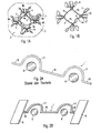
- Fig. 1A shows in a schematic, perspective view of an embodiment of a YIG bandpass filter 2, which has a base body 3 and in the embodiment, four formed in the base body 3 filter chambers 4 with as many YIG elements 6.
- the YIG elements 6 are spherically formed from an yttrium-iron garnet, mounted on holders 10, for example by gluing with epoxy resin and electromagnetically coupled by coupling lines 1.
- the filter chambers 4 are interconnected by slots 5, in which the coupling lines 1 are inserted.
- two of the filter chambers 4 are identical in the embodiment.
- the filter chambers 4 denoted by 4b have only the YIG elements 6.
- the number of filter chambers 4b is not limited to two, but may be one or more so that the total number of filter chambers 4 may be three or more.
- Fig. 1B shows for ease of understanding the arrangement of the coupling lines 1 and mounted on their holders 10 YIG elements 6 without the surrounding body.
- the coupling lines 1 are executed in the embodiment in two different forms.
- the filter chambers 4b interconnecting coupling line 1 is designed as input or output line 1a, while in the embodiment, three further coupling lines 1 are designed as connecting lines 1b.
- Fig. 1B shows, the coupling lines 1 on tabs 8, which serve on the one hand, the ground connection of the coupling lines 1 in the base body 3 and on the other hand, the fixation of the coupling lines 1 in the slots 5.
- the contact lugs 8 are rectangular in shape, wherein an edge length of the contact lugs 8 corresponds approximately to the axial thickness of the base body 2.
- FIGS. 2A and 2B is recognizable, whereby the coupling lines 1 according to Fig. 2B from conventional coupling lines 1 according to FIG Fig. 2A differ.
- the two embodiments have in common that in each case at least one curved portion 17 is provided, which surrounds a respective YIG element 6 so at least partially, that a center of the YIG element 6 coincides with a center of the curved portion 17. Furthermore, at least one line section 18 is provided.
- FIG. 2A shown coupling line 1 according to the prior art is bent from a wire.
- the YIG elements 6 in the in FIGS. 2A and 2B introduced basic body 3, not shown, and then inserted only roughly pre-bent wire in the slots 5.
- a measurement of the degree of coupling results where the coupling line 1 still needs to be bent. This is done manually by means of a suitable tool. Thereafter must be checked again and readjusted. For this purpose, each time the YIG filter 2 or YIG oscillator must be opened and then reassembled to make the measurement. The method is thus extremely complicated and often even leads to the fact that the workpiece must be completely discarded after several iterations, because no satisfactory coupling is achieved.
- the inventively designed coupling lines 1 according to Fig. 2B made of a metallic foil by suitable methods such as etching, eroding, cutting, in particular laser cutting or water jet cutting and / or punching and assembled. Thereafter, the correct positioning of the YIG elements 6 takes place relative to the coupling lines. 1
- the film is made of a copper-beryllium alloy to meet both the requirements of elasticity and strength.
- the thickness of the film is preferably about 50 microns.
- the preparation of the coupling lines 1 from the film takes place in several processing steps. First, the film is cleaned and applied on both sides with a positive resist at an alignment accuracy of about 5 microns in a layer thickness of about 5 microns to create a mask. Thereafter, the preparation of the coupling lines 1, for example, by spray etching with iron chloride. (FeCl 3) Subsequently, the liberated in the form of a carrier 9 with a predetermined number of coupling lines 1 of all paint residues and galvanically provided with a gold coating of about 5 microns. After that follows a curing process for example, one hour at 325 ° C. Then the coupling lines can be released from the film carrier 9 and installed.
- the coupling lines 1 have by the manufacturing method described a solid shape with a well-defined radius of curvature in the curved portions 17 at a uniform curvature.
- the YIG elements 6 are then aligned relative to the coupling lines 1. This is compared to the prior art simpler and associated with considerably less effort, because the manufacturing accuracy of the present invention designed coupling lines 1 is considerably larger than in manually curved coupling lines. 1
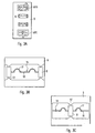
- Fig. 3A shows a schematic representation of a carrier 9, which contains the coupling lines 1 required for a YIG bandpass filter 2 with four YIG elements 6.
- the coupling lines 1 are formed in the embodiment in the form of an input or output line 1a and three connecting lines 1b.
- the former is in Fig. 3A arranged at the bottom of the film carrier 9, the latter above.
- Figs. 3B and 3C show the in Fig. 3A sections of support 9 labeled IIIB and IIIC Fig. 3B one of the three connecting lines 1b is shown while Fig. 3C the input or output line 1a shows.
- the coupling lines 1 are held by the process of etching, cutting, punching or eroding from the film prior to separation in the carrier 9 by webs 12 which are formed on the contact lugs 8.
- the coupling lines 1 are mounted in the base body 3 according to their shape and fixed in the base body 3 by soldering, welding or another method of maintaining the electrical conductivity.
Landscapes
- Control Of Motors That Do Not Use Commutators (AREA)
- Inductance-Capacitance Distribution Constants And Capacitance-Resistance Oscillators (AREA)
Abstract
Claims (6)
- Filtre YIG (2) ou oscillateur YIG, comportant une embase (3) dans lequel des chambres de filtre (4) sont réalisées, dans lequel chaque chambre de filtre (4) présente un élément YIG (6) et les chambres de filtre (4) sont reliées les unes aux autres par des rainures (5) dans l'embase (3), qui font saillie au-dessus des chambres de filtre, dans lequel une ligne de couplage (1) présente, en vue du couplage électromagnétique des éléments YIG (6), au moins un tronçon incurvé (17), qui comporte au moins partiellement un élément YIG (6), et au moins un tronçon de ligne (18) situé dans une rainure (5), dans lequel la ligne de couplage (1) est fixée au tronçon de ligne (18) de façon électriquement conductrice dans les rainures (5), caractérisé en ce que le tronçon de ligne (18) présente au moins une lamelle de contact (8) réalisé intégralement avec la ligne de couplage (1),
au moins une longueur de bord de la lamelle de contact (8) correspond environ à l'épaisseur axiale de l'embase (3) et la fixation de la ligne de couplage (1) est réalisée grâce à des lamelles de contact (8). - Filtre YIG (2) ou oscillateur YIG selon la revendication 1, caractérisé en ce que le au moins une lamelle de contact (8) est de forme rectangulaire.
- Filtre YIG (2) ou oscillateur YIG selon l'une des revendications 1 ou 2, caractérisé en ce que la ligne de couplage (1) est réalisée sous la forme d'une ligne d'entrée ou de sortie (1a) ou sous la forme d'une ligne de liaison (1b).
- Filtre YIG (2) ou oscillateur YIG selon la revendication 1, caractérisé en ce que la ligne de couplage (1) est une feuille métallique réalisée en un alliage de cuivre et de béryllium.
- Filtre YIG (2) ou oscillateur YIG selon la revendication 4, caractérisé en ce que l'épaisseur de la feuille est 10 à 100 µm, en particulier de préférence 25 à 75 µm, de préférence en particulier environ 50 µm.
- Filtre YIG (2) ou oscillateur YIG selon l'une des revendications 1 à 5, caractérisé en ce que le au moins un tronçon incurvé (17) de la ligne de couplage (1) présente un rayon de courbure.
Applications Claiming Priority (2)
| Application Number | Priority Date | Filing Date | Title |
|---|---|---|---|
| DE102004056259A DE102004056259A1 (de) | 2004-11-22 | 2004-11-22 | Kopplungsleitungen für einen YIG-Filter oder YIG-Oszillator und Verfahren zur Herstellung der Kopplungsleitungen |
| PCT/EP2005/011885 WO2006056314A1 (fr) | 2004-11-22 | 2005-11-07 | Lignes de couplage pour un filtre yig ou un oscillateur yig et procede pour produire ces lignes de couplage |
Publications (3)
| Publication Number | Publication Date |
|---|---|
| EP1815554A1 EP1815554A1 (fr) | 2007-08-08 |
| EP1815554B1 true EP1815554B1 (fr) | 2010-10-27 |
| EP1815554B8 EP1815554B8 (fr) | 2011-01-19 |
Family
ID=35735322
Family Applications (1)
| Application Number | Title | Priority Date | Filing Date |
|---|---|---|---|
| EP05813554A Expired - Lifetime EP1815554B8 (fr) | 2004-11-22 | 2005-11-07 | Lignes de couplage pour un filtre yig ou un oscillateur yig et procede pour produire ces lignes de couplage |
Country Status (5)
| Country | Link |
|---|---|
| US (2) | US7573357B2 (fr) |
| EP (1) | EP1815554B8 (fr) |
| JP (1) | JP4589402B2 (fr) |
| DE (2) | DE102004056259A1 (fr) |
| WO (1) | WO2006056314A1 (fr) |
Families Citing this family (3)
| Publication number | Priority date | Publication date | Assignee | Title |
|---|---|---|---|---|
| WO2020089255A1 (fr) * | 2018-10-29 | 2020-05-07 | Universität Hamburg | Résonateur magnétiquement accordable |
| TR201907601A2 (tr) * | 2019-05-20 | 2020-12-21 | Aselsan Elektronik Sanayi Ve Ticaret As | YIG Filtrelerinde Oluşan Merkez Frekans Kaymasını ve Doğrusallık Hatalarını Minimize Eden Yöntem |
| CN110165344B (zh) * | 2019-05-28 | 2021-08-27 | 西南应用磁学研究所 | 旋磁滤波器谐振电路结构 |
Citations (1)
| Publication number | Priority date | Publication date | Assignee | Title |
|---|---|---|---|---|
| FR2616972A1 (fr) * | 1987-06-22 | 1988-12-23 | Enertec | Filtre passe-bande a bille de grenat d'yttrium fer accordable en frequence et a large bande d'accord |
Family Cites Families (18)
| Publication number | Priority date | Publication date | Assignee | Title |
|---|---|---|---|---|
| NL165263B (nl) * | 1950-12-29 | Skf Ind Trading & Dev | Luchtgekoelde remschijf voor de schijfrem van een motorvoertuig. | |
| US3821668A (en) | 1973-03-12 | 1974-06-28 | Loral Corp | Electronically tunable microwave filter |
| JPS5850701U (ja) * | 1981-09-18 | 1983-04-06 | 株式会社アドバンテスト | マイクロ波バンドパスフイルタ |
| US4633205A (en) | 1985-11-25 | 1986-12-30 | Tektronix, Inc. | Loop coupled YIG resonator |
| US4857871A (en) | 1988-10-31 | 1989-08-15 | Harris David L | Magnetic field-tunable filter with plural section housing and method of making the same |
| JPH0429204U (fr) * | 1990-07-02 | 1992-03-09 | ||
| US5294899A (en) | 1992-07-29 | 1994-03-15 | Hewlett-Packard Company | YIG-tuned circuit with rotatable magnetic polepiece |
| EP0646962B1 (fr) * | 1993-04-14 | 2002-11-06 | Hitachi Construction Machinery Co., Ltd. | Procede d'usinage d'une feuille metallique, procede d'usinage d'une grille de connexion et procede d'usinage d'un dispositif a semi-conducteur |
| US5757125A (en) * | 1995-11-09 | 1998-05-26 | Astronics Corporation, Inc. | Electroluminescent lamp with lead attachment isolation structure, and rotary abrasion method of manufacture thereof |
| US5959513A (en) * | 1997-05-13 | 1999-09-28 | Verticom, Inc. | Microwave ferrite resonator mounting structure having reduced mechanical vibration sensitivity |
| JP3622639B2 (ja) | 2000-05-30 | 2005-02-23 | 株式会社村田製作所 | 非可逆回路素子の製造方法 |
| US6670208B2 (en) * | 2000-06-23 | 2003-12-30 | Nec Corporation | Optical circuit in which fabrication is easy |
| GB2365007B (en) * | 2000-07-21 | 2002-06-26 | Murata Manufacturing Co | Insulative ceramic compact |
| US6772515B2 (en) * | 2000-09-27 | 2004-08-10 | Hitachi, Ltd. | Method of producing multilayer printed wiring board |
| US6727775B2 (en) * | 2001-11-29 | 2004-04-27 | Sirenza Microdevices, Inc. | Ferrite crystal resonator coupling structure |
| DE10212018A1 (de) * | 2002-03-19 | 2003-10-02 | Bosch Gmbh Robert | Isolationsmaterial und Gassensor |
| US7198764B2 (en) * | 2003-03-05 | 2007-04-03 | Delphi Technologies, Inc. | Gas treatment system and a method for using the same |
| US20060035782A1 (en) * | 2004-08-12 | 2006-02-16 | Ford Global Technologies, Llc | PROCESSING METHODS AND FORMULATIONS TO ENHANCE STABILITY OF LEAN-NOx-TRAP CATALYSTS BASED ON ALKALI- AND ALKALINE-EARTH-METAL COMPOUNDS |
-
2004
- 2004-11-22 DE DE102004056259A patent/DE102004056259A1/de not_active Withdrawn
-
2005
- 2005-11-07 WO PCT/EP2005/011885 patent/WO2006056314A1/fr not_active Ceased
- 2005-11-07 DE DE502005010453T patent/DE502005010453D1/de not_active Expired - Lifetime
- 2005-11-07 US US11/667,897 patent/US7573357B2/en not_active Expired - Lifetime
- 2005-11-07 JP JP2007541743A patent/JP4589402B2/ja not_active Expired - Lifetime
- 2005-11-07 EP EP05813554A patent/EP1815554B8/fr not_active Expired - Lifetime
-
2009
- 2009-02-11 US US12/369,498 patent/US8327520B2/en active Active
Patent Citations (1)
| Publication number | Priority date | Publication date | Assignee | Title |
|---|---|---|---|---|
| FR2616972A1 (fr) * | 1987-06-22 | 1988-12-23 | Enertec | Filtre passe-bande a bille de grenat d'yttrium fer accordable en frequence et a large bande d'accord |
Also Published As
| Publication number | Publication date |
|---|---|
| EP1815554B8 (fr) | 2011-01-19 |
| DE102004056259A1 (de) | 2006-05-24 |
| WO2006056314A1 (fr) | 2006-06-01 |
| US20090144964A1 (en) | 2009-06-11 |
| US7573357B2 (en) | 2009-08-11 |
| JP2008521299A (ja) | 2008-06-19 |
| EP1815554A1 (fr) | 2007-08-08 |
| JP4589402B2 (ja) | 2010-12-01 |
| US20080211605A1 (en) | 2008-09-04 |
| DE502005010453D1 (de) | 2010-12-09 |
| US8327520B2 (en) | 2012-12-11 |
Similar Documents
| Publication | Publication Date | Title |
|---|---|---|
| DE10207342A1 (de) | Verfahren zum Liefern unterschiedlicher Frequenzeinstellungen bei einem akustischen Dünnfilmvolumenresonator- (FBAR-) Filter und Vorrichtung, die das Verfahren beinhaltet | |
| DE10207341A1 (de) | Verfahren zum Erzeugen akustischer Dünnfilmvolumenresonatoren (FBARs) mit unterschiedlichen Frequenzen auf einem einzelnen Substrat und Vorrichtung, die das Verfahren beinhaltet | |
| EP3593412B1 (fr) | Élément de conducteur intérieur et procédé de production d'un système | |
| WO2013083257A1 (fr) | Procédé de réalisation d'un connecteur enfichable | |
| EP1128476B2 (fr) | Procédé de fabrication d'un connecteur | |
| EP1815554B1 (fr) | Lignes de couplage pour un filtre yig ou un oscillateur yig et procede pour produire ces lignes de couplage | |
| DE4310369A1 (de) | Adapter | |
| WO2005053103A1 (fr) | Cable coaxial et son procede de production | |
| EP1741162B1 (fr) | Unite fonctionnelle electrique et procede pour sa production | |
| EP0811995B1 (fr) | Enroulement magnétique et procédé de sa fabrication | |
| DE69614983T2 (de) | Piezoelektrischer Resonator | |
| EP1318565B1 (fr) | Antenne, en particuliere antenne de radiotelephonie mobile, avec moyen de centrage pendant la fabrication | |
| EP1771915B1 (fr) | Corps de base pour un filtre yig ou un oscillateur yig | |
| DE3408581A1 (de) | Resonator | |
| EP1774543B1 (fr) | Composant électrique et procédé pour produire un composant électrique | |
| EP3465841B1 (fr) | Connecteur coaxial enfichable | |
| DE10045073A1 (de) | Steckerelement und zugehöriges Herstellungsverfahren | |
| DE3200117C2 (de) | Einbau-Bandpaßfilteranordnung für ein Koaxialkabel | |
| DE4130390C2 (de) | Widerstandselement | |
| EP0957529A1 (fr) | Procédé pour accorder la fréquence de résonance d' un résonateur en anneau | |
| DE19526583A1 (de) | Dielektrisches Filter | |
| DE2905677A1 (de) | Hohlraum-resonator | |
| EP3133696A1 (fr) | Dispositif de mise en contact et procede de fabrication | |
| DE102024127800B3 (de) | Verfahren zum zumindest teil- oder bereichsweisen elektrischen isolieren einer erdungs- und/oder kurzschließvorrichtung | |
| DE3510369C2 (fr) |
Legal Events
| Date | Code | Title | Description |
|---|---|---|---|
| PUAI | Public reference made under article 153(3) epc to a published international application that has entered the european phase |
Free format text: ORIGINAL CODE: 0009012 |
|
| 17P | Request for examination filed |
Effective date: 20070404 |
|
| AK | Designated contracting states |
Kind code of ref document: A1 Designated state(s): DE FR GB |
|
| DAX | Request for extension of the european patent (deleted) | ||
| 17Q | First examination report despatched |
Effective date: 20070914 |
|
| RBV | Designated contracting states (corrected) |
Designated state(s): DE FR GB |
|
| GRAP | Despatch of communication of intention to grant a patent |
Free format text: ORIGINAL CODE: EPIDOSNIGR1 |
|
| GRAS | Grant fee paid |
Free format text: ORIGINAL CODE: EPIDOSNIGR3 |
|
| GRAA | (expected) grant |
Free format text: ORIGINAL CODE: 0009210 |
|
| AK | Designated contracting states |
Kind code of ref document: B1 Designated state(s): DE FR GB |
|
| REG | Reference to a national code |
Ref country code: GB Ref legal event code: FG4D Free format text: NOT ENGLISH |
|
| REF | Corresponds to: |
Ref document number: 502005010453 Country of ref document: DE Date of ref document: 20101209 Kind code of ref document: P |
|
| PLBE | No opposition filed within time limit |
Free format text: ORIGINAL CODE: 0009261 |
|
| STAA | Information on the status of an ep patent application or granted ep patent |
Free format text: STATUS: NO OPPOSITION FILED WITHIN TIME LIMIT |
|
| 26N | No opposition filed |
Effective date: 20110728 |
|
| REG | Reference to a national code |
Ref country code: DE Ref legal event code: R097 Ref document number: 502005010453 Country of ref document: DE Effective date: 20110728 |
|
| REG | Reference to a national code |
Ref country code: FR Ref legal event code: PLFP Year of fee payment: 11 |
|
| REG | Reference to a national code |
Ref country code: FR Ref legal event code: PLFP Year of fee payment: 12 |
|
| REG | Reference to a national code |
Ref country code: FR Ref legal event code: PLFP Year of fee payment: 13 |
|
| P01 | Opt-out of the competence of the unified patent court (upc) registered |
Effective date: 20230525 |
|
| PGFP | Annual fee paid to national office [announced via postgrant information from national office to epo] |
Ref country code: DE Payment date: 20241119 Year of fee payment: 20 |
|
| PGFP | Annual fee paid to national office [announced via postgrant information from national office to epo] |
Ref country code: GB Payment date: 20241121 Year of fee payment: 20 |
|
| PGFP | Annual fee paid to national office [announced via postgrant information from national office to epo] |
Ref country code: FR Payment date: 20241120 Year of fee payment: 20 |
|
| REG | Reference to a national code |
Ref country code: DE Ref legal event code: R071 Ref document number: 502005010453 Country of ref document: DE |
|
| REG | Reference to a national code |
Ref country code: GB Ref legal event code: PE20 Expiry date: 20251106 |