EP1815562B1 - Elektrisches verbindungselement zum verbinden von versorgungsleitungen insbesondere in einem flugzeug - Google Patents
Elektrisches verbindungselement zum verbinden von versorgungsleitungen insbesondere in einem flugzeug Download PDFInfo
- Publication number
- EP1815562B1 EP1815562B1 EP05815165A EP05815165A EP1815562B1 EP 1815562 B1 EP1815562 B1 EP 1815562B1 EP 05815165 A EP05815165 A EP 05815165A EP 05815165 A EP05815165 A EP 05815165A EP 1815562 B1 EP1815562 B1 EP 1815562B1
- Authority
- EP
- European Patent Office
- Prior art keywords
- connector
- connection element
- connector socket
- socket
- electrical connection
- Prior art date
- Legal status (The legal status is an assumption and is not a legal conclusion. Google has not performed a legal analysis and makes no representation as to the accuracy of the status listed.)
- Expired - Lifetime
Links
Images


Classifications
-
- H—ELECTRICITY
- H01—ELECTRIC ELEMENTS
- H01R—ELECTRICALLY-CONDUCTIVE CONNECTIONS; STRUCTURAL ASSOCIATIONS OF A PLURALITY OF MUTUALLY-INSULATED ELECTRICAL CONNECTING ELEMENTS; COUPLING DEVICES; CURRENT COLLECTORS
- H01R13/00—Details of coupling devices of the kinds covered by groups H01R12/70 or H01R24/00 - H01R33/00
- H01R13/66—Structural association with built-in electrical component
- H01R13/70—Structural association with built-in electrical component with built-in switch
- H01R13/71—Contact members of coupling parts operating as switch, e.g. linear or rotational movement required after mechanical engagement of coupling part to establish electrical connection
Definitions
- the invention relates to an electrical connection element for connecting supply lines, in particular in an aircraft.
- Such a threaded connection element is known from DE 94 12 215 U .
- the FR 696 321 A discloses a method and a device for joining wires.
- the wires have a section shaped as a spiral of Archimedes.
- a sleeve has an internal section corresponding to the external shape of the wires. The ends of the wires are inserted into the sleeve and a non-positive connection is established by rotation of the sleeve relative to the wires.
- connection element There may be a need to provide a simple electrical connection element which makes possible quick and secure connecting and disconnecting of the connection element.
- a connection element for connecting supply lines comprises a connector socket and a connector that is insertable into the connector socket, wherein the connector is axially rotatable in the connector socket, as a result of which a non-positive connection between the connector and the connector socket is established.
- a secure non-positive connection may be established in a simple manner.
- the connector may be simply inserted into the connector socket and axially rotated, which may reduce the installation effort.
- the same may apply analogously for the disconnecting of the connection. Doing without a threaded pin may make it possible to reduce the expenditure and if need be to save weight. If need be it may be possible to do without a carrier for several connection elements.
- Supply lines are lines to supply, in particular, aircraft components with electrical energy.
- the connection element according to the invention is therefore delimited in relation to electrical connectors for signal lines or control lines.
- Connecting supply lines also includes the branching off of supply lines.
- the invention includes the connection of any desired number of supply lines with any number of additional supply lines.
- the contact surfaces between the connector and the connector socket may be preferably electrically conductive, in particular metallic.
- the connector and the connector socket comprise corresponding radially tapered contact surfaces.
- This may make it possible to provide the largest possible contact surfaces, and thus may secure contact, merely by axial rotation of the connector in the connector socket.
- the number of the radially tapered contact surfaces of the connector and the connector socket respectively may be at least three so as to ensure an even mechanical load on the connector and the connector socket respectively.
- a large contact surface may be achieved by a small number of contact surfaces.
- the number of radially tapered contact surfaces of the connector and the connector socket respectively may be thus preferably at most five.
- connection element for connecting supply lines in aircraft may comprise, in particular, the connection element is essentially formed in one part and comprises two clamping receptacles for the ends of the supply lines to be connected.
- the term "essentially” means "apart from parts that are insignificant in the context of the invention” and thus relates to the clamping receptacles and if necessary to a conductive adapter.
- the supply lines may be simply inserted into the clamping receptacles and may be clamped into place. Doing without a threaded pin may make it possible to reduce the effort and to save weight. If need be, it may be possible to do without a carrier for several connection elements.
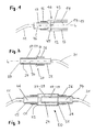
- An electrical connection element 50 comprises a connector socket 10 and a connector 20.
- the connector socket 10 is connected to an electrical supply line 11 and comprises a cylindrical metallic receptacle 14 that is connected to the supply line 11 by way of a metallic bottom part 45 and a metallic adapter 46.
- the connector socket 10 comprises a housing 12 with a housing part 13 for the receptacle 14, and with a housing part 15 for the adaptor 46.
- An operating element 16 is attached to the housing part 15.
- the connector 20 comprises a metallic contact pin 24, which by way of a metallic adaptor 34 is conductively connected to the supply line 21, as well as a housing part 25 with an operating element 26.
- the contact pin 24 comprises outer metallic contact surfaces 27-29.
- the contact surfaces 27-29 of the contact pin 24 taper radially clockwise, as shown in Figs 4, 5 : starting from the largest radial extension r1 the radius of the contact surface 29 (see Fig. 5 ) continuously diminishes clockwise until the minimum radial extension r2 is reached.
- the receptacle 14 of the connector socket 10 comprises inner metallic contact surfaces 17-19 that correspond to the outer contact surfaces 27-29 of the connector 20 and therefore also taper off radially in clockwise direction. In each case the transition from the minimum to the maximum radial extension of the contact surfaces 17, 18, 19 is formed by an essentially radially extending limit stop 40, 41, 42.
- the contact pin 24 of the connector 20 is inserted into the receptacle 14 of the connector socket 10.
- the contact pin 24 is expediently oriented such that the limit stops 40-42 of the connector socket 10 form guides for the limit stops 30-32 of the contact pin 24.
- the limit stops 40-42 of the connector socket 10 are in contact with the limit stops 30-32 of the connector 20, the external radius of the contact pin 24 is somewhat smaller than the internal radius of the receptacle 14 of the connector socket 10 so that in total a clearance of a few mm, for example ranging from 0.5 to 2 mm, results. This makes possible non-problematic insertion of the contact pin 24 into the receptacle 14 of the connector socket 10.
- the face 33 of the contact pin 24 can rest against the bottom 43 of the receptacle 14 of the connector socket.
- the connector socket 10 and the connector 20 are axially rotated clockwise against each other, i.e. on the longitudinal axis L of the connector 20 and the connector socket 10 respectively. This can for example take place by using tools applied to the operating elements 16, 26. Manual rotation is also possible. Rotation takes place until, due to their radial taper, the contact surfaces 27-29 of the contact pin 24 establish a non-positive and/or frictionally engaged connection with the contact surfaces 17-19 of the receptacle 14 of the connector socket 10.
- the closing angle i.e. the angle between the limit stop and firm seating, as shown in Fig.
- connection element 50 is for example 20° to 30°.
- a catch device can be provided so that the connector 20 in the closed position (see Fig. 5 ) clicks into the connector socket 10.
- a locking device can be provided so as to lock the connector 20 in the closed position in the connector socket 10.
- the number of contact surfaces 17-19 and contact surfaces 27-29 respectively is at least three so as to ensure even loading of the connector 20 and of the connector socket 10 respectively.
- four or more contact surfaces for each connector 20 and each connector socket 10 respectively at the same closing angle would reduce the contact surface overall.
- the number of radially tapering-off contact surfaces of the connector and of the connector socket respectively is thus preferably at most five, preferably precisely three.
- the contact surfaces 17-19 and 27-29 respectively are preferably arranged at even angular spacing, for example at 120° in the case of three contact surfaces (see Figs 4, 5 ).
- the connector 20 and the connector socket 10 form a disconnectable connection element 50.
- the connector 20 is disconnected and rotated in the connector socket 10 in anticlockwise rotation, for example by using tools applied to the operating elements 16, 26, until the limit stops 30-32 come to rest against the limit stops 40-42 of the connector socket 10.
- the contact pin 24 can be pulled with some play from the receptacle 14 of the connector socket 10, wherein the limit stops 40-42 of the connector socket form guides for the limit stops 30-32 of the contact pin 24.
- a seal or sealing means 51 for corrosion protection can be provided between the connector 20 and the connector socket 10 .
- the housing 13, 15 of the connector socket 10 and the housing 25 of the connector 20 are insulating. Due to any complete insulation of the connection element 50 in the closed state no further measures to avoid short circuits and measures for corrosion protection are required.
- insulation 52 for the entire connection element 50 can be provided, for example in the form of a shrinkdown sleeve.
- a socket unit 60 having a plurality of connector receptacles 14 each adapted to receive one connector 20. All connector receptacles 14 are connected to a supply line 61 by way of a common electrically conductive carrier structure 62. Insulated positions 63-65 are provided for the carrier structure. In this way a distributor can be implemented i.e. connecting of a plurality of supply lines to a supply line wherein each of the plurality of supply lines is connected to a connector.
- connection element 70 which comprises two clamping receptacles 71, 72 for the ends of two supply lines 73, 74 to be connected, which supply lines 73, 74 comprise insulation 75.
- the clamping receptacles 71, 72 are conductively connected in a single piece by means of a metallic adaptor 76.
- the connection element 70 is therefore preferably used for one-time connection of supply lines that need not be undone during the service life of the aircraft.
- Comprehensive insulation 77 for the connection element 70 for example in the form of a shrinkdown sleeve, can be provided.
Landscapes
- Connector Housings Or Holding Contact Members (AREA)
- Details Of Connecting Devices For Male And Female Coupling (AREA)
Claims (8)
- Ein elektrisches Verbindungselement (50) zum Verbinden von Versorgungsleitungen (11,21), insbesondere in einem Flugzeug, wobei das Verbindungselement (50) aufweist:eine Verbindungsbuchse (10),und einen Verbinder (20),wobei der Verbinder (20) und die Verbindungsbuchse (10) entsprechende sich radial verjüngende Kontaktflächen (17, 18, 19, 27, 28, 29) aufweisen,wobei der Verbinder (20) in die Verbindungsbuchse (10) einführbar ist; undwobei der Verbinder (20) um eine Achse in der Verbindungsbuchse (10) drehbar ist, was zur Folge hat, dass sich eine kraftschlüssige Verbindung zwischen dem Verbinder (20) und der Verbindungsbuchse (10) einstellt,wobei die Anzahl der sich radial verjüngenden Kontaktflächen (17, 18, 19, 27, 28, 29) des Verbinders (20) und der Verbindungsbuchse (10) jeweils zumindest drei ist.
- Das elektrisches Verbindungselement (50) nach Anspruch 1,
wobei ein elektrischer Kontakt durch eine kraftschlüssige Verbindung zwischen dem Verbinder (20) und der Verbindungsbuchse (10) hergestellt wird. - Das elektrisches Verbindungselement (50) nach einem der Ansprüche 1 bis 2,
wobei der Verbinder (20) in die Verbindungsbuchse (10) mit radialem Spiel einführbar ist. - Das elektrisches Verbindungselement (50) nach einem der Ansprüche 1 bis 3,
wobei der Verbinder (20) und die Verbindungsbuchse (10) entsprechende sich radial erstreckende Anschläge (30, 31, 32, 40, 41, 42) aufweisen. - Das elektrisches Verbindungselement (50) nach einem der Ansprüche 1 bis 4,
wobei der Verbinder (20) und die Verbindungsbuchse (10) Elemente (16, 26) zum Anwenden von Werkzeug aufweisen. - Das elektrisches Verbindungselement (50) nach einem der Ansprüche 1 bis 5,
wobei eine Dichtung (51) zwischen dem Verbinder (20) und der Verbindungsbuchse (10) vorgesehen ist. - Das elektrisches Verbindungselement (50) nach einem der Ansprüche 1 bis 6,
wobei der Verbinder (20) und die Verbindungsbuchse (10) ein isolierendes Gehäuse (12, 25) aufweisen. - Das elektrisches Verbindungselement (50) nach einem der Ansprüche 1 bis 6,
wobei eine Fang- und/oder Arretierungs-Vorrichtung zum Fangen und/oder Arretieren des Verbinders (20) in der Verbindungsbuchse (10) in der geschlossenen Position vorgesehen ist.
Applications Claiming Priority (2)
| Application Number | Priority Date | Filing Date | Title |
|---|---|---|---|
| DE102004056648A DE102004056648A1 (de) | 2004-11-24 | 2004-11-24 | Elektrisches Verbindungselement zum Verbinden von Versorgungsleitungen insbesondere in einem Flugzeug |
| PCT/EP2005/012581 WO2006056446A1 (en) | 2004-11-24 | 2005-11-24 | Electrical connection element for connecting supply lines, in particular in an aircraft |
Publications (3)
| Publication Number | Publication Date |
|---|---|
| EP1815562A1 EP1815562A1 (de) | 2007-08-08 |
| EP1815562B1 true EP1815562B1 (de) | 2010-01-06 |
| EP1815562B8 EP1815562B8 (de) | 2010-03-10 |
Family
ID=35744927
Family Applications (1)
| Application Number | Title | Priority Date | Filing Date |
|---|---|---|---|
| EP05815165A Expired - Lifetime EP1815562B8 (de) | 2004-11-24 | 2005-11-24 | Elektrisches verbindungselement zum verbinden von versorgungsleitungen insbesondere in einem flugzeug |
Country Status (5)
| Country | Link |
|---|---|
| US (1) | US7547222B2 (de) |
| EP (1) | EP1815562B8 (de) |
| CN (1) | CN100588045C (de) |
| DE (2) | DE102004056648A1 (de) |
| WO (1) | WO2006056446A1 (de) |
Families Citing this family (5)
| Publication number | Priority date | Publication date | Assignee | Title |
|---|---|---|---|---|
| CN102412490B (zh) * | 2011-12-29 | 2014-01-29 | 苏州升德精密电气有限公司 | 一种二段旋转式插座 |
| CN104051908B (zh) * | 2014-06-30 | 2017-08-08 | 张行钢 | 旋转式棘齿自锁机构 |
| EP3410543B1 (de) | 2017-05-31 | 2023-04-19 | ITT Manufacturing Enterprises LLC | Spleissverbinderanordnungen |
| ES2929715T3 (es) * | 2017-10-23 | 2022-12-01 | Hypertac S P A | Sistema de conexión eléctrica |
| CN110265831A (zh) * | 2019-06-17 | 2019-09-20 | 王新武 | 一种电气传动控制系统接入设备 |
Family Cites Families (11)
| Publication number | Priority date | Publication date | Assignee | Title |
|---|---|---|---|---|
| FR696321A (fr) | 1929-06-01 | 1930-12-29 | Fr De Filetage Indesserrable D | Procédé et dispositif de jonction de fils, tels que des conducteurs électriques |
| DE1839468U (de) * | 1961-08-29 | 1961-10-19 | Pfisterer Elektrotech Karl | Pressverbinder mit federnden innenhuelsen. |
| FR2307169A1 (fr) | 1975-04-09 | 1976-11-05 | Izaguirre Michel | Systeme de fixation largable a baionnette |
| DE8019782U1 (de) | 1980-07-23 | 1980-12-04 | May & Christe Gmbh, Transformatorenwerke, 6370 Oberursel | Elektrisches Verbindungsstück |
| US4834678A (en) * | 1988-05-31 | 1989-05-30 | Amp Incorporated | High voltage contact assembly |
| DE4102318A1 (de) * | 1991-01-26 | 1992-08-06 | Airbus Gmbh | Verteiler fuer elektrische anlagen |
| DE9412215U1 (de) * | 1994-07-28 | 1994-09-22 | Lamson + Sessions GmbH, 58840 Plettenberg | Kabelschuh mit Befestigungselement |
| US6152608A (en) * | 1998-04-10 | 2000-11-28 | Packard Hughes Interconnect Company | Snap lock connector for optical fiber systems |
| US6077132A (en) * | 1998-10-26 | 2000-06-20 | Wpi/Viking | Electrical connector with replaceable pin contacts not requiring accompanying re-termination |
| US6641421B1 (en) * | 2002-09-09 | 2003-11-04 | Reynolds Industries, Inc. | High-voltage electrical connector and related method |
| US7097486B2 (en) * | 2005-02-03 | 2006-08-29 | Cushcraft Corporation | Low-cost weatherproof cable feedthrough |
-
2004
- 2004-11-24 DE DE102004056648A patent/DE102004056648A1/de not_active Ceased
-
2005
- 2005-11-24 US US11/667,431 patent/US7547222B2/en not_active Expired - Fee Related
- 2005-11-24 WO PCT/EP2005/012581 patent/WO2006056446A1/en not_active Ceased
- 2005-11-24 DE DE602005018814T patent/DE602005018814D1/de not_active Expired - Lifetime
- 2005-11-24 EP EP05815165A patent/EP1815562B8/de not_active Expired - Lifetime
- 2005-11-24 CN CN200580039994A patent/CN100588045C/zh not_active Expired - Fee Related
Also Published As
| Publication number | Publication date |
|---|---|
| EP1815562B8 (de) | 2010-03-10 |
| CN101061608A (zh) | 2007-10-24 |
| DE102004056648A1 (de) | 2006-06-01 |
| EP1815562A1 (de) | 2007-08-08 |
| US20080102678A1 (en) | 2008-05-01 |
| US7547222B2 (en) | 2009-06-16 |
| DE602005018814D1 (de) | 2010-02-25 |
| WO2006056446A1 (en) | 2006-06-01 |
| CN100588045C (zh) | 2010-02-03 |
Similar Documents
| Publication | Publication Date | Title |
|---|---|---|
| ES2671240T3 (es) | Conector eléctrico con mecanismo de puesta a tierra | |
| US4874327A (en) | Universal cable head for a multiconductor logging cable | |
| US8834195B2 (en) | Cable connector system | |
| EP2854240B1 (de) | Permanente geschliffenen Spitze zum Spleißen von Verbindern | |
| US11271342B2 (en) | Pin and sleeve devices | |
| EP1815562B1 (de) | Elektrisches verbindungselement zum verbinden von versorgungsleitungen insbesondere in einem flugzeug | |
| US12212092B2 (en) | Power cable connectors and assemblies | |
| US11515665B2 (en) | Pin and sleeve device with features to facilitate easier assembly | |
| EP2685563B1 (de) | Haltevorrichtung und Verriegelung für elektrischen Steckverbinder | |
| US12347966B2 (en) | Deadbreak connector | |
| EP3172743B1 (de) | Elektrische verbindungskomponente | |
| CN105270598B (zh) | 用于飞行器中的电位均衡的金属主结构元件 | |
| US20240047899A1 (en) | High-current plug connector for a battery management system | |
| AU2016102478A4 (en) | Electrical plug and assembly | |
| AU2003203525B2 (en) | A Plug for a Mine Cable | |
| GB2361364A (en) | Connector having wires folded back and held in place by a ring | |
| HK1223456B (en) | Electrical connector assembly comprising a grounding link and corresponding method of connection |
Legal Events
| Date | Code | Title | Description |
|---|---|---|---|
| PUAI | Public reference made under article 153(3) epc to a published international application that has entered the european phase |
Free format text: ORIGINAL CODE: 0009012 |
|
| 17P | Request for examination filed |
Effective date: 20070516 |
|
| AK | Designated contracting states |
Kind code of ref document: A1 Designated state(s): DE FR GB IT SE |
|
| 17Q | First examination report despatched |
Effective date: 20071113 |
|
| DAX | Request for extension of the european patent (deleted) | ||
| RBV | Designated contracting states (corrected) |
Designated state(s): DE FR GB IT SE |
|
| GRAP | Despatch of communication of intention to grant a patent |
Free format text: ORIGINAL CODE: EPIDOSNIGR1 |
|
| GRAS | Grant fee paid |
Free format text: ORIGINAL CODE: EPIDOSNIGR3 |
|
| GRAA | (expected) grant |
Free format text: ORIGINAL CODE: 0009210 |
|
| AK | Designated contracting states |
Kind code of ref document: B1 Designated state(s): DE FR GB IT SE |
|
| REG | Reference to a national code |
Ref country code: GB Ref legal event code: FG4D |
|
| RAP2 | Party data changed (patent owner data changed or rights of a patent transferred) |
Owner name: AIRBUS OPERATIONS GMBH |
|
| REF | Corresponds to: |
Ref document number: 602005018814 Country of ref document: DE Date of ref document: 20100225 Kind code of ref document: P |
|
| PG25 | Lapsed in a contracting state [announced via postgrant information from national office to epo] |
Ref country code: SE Free format text: LAPSE BECAUSE OF FAILURE TO SUBMIT A TRANSLATION OF THE DESCRIPTION OR TO PAY THE FEE WITHIN THE PRESCRIBED TIME-LIMIT Effective date: 20100106 |
|
| PLBE | No opposition filed within time limit |
Free format text: ORIGINAL CODE: 0009261 |
|
| STAA | Information on the status of an ep patent application or granted ep patent |
Free format text: STATUS: NO OPPOSITION FILED WITHIN TIME LIMIT |
|
| 26N | No opposition filed |
Effective date: 20101007 |
|
| PG25 | Lapsed in a contracting state [announced via postgrant information from national office to epo] |
Ref country code: IT Free format text: LAPSE BECAUSE OF FAILURE TO SUBMIT A TRANSLATION OF THE DESCRIPTION OR TO PAY THE FEE WITHIN THE PRESCRIBED TIME-LIMIT Effective date: 20100106 |
|
| REG | Reference to a national code |
Ref country code: FR Ref legal event code: PLFP Year of fee payment: 11 |
|
| REG | Reference to a national code |
Ref country code: DE Ref legal event code: R082 Ref document number: 602005018814 Country of ref document: DE Representative=s name: LKGLOBAL | LORENZ & KOPF PARTG MBB PATENTANWAE, DE Ref country code: DE Ref legal event code: R082 Ref document number: 602005018814 Country of ref document: DE Representative=s name: KOPF WESTENBERGER WACHENHAUSEN PATENTANWAELTE , DE |
|
| REG | Reference to a national code |
Ref country code: FR Ref legal event code: PLFP Year of fee payment: 12 |
|
| REG | Reference to a national code |
Ref country code: FR Ref legal event code: PLFP Year of fee payment: 13 |
|
| PGFP | Annual fee paid to national office [announced via postgrant information from national office to epo] |
Ref country code: DE Payment date: 20191121 Year of fee payment: 15 |
|
| PGFP | Annual fee paid to national office [announced via postgrant information from national office to epo] |
Ref country code: FR Payment date: 20191120 Year of fee payment: 15 |
|
| PGFP | Annual fee paid to national office [announced via postgrant information from national office to epo] |
Ref country code: GB Payment date: 20191120 Year of fee payment: 15 |
|
| REG | Reference to a national code |
Ref country code: DE Ref legal event code: R119 Ref document number: 602005018814 Country of ref document: DE |
|
| GBPC | Gb: european patent ceased through non-payment of renewal fee |
Effective date: 20201124 |
|
| PG25 | Lapsed in a contracting state [announced via postgrant information from national office to epo] |
Ref country code: FR Free format text: LAPSE BECAUSE OF NON-PAYMENT OF DUE FEES Effective date: 20201130 |
|
| PG25 | Lapsed in a contracting state [announced via postgrant information from national office to epo] |
Ref country code: GB Free format text: LAPSE BECAUSE OF NON-PAYMENT OF DUE FEES Effective date: 20201124 Ref country code: DE Free format text: LAPSE BECAUSE OF NON-PAYMENT OF DUE FEES Effective date: 20210601 |