EP1815892B1 - Schlägergriff mit ergonomischer Schlägereigenschaft, entsprechendes Griffsortiment und Schlägersortiment - Google Patents
Schlägergriff mit ergonomischer Schlägereigenschaft, entsprechendes Griffsortiment und Schlägersortiment Download PDFInfo
- Publication number
- EP1815892B1 EP1815892B1 EP07356014A EP07356014A EP1815892B1 EP 1815892 B1 EP1815892 B1 EP 1815892B1 EP 07356014 A EP07356014 A EP 07356014A EP 07356014 A EP07356014 A EP 07356014A EP 1815892 B1 EP1815892 B1 EP 1815892B1
- Authority
- EP
- European Patent Office
- Prior art keywords
- shaft
- bulge
- equal
- region
- notably
- Prior art date
- Legal status (The legal status is an assumption and is not a legal conclusion. Google has not performed a legal analysis and makes no representation as to the accuracy of the status listed.)
- Not-in-force
Links
Images

Classifications
-
- A—HUMAN NECESSITIES
- A63—SPORTS; GAMES; AMUSEMENTS
- A63B—APPARATUS FOR PHYSICAL TRAINING, GYMNASTICS, SWIMMING, CLIMBING, OR FENCING; BALL GAMES; TRAINING EQUIPMENT
- A63B60/00—Details or accessories of golf clubs, bats, rackets or the like
- A63B60/06—Handles
- A63B60/12—Handles contoured according to the anatomy of the user's hand
-
- A—HUMAN NECESSITIES
- A63—SPORTS; GAMES; AMUSEMENTS
- A63B—APPARATUS FOR PHYSICAL TRAINING, GYMNASTICS, SWIMMING, CLIMBING, OR FENCING; BALL GAMES; TRAINING EQUIPMENT
- A63B49/00—Stringed rackets, e.g. for tennis
- A63B49/02—Frames
- A63B49/08—Frames with special construction of the handle
-
- A—HUMAN NECESSITIES
- A63—SPORTS; GAMES; AMUSEMENTS
- A63B—APPARATUS FOR PHYSICAL TRAINING, GYMNASTICS, SWIMMING, CLIMBING, OR FENCING; BALL GAMES; TRAINING EQUIPMENT
- A63B60/00—Details or accessories of golf clubs, bats, rackets or the like
- A63B60/06—Handles
- A63B60/10—Handles with means for indicating correct holding positions
-
- A—HUMAN NECESSITIES
- A63—SPORTS; GAMES; AMUSEMENTS
- A63B—APPARATUS FOR PHYSICAL TRAINING, GYMNASTICS, SWIMMING, CLIMBING, OR FENCING; BALL GAMES; TRAINING EQUIPMENT
- A63B2102/00—Application of clubs, bats, rackets or the like to the sporting activity ; particular sports involving the use of balls and clubs, bats, rackets, or the like
- A63B2102/02—Tennis
-
- A—HUMAN NECESSITIES
- A63—SPORTS; GAMES; AMUSEMENTS
- A63B—APPARATUS FOR PHYSICAL TRAINING, GYMNASTICS, SWIMMING, CLIMBING, OR FENCING; BALL GAMES; TRAINING EQUIPMENT
- A63B2102/00—Application of clubs, bats, rackets or the like to the sporting activity ; particular sports involving the use of balls and clubs, bats, rackets, or the like
- A63B2102/04—Badminton
-
- A—HUMAN NECESSITIES
- A63—SPORTS; GAMES; AMUSEMENTS
- A63B—APPARATUS FOR PHYSICAL TRAINING, GYMNASTICS, SWIMMING, CLIMBING, OR FENCING; BALL GAMES; TRAINING EQUIPMENT
- A63B2102/00—Application of clubs, bats, rackets or the like to the sporting activity ; particular sports involving the use of balls and clubs, bats, rackets, or the like
- A63B2102/06—Squash
Definitions
- the present invention relates to a racket handle, a racket comprising such a handle, and a range of handles comprising the aforementioned handle, and a range of rackets comprising the aforementioned racket.
- the handle of the invention is likely to be used in any type of racket sport, including tennis, badminton or squash.
- racket comprises, in addition to the aforementioned handle, a frame that defines either a sieve in the case of badminton, tennis or squash, or a solid striking surface.
- a racket handle comprises a polygonal section, most often octagonal, whose transverse dimensions are constant along this handle. This therefore implies a disadvantage, since the shape of this handle is not ergonomic, since it does not correspond to the curvature of the palm of the hand.
- EP-B-0 291 576 describes a handle for racket which has, in the region of the hand, a rounded and without edge, which presents a bulge of larger transverse dimension. At both ends, this edgeless area is transformed into polygonal section touch zones.
- Such a handle however involves a disadvantage, related in particular to the fact that it does not allow very high accuracy of play. Indeed, because of the presence of the rounded section, the player can not adapt the position of his hand with great precision, to play different types of shots, such as the forehand or the backhand.
- WO-2004/112915 offers a racquet handle with an S shape, which is adapted to the characteristics of a human hand.
- the different values of the cross section of the handle are directly derived from the dimensions of the player's hand.
- this document does not provide any precise teaching as to the form that should actually be given to that round.
- the invention aims to provide a racket handle that overcomes the various disadvantages of the prior art mentioned above. It aims in particular to provide such a handle which, while having a satisfactory ergonomics, ensures great precision to the player, especially during these changes of snowshoeing.
- This handle may have advantageous characteristics, according to one of claims 2 to 7 appended.
- the invention also relates to a racket, including tennis, badminton, squash, according to claim 8 attached.
- the invention also relates to a range of racket handles according to claim 9 attached. This range may have certain advantageous characteristics, according to the appended claim 10.
- the invention finally relates to a range of rackets, each of which comprises a corresponding handle, belonging to the sleeve range as defined above.
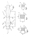
- the racket illustrated on the figure 1 which is in this case a tennis racket, comprises first a handle 2, capable of being surrounded by a not shown coating strip, also called "grip".
- This sleeve 2 is extended by a sieve 4, inside which is stretched a rope 6.
- the invention also finds application to other rackets, for which the rope 6 is replaced by a solid striking surface and rigid.
- This handle 2 firstly comprises an end cap 8, of a type known per se, which is extended by a first bulb, designated as a whole by the reference 10.
- the latter is defined by two constrictions, namely zones of smaller transverse dimension, as well as by an intermediate bulge, namely an area of larger transverse dimension.
- E 1 the end of the throat, adjacent to the plug 8
- E 2 the median throat, opposite the plug 8, and R 1 said bulge.
- the cross section of the handle 2 is of octagonal shape, as shown in FIG. figure 3 , which is a sectional view at the level of the constriction E 1 . More precisely, this octagon is defined by a rectangle 12 of length A E1 and width B E1 , which is truncated by four chamfers 14, whose length C E1 is noted.
- these chamfers 14 are oriented at 45 ° with respect to the sides of the rectangle 1.
- the four chamfers 14 have identical lengths, it being understood that they may vary on the order of a few percent of one chamfer to another.
- a R1 , B R1 and C R1 the characteristic dimensions of the handle at the bulge R 1
- a E2 , B E2 and C E2 the characteristic dimensions of the handle at the other throttle E 2 .
- this sleeve 2 increases substantially continuously, since the constriction E 1 to the bulge R 1 . This means that there may possibly be a region of the handle for which this transverse dimension is substantially constant. In a way Likewise, the transverse dimension of the shaft decreases substantially continuously from the bulge R 1 to the throttle E 2 . Finally, note that the profile of this sleeve defines, seen from the front, three tangents noted T1, T2 and T3, at each throttle and the bulge.
- l 1 is between 25 and 50 mm, preferably between 30 and 40 mm, more preferably between 34 and 36 mm, in particular equal to 35 mm.
- l 2 is between 35 and 60 mm, preferably between 45 and 55 mm, more preferably between 49 and 51 mm, in particular equal to 50 mm.
- the first bulb 10 is extended by a second bulb 20, which is defined by the aforementioned median throat E 2 , a second bulge R 2 , and a third throat E 3 , which connects the handle 2 with the sieve 4.
- this second bulb 20 has an octagonal cross section, whose dimensions vary substantially continuously from the throat E 2 to the bulge R 2 , then decrease substantially continuously this second bulge R 2 to the connection throat E 3 .
- the dimensional values of the handle, at the level of the second bulge R 2 are substantially identical to those of the first bulge R 1 , defined above. Moreover, the dimensional values of the connection throat E 3 are approximately equal to those of the end throat E 1 , also presented above.
- the length l 3 corresponding to the distance taken along the axis XX between the throat E 2 and the bulge R 2 , is between 20 and 70 mm, preferably between 40 and 50 mm, more preferably between 44 and 46 mm, in particular equal to 45 mm. Furthermore, the distance separating the bulge R 2 and the connection throat E 3 is advantageously between 20 and 70 mm.
- the invention also relates to a range of handles, whose dimensions are determined from those of the handle 2 described above.
- This sleeve 2 the dimensional characteristics of which have been presented in the foregoing, is referred to as the "standard” or "0" handle for the sake of clarity of the present description.
- this "standard" handle corresponds to a handle usually called 3 in the racket sports industry, namely that adapted to the largest number of users.
- the dimensional values of the size "-1" are linked to those of the standard size "0", in the three characteristic zones of the first bulb.
- the characteristic dimensions of a handle of size "-i" or "+ j", at the level of the second bulge R 2 are substantially identical to dimensional values of the first bulge R 1 .
- the different dimensional values of these sleeves, at the E 3 connection throat are approximately equal to those present at these sleeves, at the end of the throat E 1 .
- the invention achieves the previously mentioned objectives.
- the player is able to use the first bulb 10, for optimal grip of a racket according to the invention, for the execution of a forehand.
- the second bulb the optional character of which will be recalled, may be used by the player for the execution of the backhand, which in this case is performed with both hands.
- the handle according to the invention has at all points an octagonal section is advantageous. This allows the player to place his hands accurately, for the execution of different shots.
- the characteristic transverse dimensions of the handle according to the invention have proved advantageous, in order to provide comfort and firm grip in the player.
- the handle of the invention can significantly increase the quality of contact between the hand and the handle.
Landscapes
- Health & Medical Sciences (AREA)
- General Health & Medical Sciences (AREA)
- Physical Education & Sports Medicine (AREA)
- Physiology (AREA)
- Golf Clubs (AREA)
- Walking Sticks, Umbrellas, And Fans (AREA)
Claims (11)
- Griff (2) für einen Tennisschläger, mindestens einen ersten Wulst (10) umfassend, der von einer ersten Einschnürung oder Endeinschnürung (E1), die zum freien Ende des Griffs gerichtet ist, einer ersten Verdickung (R1) sowie einer anderen Einschnürung, genannt mittlere Einschnürung (E2) begrenzt wird, wobei dieser erste Wulst in jedem Punkt einen achteckigen Querschnitt aufweist, der von einem durch vier Schrägen (14) abgestumpften Rechteck (12) definiert wird, wobei die Schrägen, in Bezug auf die Seiten des Rechtecks, insbesondere mit einem Winkel von 45° ausgerichtet sind, und wobei die Querabmessungen dieses ersten Wulstes von jeder Einschnürung (E1, E2) aus in Richtung der Verdickung (R1) in im Wesentlichen kontinuierlicher Weise zunehmen, dadurch gekennzeichnet, dass die Querabmessungen dieses ersten Wulstes (10) die folgenden sind, wobei A und B jeweils die Länge und die Breite des Rechtecks (12) und C die Länge jeder Schräge (14) sind und A, B und C jeweils an der ersten Einschnürung (E1), der ersten Verdickung (R1) und der zweiten Einschnürung (E2)genommen werden:- AE1 zwischen 31,25 und 33,25 mm liegt,- BE1 zwischen 27 und 29 mm liegt,- CE1 zwischen 8 und 14 mm liegt,- AR1 zwischen 34,5 und 36,5 mm liegt,- BR1 zwischen 30 und 32 mm liegt,- CR1 zwischen 10 und 16 mm liegt,- AE2 zwischen 30,5 und 32,5 mm liegt,- BE2 zwischen 26,5 und 28,5 mm liegt, und- CE2 zwischen 8 und 14 mm liegt,- der Abstand (l1) längs der Hauptachse (X-X) des Griffs, zwischen der Endeinschnürung (E1) und der ersten Verdickung (R1) zwischen 25 und 50 mm liegt, in bevorzugter Weise zwischen 30 und 40 mm, in noch bevorzugterer Weise zwischen 34 und 36, insbesondere gleich 35 mm ist, und- der Abstand (l2) längs der Hauptachse (X-X) des Griffs zwischen der ersten Verdickung (R1) und der mittleren Einschnürung (E2) zwischen 35 und 60 mm liegt, in bevorzugter Weise zwischen 45 und 55, in noch bevorzugterer Weise zwischen 49 und 51, insbesondere gleich 50 mm ist.
- Griff für einen Tennisschläger nach Anspruch 1,
dadurch gekennzeichnet, dass:- AE1 zwischen 31,75 und 32,75 mm liegt, vorzugsweise zwischen 32,15 und 32,35 mm, insbesondere gleich 32,25 mm ist,- BE1 zwischen 27,5 und 28,5 mm liegt, vorzugsweise zwischen 27,9 und 28,1 mm, insbesondere gleich 28 mm ist, und- CE1 zwischen 9 und 13 mm liegt, vorzugsweise zwischen 9,75 und 12,3 mm, insbesondere gleich 11 mm ist. - Griff für einen Tennisschläger nach Anspruch 1 oder Anspruch 2, dadurch gekennzeichnet, dass:- AR1 zwischen 35 und 36 mm liegt, vorzugsweise zwischen 35,4 und 35,6 mm, insbesondere gleich 35,5 mm ist,- BR1 zwischen 30,5 und 31,5 mm liegt, vorzugsweise zwischen 30,9 und 31,1 mm, insbesondere gleich 31 mm ist, und- CR1 zwischen 11 und 14,75 mm liegt, vorzugsweise zwischen 11,5 und 14,25 mm, insbesondere gleich 13 mm ist.
- Griff eines Tennisschlägers nach einem der vorhergehenden Ansprüche, dadurch gekennzeichnet, dass:- AE2 zwischen 31 und 32 mm liegt, vorzugsweise zwischen 31,4 und 31,6 mm, insbesondere gleich 31,5 mm ist,- BE2 zwischen 27 und 28 mm liegt, vorzugsweise zwischen 27,4 und 27,6 mm, insbesondere gleich 27,5 mm ist, und- CE2 zwischen 9 und 13 mm liegt, vorzugsweise zwischen 9,4 und 12 mm, insbesondere gleich 10,7 mm ist.
- Griff eines Tennisschlägers nach einem beliebigen der vorhergehenden Ansprüche, dadurch gekennzeichnet, dass die Außenfläche des Griffs (2) an jeder Einschnürung (E1, E2) und der Verdickung (R1) drei Tangenten (T1-T3) definiert, die parallel zur Hauptachse (X-X) dieses Griffs liegen.
- Griff eines Tennisschlägers nach einem beliebigen der vorhergehenden Ansprüche, dadurch gekennzeichnet, dass dieser Griff einen zweiten Wulst (20) umfasst, der von der mittleren Einschnürung (E2), einer zweiten Verdickung (R2) sowie einer Verbindungseinschnürung (E3), die entgegengesetzt zur Endeinschnürung (E1) liegt, begrenzt wird, wobei dieser zweite Wulst (20) in jedem Punkt einen achteckigen Querschnitt aufweist, dessen Abmessungen in im Wesentlichen kontinuierlicher Weise von der mittleren Einschnürung (E2) zu der zweiten Verdickung (R2) variieren, wobei die Querabmessungen dieses Griffs an der anderen Verdickung (R2) identisch zu denen dieses Griffs an der ersten Verdickung (R1) sind.
- Griff eines Tennisschlägers nach Anspruch 6, dadurch gekennzeichnet, dass der Abstand (l3) längs der Hauptachse (X-X) des Griffs zwischen der mittleren Einschnürung (E2) und der zweiten Verdickung (R2) zwischen 20 und 70 mm liegt, in bevorzugter Weise zwischen 40 und 50 mm, in noch bevorzugter Weise zwischen 44 und 46 mm, insbesondere gleich 45 mm ist.
- Schläger, insbesondere Tennisschläger, Badmintonschläger oder Squashschläger, einen Griff entsprechend einem beliebigen der vorhergehenden Ansprüche umfassend.
- Griffsatz für einen Schläger, einen Griff nach einem beliebigen der Ansprüche 1 bis 7, genannt Standardgriff, sowie n Griff(e) umfassend, wobei n größer oder gleich 1 ist und wobei jeder Griff Querabmessungen kleiner als die des Standardgriffs aufweist, sowie auch mindestens m Griff(e) mit m größer oder gleich 1 umfassend, von denen jeder Querabmessungen aufweist, die größer als die des Standardgriffs sind, wobei die Querabmessungen jedes Griffs kleinerer Größe für jede ganze Zahl -i zwischen 1 und n definiert werden durch:AE1(-i) = AE1-iA';BE1(-i) = BE1-iB';CE1(-i) = CE1-iC';AR1(-i) = AR1-iA';BR1(-i) = BR1-iB';CR1(-i) = CR1-iC';AE2(-i) = AE2-iA';BE2(-i) = BE2-iB'; undCE2(-i) = CE2-iC',und wobei die Querabmessungen jedes Griffs größerer Größe für jede ganze Zahl j zwischen 1 und m definiert werden durch:AE1(+j) = AE1+jA';BE1(+j) = BE1+jB';CE1(+j) = CE1+jC';AR1(+j) = AR1+jA';BR1(+j) = BR1+jB';CR1(+j) = CR1+jC';AE2(+j) = AE2+jA';BE2(+j) = BE2+jB'; undCE2(+j) = CE2+jC',wobei A' und B' zwischen 0,5 und 1,5 mm und C' zwischen 0,25 und 1 mm liegen.
- Griffsatz nach dem vorhergehenden Anspruch, dadurch gekennzeichnet, dass:A' zwischen 1 und 1,3 mm liegt, insbesondere gleich 1,15 mm ist;B' zwischen 0,9 und 1,1 mm liegt, insbesondere gleich 1,0 mm ist; undC' zwischen 0,55 und 0,75 mm liegt, insbesondere gleich 0,65 mm ist.
- Schlägersatz, von dem jeder Schläger einen entsprechenden Griff umfasst, der zu dem Griffsatz nach einem der Ansprüche 9 oder 10 gehört.
Applications Claiming Priority (1)
| Application Number | Priority Date | Filing Date | Title |
|---|---|---|---|
| FR0601033A FR2896996B1 (fr) | 2006-02-06 | 2006-02-06 | Manche de raquette a caractere ergonomique, raquette, gamme de manches et gamme de raquettes correspondants |
Publications (2)
| Publication Number | Publication Date |
|---|---|
| EP1815892A1 EP1815892A1 (de) | 2007-08-08 |
| EP1815892B1 true EP1815892B1 (de) | 2009-04-01 |
Family
ID=36860473
Family Applications (1)
| Application Number | Title | Priority Date | Filing Date |
|---|---|---|---|
| EP07356014A Not-in-force EP1815892B1 (de) | 2006-02-06 | 2007-02-05 | Schlägergriff mit ergonomischer Schlägereigenschaft, entsprechendes Griffsortiment und Schlägersortiment |
Country Status (6)
| Country | Link |
|---|---|
| EP (1) | EP1815892B1 (de) |
| JP (1) | JP2007209753A (de) |
| CN (1) | CN101015736B (de) |
| DE (1) | DE602007000789D1 (de) |
| ES (1) | ES2322676T3 (de) |
| FR (1) | FR2896996B1 (de) |
Families Citing this family (2)
| Publication number | Priority date | Publication date | Assignee | Title |
|---|---|---|---|---|
| JP6573411B1 (ja) * | 2018-06-11 | 2019-09-11 | 竹内 知子 | ラケット |
| JP7730441B1 (ja) * | 2025-04-30 | 2025-08-27 | コクリョウ 市村 | 小学生から成人までに対応するバドミントンとソフトバドミントン用ラケットセット |
Family Cites Families (7)
| Publication number | Priority date | Publication date | Assignee | Title |
|---|---|---|---|---|
| US259448A (en) * | 1882-06-13 | woodhouse | ||
| DE3414293A1 (de) * | 1984-04-14 | 1985-10-24 | Horst 8502 Zirndorf Kleylein | Griff fuer sportgeraete |
| DE8608907U1 (de) * | 1986-05-14 | 1986-07-17 | Berger, Bernhard, 8458 Sulzbach Rosenberg | Tennisschläger |
| DE8707162U1 (de) * | 1987-05-19 | 1987-10-01 | Kleylein, Horst, 8500 Nürnberg | Griff für Tennisschläger od.dgl. |
| DE9015507U1 (de) * | 1990-11-13 | 1991-03-21 | Kleylein, Horst, 8500 Nürnberg | Baseballschläger |
| BR9600897A (pt) * | 1996-02-15 | 1999-12-07 | Bernardo Andrade Nogueira | Empunhadura e/ou cabo manual anatÈmico-isobárico e seu processo de fabricação |
| SE521900C2 (sv) * | 2002-10-08 | 2003-12-16 | Attila Szelenyi | Racketskaft samt med sådant skaftförsedd racket |
-
2006
- 2006-02-06 FR FR0601033A patent/FR2896996B1/fr not_active Expired - Fee Related
-
2007
- 2007-02-05 DE DE602007000789T patent/DE602007000789D1/de active Active
- 2007-02-05 ES ES07356014T patent/ES2322676T3/es active Active
- 2007-02-05 EP EP07356014A patent/EP1815892B1/de not_active Not-in-force
- 2007-02-06 CN CN2007100065701A patent/CN101015736B/zh not_active Expired - Fee Related
- 2007-02-06 JP JP2007026635A patent/JP2007209753A/ja active Pending
Also Published As
| Publication number | Publication date |
|---|---|
| CN101015736A (zh) | 2007-08-15 |
| CN101015736B (zh) | 2010-06-16 |
| ES2322676T3 (es) | 2009-06-24 |
| JP2007209753A (ja) | 2007-08-23 |
| FR2896996B1 (fr) | 2008-03-14 |
| DE602007000789D1 (de) | 2009-05-14 |
| EP1815892A1 (de) | 2007-08-08 |
| FR2896996A1 (fr) | 2007-08-10 |
Similar Documents
| Publication | Publication Date | Title |
|---|---|---|
| EP0611316B1 (de) | Ausgeglichener golfclub | |
| EP2099536A1 (de) | Schlägergriffeinsatz und entsprechender griff sowie schläger | |
| FR2681791A1 (fr) | Dispositif d'amortissement des vibrations pour club de golf. | |
| EP0241393B1 (de) | Vorrichtung zum Dämpfen der Schwingungen einer Schlägerbespannung | |
| WO2011021060A1 (fr) | Poignée pour guidon d'un véhicule à deux roues | |
| EP1815892A1 (de) | Schlägergriff mit ergonomischer Schlägereigenschaft, entsprechendes Griffsortiment und Schlägersortiment | |
| FR2660202A1 (fr) | Jeu de clubs de golf. | |
| EP0855201B1 (de) | Gleitbrett | |
| FR2942141A1 (fr) | Raquette de tennis comprenant des moyens d'amortissement | |
| EP0501895A1 (de) | Schläger mit länglicher Asymmetrie | |
| FR2615401A1 (fr) | Raquette presentant un col perfectionne | |
| FR2682607A1 (fr) | Perfectionnement pour club de golf. | |
| FR2858241A3 (fr) | Raquette dotee d'une aptitude a absorber les vibrations | |
| EP2490774B1 (de) | Überzugselement für einen schlägergriff, überzugsset, überzug und entsprechendes verfahren | |
| US20070191155A1 (en) | Racket handle of ergonomic character, a racket, and corresponding ranges of handles and of rackets | |
| FR2689228A1 (fr) | Flèche pour arc et son procédé de fabrication. | |
| EP2758137B1 (de) | Griff für badmintonschläger und zugehöriges herstellungsverfahren | |
| FR2668073A1 (fr) | Cadre de raquette a caracteristiques d'amortissement des chocs. | |
| FR2467321A1 (fr) | Moyen d'accouplement de deux arbres | |
| EP2889062A1 (de) | Tischtennisschläger | |
| EP1008511A1 (de) | Fahrrad mit profilierten Haltegriffen | |
| FR3014323A1 (fr) | Raquette de tennis de table comportant un renfort | |
| FR2983823A1 (fr) | Guidon pour un vehicule | |
| FR2608443A1 (fr) | Raquette de sport comportant un manche perfectionne | |
| FR2567291A1 (fr) | Poignee de prehension d'outil ou organe de commande, notamment pour whisbone |
Legal Events
| Date | Code | Title | Description |
|---|---|---|---|
| PUAI | Public reference made under article 153(3) epc to a published international application that has entered the european phase |
Free format text: ORIGINAL CODE: 0009012 |
|
| AK | Designated contracting states |
Kind code of ref document: A1 Designated state(s): AT BE BG CH CY CZ DE DK EE ES FI FR GB GR HU IE IS IT LI LT LU LV MC NL PL PT RO SE SI SK TR |
|
| AX | Request for extension of the european patent |
Extension state: AL BA HR MK YU |
|
| 17P | Request for examination filed |
Effective date: 20071220 |
|
| 17Q | First examination report despatched |
Effective date: 20080207 |
|
| AKX | Designation fees paid |
Designated state(s): DE ES FR GB IT |
|
| GRAP | Despatch of communication of intention to grant a patent |
Free format text: ORIGINAL CODE: EPIDOSNIGR1 |
|
| GRAS | Grant fee paid |
Free format text: ORIGINAL CODE: EPIDOSNIGR3 |
|
| GRAA | (expected) grant |
Free format text: ORIGINAL CODE: 0009210 |
|
| AK | Designated contracting states |
Kind code of ref document: B1 Designated state(s): DE ES FR GB IT |
|
| REG | Reference to a national code |
Ref country code: GB Ref legal event code: FG4D Free format text: NOT ENGLISH |
|
| REF | Corresponds to: |
Ref document number: 602007000789 Country of ref document: DE Date of ref document: 20090514 Kind code of ref document: P |
|
| REG | Reference to a national code |
Ref country code: ES Ref legal event code: FG2A Ref document number: 2322676 Country of ref document: ES Kind code of ref document: T3 |
|
| PLBE | No opposition filed within time limit |
Free format text: ORIGINAL CODE: 0009261 |
|
| STAA | Information on the status of an ep patent application or granted ep patent |
Free format text: STATUS: NO OPPOSITION FILED WITHIN TIME LIMIT |
|
| 26N | No opposition filed |
Effective date: 20100105 |
|
| PGRI | Patent reinstated in contracting state [announced from national office to epo] |
Ref country code: IT Effective date: 20110501 |
|
| REG | Reference to a national code |
Ref country code: FR Ref legal event code: PLFP Year of fee payment: 10 |
|
| PGFP | Annual fee paid to national office [announced via postgrant information from national office to epo] |
Ref country code: IT Payment date: 20160212 Year of fee payment: 10 Ref country code: DE Payment date: 20160212 Year of fee payment: 10 Ref country code: ES Payment date: 20160301 Year of fee payment: 10 |
|
| PGFP | Annual fee paid to national office [announced via postgrant information from national office to epo] |
Ref country code: GB Payment date: 20160216 Year of fee payment: 10 |
|
| REG | Reference to a national code |
Ref country code: FR Ref legal event code: PLFP Year of fee payment: 11 |
|
| REG | Reference to a national code |
Ref country code: DE Ref legal event code: R119 Ref document number: 602007000789 Country of ref document: DE |
|
| GBPC | Gb: european patent ceased through non-payment of renewal fee |
Effective date: 20170205 |
|
| REG | Reference to a national code |
Ref country code: FR Ref legal event code: PLFP Year of fee payment: 12 |
|
| PG25 | Lapsed in a contracting state [announced via postgrant information from national office to epo] |
Ref country code: DE Free format text: LAPSE BECAUSE OF NON-PAYMENT OF DUE FEES Effective date: 20170901 |
|
| PG25 | Lapsed in a contracting state [announced via postgrant information from national office to epo] |
Ref country code: IT Free format text: LAPSE BECAUSE OF NON-PAYMENT OF DUE FEES Effective date: 20170205 Ref country code: GB Free format text: LAPSE BECAUSE OF NON-PAYMENT OF DUE FEES Effective date: 20170205 |
|
| REG | Reference to a national code |
Ref country code: ES Ref legal event code: FD2A Effective date: 20180704 |
|
| PG25 | Lapsed in a contracting state [announced via postgrant information from national office to epo] |
Ref country code: ES Free format text: LAPSE BECAUSE OF NON-PAYMENT OF DUE FEES Effective date: 20170206 |
|
| PGFP | Annual fee paid to national office [announced via postgrant information from national office to epo] |
Ref country code: FR Payment date: 20240112 Year of fee payment: 18 |
|
| PG25 | Lapsed in a contracting state [announced via postgrant information from national office to epo] |
Ref country code: FR Free format text: LAPSE BECAUSE OF NON-PAYMENT OF DUE FEES Effective date: 20250228 |