EP1815933A2 - Kühlflüssigkeitsverarbeitungsvorrichtung für eine elektrische Drahterodiermaschine - Google Patents
Kühlflüssigkeitsverarbeitungsvorrichtung für eine elektrische Drahterodiermaschine Download PDFInfo
- Publication number
- EP1815933A2 EP1815933A2 EP07250277A EP07250277A EP1815933A2 EP 1815933 A2 EP1815933 A2 EP 1815933A2 EP 07250277 A EP07250277 A EP 07250277A EP 07250277 A EP07250277 A EP 07250277A EP 1815933 A2 EP1815933 A2 EP 1815933A2
- Authority
- EP
- European Patent Office
- Prior art keywords
- machining
- machining liquid
- temperature
- tank
- water tank
- Prior art date
- Legal status (The legal status is an assumption and is not a legal conclusion. Google has not performed a legal analysis and makes no representation as to the accuracy of the status listed.)
- Withdrawn
Links
- 238000003754 machining Methods 0.000 title claims abstract description 265
- 239000007788 liquid Substances 0.000 title claims abstract description 185
- XLYOFNOQVPJJNP-UHFFFAOYSA-N water Substances O XLYOFNOQVPJJNP-UHFFFAOYSA-N 0.000 claims abstract description 52
- 238000001816 cooling Methods 0.000 claims abstract description 32
- 239000002351 wastewater Substances 0.000 claims description 12
- 238000010586 diagram Methods 0.000 description 5
- 230000008602 contraction Effects 0.000 description 3
- 238000010438 heat treatment Methods 0.000 description 1
- 238000009413 insulation Methods 0.000 description 1
Images

Classifications
-
- B—PERFORMING OPERATIONS; TRANSPORTING
- B23—MACHINE TOOLS; METAL-WORKING NOT OTHERWISE PROVIDED FOR
- B23H—WORKING OF METAL BY THE ACTION OF A HIGH CONCENTRATION OF ELECTRIC CURRENT ON A WORKPIECE USING AN ELECTRODE WHICH TAKES THE PLACE OF A TOOL; SUCH WORKING COMBINED WITH OTHER FORMS OF WORKING OF METAL
- B23H1/00—Electrical discharge machining, i.e. removing metal with a series of rapidly recurring electrical discharges between an electrode and a workpiece in the presence of a fluid dielectric
- B23H1/10—Supply or regeneration of working media
-
- B—PERFORMING OPERATIONS; TRANSPORTING
- B23—MACHINE TOOLS; METAL-WORKING NOT OTHERWISE PROVIDED FOR
- B23H—WORKING OF METAL BY THE ACTION OF A HIGH CONCENTRATION OF ELECTRIC CURRENT ON A WORKPIECE USING AN ELECTRODE WHICH TAKES THE PLACE OF A TOOL; SUCH WORKING COMBINED WITH OTHER FORMS OF WORKING OF METAL
- B23H7/00—Processes or apparatus applicable to both electrical discharge machining and electrochemical machining
- B23H7/36—Supply or regeneration of working media
Definitions
- the present invention relates to improvement of a machining liquid processing apparatus provided to a wire electric discharge machine and for controlling a temperature of machining liquid.
- a wire electric discharge machine is for machining a workpiece (object to be machined) by applying a voltage between a wire electrode and the workpiece to generate electric discharge.
- the machining liquid is interposed between the wire electrode and the workpiece.
- the machining liquid is heated and a temperature of the machining liquid is raised by the electric discharge between the wire electrode and the workpiece.
- the temperature rises due to heat loss of a pump for supplying the machining liquid to a machining tank or the like in which the workpiece is disposed.
- the wire electric discharge machine includes a cooling device for cooling the machining liquid.
- FIG. 2 is a schematic drawing of a prior-art machining liquid processing apparatus employed in a wire electric discharge machine and for controlling a temperature of machining liquid.
- reference numeral 1 denotes a mechanism portion of a wire electric discharge machine
- a table (not shown) on which a workpiece is placed is disposed in a machining tank 2 disposed on the mechanism portion 1
- a wire electrode (not shown) travels in the machining tank 2.
- the table is driven by a feed servomotor or the like provided to the mechanism portion 1 and a voltage is applied between the wire electrode and the workpiece to generate electric discharge to thereby carry out electric discharge machining.
- Machining liquid is stored in the machining tank 2 and is heated and warmed by the electric discharge.
- the machining liquid including machining chips flows out of the machining tank 2 and is collected and stored in a waste water tank 3.
- the machining liquid in the waste water tank 3 is drawn up by a filter pump P1, filtered by a filter F, and then supplied into and stored in a clean water tank 4.
- the machining liquid in the clean water tank 4 is drawn up by a circulation pump P3 and introduced into a machining liquid cooling device 6 through a machining liquid supply path L1a.
- the machining liquid cooling device 6 carries out temperature control based on a temperature detected by a temperature sensor S1 for detecting the temperature of the machining liquid from the clean water tank 4 to cool the machining liquid to a predetermined temperature.
- the cooled machining liquid is supplied to the machining tank 2 through a machining liquid supply path L1b.
- the machining liquid in the clean water tank 4 is drawn up by a jet pump P2 through a machining liquid supply path L2a and supplied to upper and lower wire guides 5 through a machining liquid supply path L2b. In this way, the machining liquid is jetted toward a gap between the wire electrode and the workpiece from nozzles provided to the wire guides 5.
- the machining liquid is circulated and used as described above.
- the machining liquid cooled by the machining liquid cooling device 6 is supplied and also the relatively high-temperature machining liquid of the clean water tank 4 and not subjected to cooling treatment is supplied from the upper and lower wire guides 5.
- the machining liquid cooling device 6 is of an on/off control type, contraction due to the thermal deformation is large. Although this has a small influence in a case of an inverter-type cooling device, the thermal deformation of the table and the workpiece and the contraction due to the thermal deformation affect machining accuracy.
- FIG. 3 is a schematic drawing of the machining liquid processing apparatus described in Japanese Patent Application Laid-Open No. 8-174339 .
- the machining liquid flowing out of the machining tank 2 is collected and stored in a waste water tank 3.
- the machining liquid in the waste water tank 3 is drawn up by a filter pump P1, filtered by a filter F, and lead into the clean water tank 4.
- the machining liquid stored in the clean water tank 4 is drawn up by a circulation pump P3 through a machining liquid supply path L1a and is lead to a machining liquid cooling device 6 through one of branch discharge ports of the pump P3.
- the machining liquid cooling device 6 controls the machining liquid to a predetermined temperature and returns the machining liquid into the clean water tank 4 through a machining liquid return path L1c.
- the machining liquid is supplied into the machining tank 2 through the machining liquid supply path L1b. Moreover, the machining liquid drawn up from the clean water tank 4 by a jet pump through a machining liquid supply path L2a is supplied to the upper and lower wire guides 5 through a machining liquid supply path L2b and is jetted toward the gap between the wire electrode and the workpiece.
- the machining liquid stored in the clean water tank 4 is sent into the machining liquid cooling device 6 and controlled to the predetermined temperature there.
- the machining liquid is supplied to the machining tank 2 and the upper and lower wire guides 5 (gap between the wire electrode and the workpiece) through the circulation pump P3 and the jet pump P2, respectively, and therefore the machining liquid is heated and the temperature of the machining liquid rises due to heat loss of the pumps P3 and P2. Therefore, the machining liquid the temperature of which is not controlled is supplied into the machining tank 2 and the gap between the wire electrode and the workpiece.
- the machining liquid supplied into the machining tank 2 through the machining liquid supply path L1b has been heated and the temperature of the machining liquid has been raised by the circulation pump P3, having not undergone temperature control.
- the machining liquid supplied to the upper and lower wire guides 5 through the machining liquid supply path L2b has been heated and the temperature of the machining liquid has been raised by the jet pump P2, having not undergone temperature control.
- the temperature of the machining liquid in the machining tank 2 rises and also becomes nonuniform.
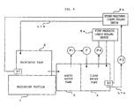
- FIG. 4 There is also another known machining liquid processing apparatus for controlling a temperature of the machining liquid as shown in FIG. 4.
- Machining liquid in a machining tank 2 flows into and is stored in a waste water tank 3.
- the machining liquid in the waste water tank 3 is drawn up by a filter pump P1, filtered by a filter F, and is then supplied into a clean water tank 4.
- the machining liquid stored in the clean water tank 4 is drawn up into a first machining liquid cooling device 6a by a pump P4.
- the first machining liquid cooling device 6a controls the temperature of the machining liquid based on a temperature detected by a sensor S2 for detecting the temperature of the machining liquid in the clean water tank 4 and returns the machining liquid into the clean water tank 4. In this way, the temperature of the machining liquid in the clean water tank 4 is controlled.
- the machining liquid stored in the clean water tank 4 is drawn up to into a second machining liquid cooling device 6b by a circulation pump P3.
- the second machining liquid cooling device 6b controls the temperature of the machining liquid based on the detected temperature from a temperature sensor S1 for detecting the temperature of the machining liquid in the machining tank 2 and supplies the machining liquid to the machining tank 2 (see Japanese Patent Application Laid-Open No. 2-95519 , Japanese Patent Application Laid-Open No. 2005-335027 ).
- the temperature of the machining liquid in the machining tank 2 is not controlled and the cooled machining liquid is directly supplied into the machining tank 2 and also the machining liquid which has not been cooled is supplied into the machining tank 2 from the upper and lower wire guides 5. Therefore, the temperature of the machining liquid in the machining tank 2 is unstable and nonuniform, which promotes contraction of the table and work in the machining tank 2 due to thermal deformation to thereby reduce the machining accuracy or cause a break in the wire electrode.
- the cooled machining liquid at the controlled temperature in the clean water tank 4 is supplied into the machining tank 2 and to between the wire electrode and the workpiece through upper and lower wire guides 5 by the circulation pump P3 and the jet pump P2. Because the machining liquid which has been heated and the temperature of which has been raised by the heat loss of the circulation pump P3 or the jet pump P2 is supplied into the machining tank 2, the temperature of the machining liquid in the machining tank 2 rises and it is impossible to obtain a uniform and constant temperature.
- the present invention relates to a machining liquid processing apparatus in a wire electric discharge machine.
- the wire electric discharge machine includes: a machining tank having in itself an electric discharge machining portion for carrying out electric discharge machining of an object to be machined by using a wire electrode; a waste water tank for collecting and storing the machining liquid in the machining tank; a clean water tank for storing the machining liquid from the waste water tank and filtered by a filter; a machining liquid supply path for supplying the machining liquid in the clean water tank into the machining tank; and a supply path for supplying the machining liquid in the clean water tank to upper and lower wire guides.
- the machining liquid processing apparatus includes a machining liquid cooling device for cooling the machining liquid in the clean water tank and supplying the machining liquid into the clean water tank; and a temperature detecting means provided to the machining tank.
- the machining liquid cooling device controls a temperature in the clean water tank based on a machining liquid temperature in the machining tank and detected by the temperature detecting means to thereby suppress fluctuations in the machining liquid temperature in the machining tank and make the temperature uniform.
- the machining liquid processing apparatus in the wire electric discharge machine capable of being structured at low cost, suppressing the fluctuations in the machining liquid temperature in the machining tank, and maintaining the temperature uniform. Because the machining liquid temperature in the machining tank is maintained substantially at a predetermined value and uniform, it is possible to suppress thermal deformation of the object to be machined and the table mounted with the object to be machined and caused by the fluctuations in the temperature of the machining liquid to thereby enhance machining accuracy and suppress a break in the wire electrode.
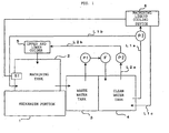
- FIG. 1 is a schematic block diagram of a machining liquid processing apparatus of an embodiment of the present invention. Components similar to those of the prior-art machining liquid processing apparatuses are provided with similar reference numerals.
- a machining tank 2 is provided to a mechanism portion 1 of a wire electric discharge machine and an electric discharge machining portion is installed in the machining tank 2.
- a workpiece object to be machined
- a wire electrode (not shown) is moved with respect to the workpiece while applying a voltage between the workpiece and the wire electrode to generate electric discharge to thereby carry out electric discharge machining of the workpiece.
- the machining liquid is supplied and stored.
- the machining liquid in the machining tank 2 includes machining chips and the like produced by the electric discharge and the machining liquid flows out into a waste water tank 3.
- the machining liquid collected and stored in the waste water tank 3 is drawn up by a filter pump P1, filtered by a filter F to remove the machining chips and the like, and supplied into a clean water tank 4.
- the machining liquid stored in the clean water tank 4 is drawn up by a circulation pump P3 through a machining liquid supply path L1a and branches into discharge ports of the pump P3. From one of the branch discharge ports, the machining liquid is supplied to the machining tank 2 through the machining liquid supply path L1b. From the other, the machining liquid is supplied to a machining liquid cooling device 6, controlled by cooling, and returned to the clean water tank 4 through a machining liquid return path L1c.
- the machining tank 2 has a temperature sensor S1 for detecting a temperature of the machining liquid in the machining tank 2.
- the temperature of the machining liquid detected by the temperature sensor S1 is input to the machining liquid cooling device 6.
- the machining liquid cooling device 6 controls the temperature of the machining liquid to a predetermined temperature based on the temperature of machining liquid detected by this temperature sensor S1 and returns the machining liquid to the clean water tank 4 through the machining liquid return path L1c.
- the machining liquid stored in the clean water tank 4 is drawn up by a jet pump P2 through a machining liquid supply path L2a and supplied to upper and lower wire guides 5 through a machining liquid supply path L2b.
- the machining liquid is jetted toward a gap between the wire electrode and the workpiece from nozzles provided to the wire guides 5 to cool the gap in this way, the machining chips produced by the electric discharge are removed from the gap.
- the machining liquid in the clean water tank 4 is controlled by the machining liquid cooling device 6 based on the temperature of the machining liquid in the machining tank 2 detected by the temperature sensor S1, the machining liquid in the clean water tank 4 is maintained at the predetermined temperature.
- the machining liquid in the clean water tank 4, which has undergone temperature control, is supplied by the circulation pump P3 and the jet pump P2 into the machining tank 2 directly or through the upper and lower wire guides 5.
- the machining liquid directly supplied from the clean water tank 4 into the machining tank 2 and the machining liquid supplied from the clean water tank 4 into the machining tank 2 through the upper and lower wire guides 5 are heated and their temperatures are raised by heat loss of the circulation pump P3 and the jet pump P2, respectively.
- the machining liquid in the clean water tank 4 which has been controlled to the same temperature, is supplied by the circulation pump P3 or the jet pump P2
- the temperature of the machining liquid directly supplied from the clean water tank 4 into the machining tank 2 and the temperature of the machining liquid supplied from the clean water tank 4 into the machining tank 2 through the upper and lower wire guides 5 are substantially the same and no significant temperature difference arises and therefore the machining liquid in the machining tank 2 is maintained at the substantially uniform and constant temperature.
- the temperature of the machining liquid charged into the machining tank 2 rises by a temperature corresponding to heating by the circulation pump P3 or the jet pump P2 and therefore the machining liquid cooling device 6 needs to control the temperature of the machining liquid in the clean water tank 4 to a temperature lower than a target temperature of the machining liquid in the machining tank 2 by the temperature rise due to the circulation pump P3 and the jet pump P2.
- a target controlled temperature of the machining liquid temperature in the clean water tank 4 by the machining liquid cooling device 6 is set to a temperature lower than the target machining liquid temperature in the machining tank 2 by the temperature rise due to the circulation pump P3 and the jet pump P2. Then, by using a temperature lower than the machining liquid temperature detected by the temperature sensor S1 by the temperature rise due to the circulation pump P3 and the jet pump P2 as a detected temperature, the machining liquid cooling device 6 carries out the control so that the detected temperature agrees with the target temperature. As a result, the machining liquid stored in the clean water tank 4 is controlled and maintained at the temperature lower than the target temperature of the machining liquid in the machining tank 2 by the temperature rise due to the circulation pump P3 and the jet pump P2. Then, the machining liquid in the clean water tank 4 is heated by the circulation pump P3 and the jet pump P2 to the target temperature of the machining liquid in the machining tank 2 and is supplied to the machining tank 2.
Landscapes
- Engineering & Computer Science (AREA)
- Mechanical Engineering (AREA)
- Chemical & Material Sciences (AREA)
- Chemical Kinetics & Catalysis (AREA)
- Electrochemistry (AREA)
- Electrical Discharge Machining, Electrochemical Machining, And Combined Machining (AREA)
Applications Claiming Priority (1)
| Application Number | Priority Date | Filing Date | Title |
|---|---|---|---|
| JP2006024869A JP2007203408A (ja) | 2006-02-01 | 2006-02-01 | ワイヤ放電加工機の加工液処理装置 |
Publications (1)
| Publication Number | Publication Date |
|---|---|
| EP1815933A2 true EP1815933A2 (de) | 2007-08-08 |
Family
ID=38080892
Family Applications (1)
| Application Number | Title | Priority Date | Filing Date |
|---|---|---|---|
| EP07250277A Withdrawn EP1815933A2 (de) | 2006-02-01 | 2007-01-23 | Kühlflüssigkeitsverarbeitungsvorrichtung für eine elektrische Drahterodiermaschine |
Country Status (4)
| Country | Link |
|---|---|
| US (1) | US20070175814A1 (de) |
| EP (1) | EP1815933A2 (de) |
| JP (1) | JP2007203408A (de) |
| CN (1) | CN101011764A (de) |
Cited By (1)
| Publication number | Priority date | Publication date | Assignee | Title |
|---|---|---|---|---|
| CN103906594A (zh) * | 2012-10-30 | 2014-07-02 | 三菱电机株式会社 | 线电极放电加工机及冷却控制装置 |
Families Citing this family (11)
| Publication number | Priority date | Publication date | Assignee | Title |
|---|---|---|---|---|
| US20050218089A1 (en) * | 2004-03-30 | 2005-10-06 | General Electric Company | Flushing and filtering system for electroerosion machining |
| JP4153534B2 (ja) * | 2006-05-30 | 2008-09-24 | ファナック株式会社 | ワイヤ放電加工機 |
| KR200445828Y1 (ko) * | 2007-10-15 | 2009-09-03 | 주식회사마스타텍 | 가공유 처리 장치 |
| EP2422910B1 (de) | 2010-08-25 | 2015-09-16 | Fanuc Corporation | Drahterodiermaschine mit Funktion zur automatischen Umschaltung zwischen Konstanttemperaturregelung und Differenztemperaturregelung |
| JP5568117B2 (ja) | 2012-09-21 | 2014-08-06 | ファナック株式会社 | 放電加工機の加工液供給装置 |
| JP5870143B2 (ja) * | 2014-04-03 | 2016-02-24 | ファナック株式会社 | 上下ガイドの熱変位補正機能を有するワイヤ放電加工機 |
| JP6110353B2 (ja) | 2014-10-06 | 2017-04-05 | ファナック株式会社 | フィルタの交換時期の予測機能を有するワイヤ放電加工機 |
| CN105345185A (zh) * | 2015-11-11 | 2016-02-24 | 安徽天思朴超精密模具股份有限公司 | 线切割液输送系统 |
| CN106270852A (zh) * | 2016-08-26 | 2017-01-04 | 灵璧县灵磁新材料有限公司 | 一种磁泥分离机 |
| JP6444959B2 (ja) * | 2016-11-01 | 2018-12-26 | ファナック株式会社 | ワイヤ放電加工機 |
| CN110860746B (zh) * | 2019-11-20 | 2020-10-16 | 益模钢模五金(深圳)有限公司 | 带有工作液处理结构的线割机 |
Family Cites Families (2)
| Publication number | Priority date | Publication date | Assignee | Title |
|---|---|---|---|---|
| JP2640682B2 (ja) * | 1988-10-27 | 1997-08-13 | ファナック株式会社 | ワイヤ放電加工装置の加工液温度の異常表示方式 |
| JP2005335027A (ja) * | 2004-05-28 | 2005-12-08 | Fanuc Ltd | 放電加工機、及び加工液冷却装置 |
-
2006
- 2006-02-01 JP JP2006024869A patent/JP2007203408A/ja active Pending
-
2007
- 2007-01-23 EP EP07250277A patent/EP1815933A2/de not_active Withdrawn
- 2007-01-29 US US11/699,022 patent/US20070175814A1/en not_active Abandoned
- 2007-01-31 CN CNA2007100069609A patent/CN101011764A/zh active Pending
Cited By (2)
| Publication number | Priority date | Publication date | Assignee | Title |
|---|---|---|---|---|
| CN103906594A (zh) * | 2012-10-30 | 2014-07-02 | 三菱电机株式会社 | 线电极放电加工机及冷却控制装置 |
| CN103906594B (zh) * | 2012-10-30 | 2017-05-10 | 三菱电机株式会社 | 线电极放电加工机及冷却控制装置 |
Also Published As
| Publication number | Publication date |
|---|---|
| CN101011764A (zh) | 2007-08-08 |
| US20070175814A1 (en) | 2007-08-02 |
| JP2007203408A (ja) | 2007-08-16 |
Similar Documents
| Publication | Publication Date | Title |
|---|---|---|
| EP1815933A2 (de) | Kühlflüssigkeitsverarbeitungsvorrichtung für eine elektrische Drahterodiermaschine | |
| EP1862245B1 (de) | Drahtfunkenerosionsmaschine | |
| KR20110031084A (ko) | 가공조 내로의 가공액의 공급량을 제어하여 액온 일정 제어를 실시하는 와이어 컷 방전 가공기 | |
| KR20170102817A (ko) | 정온수 공급 장치 | |
| CN102407391A (zh) | 具有自动切换恒温控制和温差控制的功能的电火花线切割加工机 | |
| JP2010115757A (ja) | 加工液温度制御機能を有するワイヤカット放電加工機 | |
| JP2010284723A (ja) | 研削装置のクーラント装置 | |
| US5760361A (en) | Multiple single phase weld control systems from a polyphase power source | |
| US11318577B2 (en) | System and method of delivering slurry for chemical mechanical polishing | |
| KR900006223B1 (ko) | 방전 가공 장치 | |
| JPS6342981Y2 (de) | ||
| US9409246B2 (en) | Wire electric discharge machining apparatus and cooling control device | |
| US20050265854A1 (en) | Electric discharge machine and machining fluid cooling device | |
| JPS61293729A (ja) | ワイヤ放電加工装置 | |
| JP4864960B2 (ja) | ワイヤ放電加工装置 | |
| TW202537747A (zh) | 機台水槽加工區恆溫控制裝置 | |
| EP4342613A1 (de) | Funkenerosionsmaschine und funkenerosionsverfahren | |
| JP3674340B2 (ja) | 放電加工機 | |
| JPH10235520A (ja) | 形彫り放電加工用の電極および形彫り放電加工機 | |
| CN103252546A (zh) | 加工槽内相对高温液体区温控方法及装置 | |
| JPS63120038A (ja) | ワイヤカツト放電加工機における加工液温度制御装置 | |
| JP2025139328A (ja) | 加工水供給装置 | |
| JPS62114825A (ja) | 温度制御回路を備えた放電加工装置 | |
| CN121324438A (zh) | 一种应用于火花机的电导率监测系统和方法、火花机系统 | |
| KR19990054312A (ko) | 용접냉각수의 항온/등저항 시스템 |
Legal Events
| Date | Code | Title | Description |
|---|---|---|---|
| PUAI | Public reference made under article 153(3) epc to a published international application that has entered the european phase |
Free format text: ORIGINAL CODE: 0009012 |
|
| AK | Designated contracting states |
Kind code of ref document: A2 Designated state(s): AT BE BG CH CY CZ DE DK EE ES FI FR GB GR HU IE IS IT LI LT LU LV MC NL PL PT RO SE SI SK TR |
|
| AX | Request for extension of the european patent |
Extension state: AL BA HR MK YU |
|
| STAA | Information on the status of an ep patent application or granted ep patent |
Free format text: STATUS: THE APPLICATION HAS BEEN WITHDRAWN |
|
| 18W | Application withdrawn |
Effective date: 20080116 |