EP1815985A1 - Procédé de contrôle de ton de couleur de motif et contrôleur - Google Patents
Procédé de contrôle de ton de couleur de motif et contrôleur Download PDFInfo
- Publication number
- EP1815985A1 EP1815985A1 EP05806335A EP05806335A EP1815985A1 EP 1815985 A1 EP1815985 A1 EP 1815985A1 EP 05806335 A EP05806335 A EP 05806335A EP 05806335 A EP05806335 A EP 05806335A EP 1815985 A1 EP1815985 A1 EP 1815985A1
- Authority
- EP
- European Patent Office
- Prior art keywords
- color
- tone values
- density value
- solid density
- density
- Prior art date
- Legal status (The legal status is an assumption and is not a legal conclusion. Google has not performed a legal analysis and makes no representation as to the accuracy of the status listed.)
- Withdrawn
Links
Images


Classifications
-
- B—PERFORMING OPERATIONS; TRANSPORTING
- B41—PRINTING; LINING MACHINES; TYPEWRITERS; STAMPS
- B41F—PRINTING MACHINES OR PRESSES
- B41F31/00—Inking arrangements or devices
- B41F31/02—Ducts, containers, supply or metering devices
- B41F31/04—Ducts, containers, supply or metering devices with duct-blades or like metering devices
- B41F31/045—Remote control of the duct keys
-
- B—PERFORMING OPERATIONS; TRANSPORTING
- B41—PRINTING; LINING MACHINES; TYPEWRITERS; STAMPS
- B41F—PRINTING MACHINES OR PRESSES
- B41F33/00—Indicating, counting, warning, control or safety devices
- B41F33/0036—Devices for scanning or checking the printed matter for quality control
- B41F33/0045—Devices for scanning or checking the printed matter for quality control for automatically regulating the ink supply
-
- G—PHYSICS
- G01—MEASURING; TESTING
- G01N—INVESTIGATING OR ANALYSING MATERIALS BY DETERMINING THEIR CHEMICAL OR PHYSICAL PROPERTIES
- G01N21/00—Investigating or analysing materials by the use of optical means, i.e. using sub-millimetre waves, infrared, visible or ultraviolet light
- G01N21/17—Systems in which incident light is modified in accordance with the properties of the material investigated
- G01N21/25—Colour; Spectral properties, i.e. comparison of effect of material on the light at two or more different wavelengths or wavelength bands
-
- H—ELECTRICITY
- H04—ELECTRIC COMMUNICATION TECHNIQUE
- H04N—PICTORIAL COMMUNICATION, e.g. TELEVISION
- H04N1/00—Scanning, transmission or reproduction of documents or the like, e.g. facsimile transmission; Details thereof
- H04N1/40—Picture signal circuits
- H04N1/407—Control or modification of tonal gradation or of extreme levels, e.g. background level
Definitions
- This invention relates to a picture color tone controlling method and apparatus for a printing press, and more particularly to a picture color tone controlling method and apparatus for controlling the color tone using an IRGB densitometer.
- color tone control is performed in such a procedure as described below.
- a spectral reflectance of a picture printed by printing units of different colors is measured by a spectrometer. Then, the spectral reflectance (average spectral reflectance in an overall key zone) is arithmetically operated for each of key zones of ink keys, and the spectral reflectance of each key zone is converted into a color coordinate value (L*a*b*) proposed by the International Commission on Illumination. If the ink supplying amount for each color is adjusted and test printing is performed and then a printing sheet (hereinafter referred to as OK sheet) having a desired color tone is obtained, then the color coordinate value for each key zone of the OK sheet is set as a target color coordinate value.
- OK sheet a printing sheet having a desired color tone
- actual printing is started, and the difference (color difference) between the color coordinate values of the OK sheet and a printing sheet (printing sheet obtained by actual printing is hereinafter referred to as actual printing sheet) is calculated for each of the key zones. Thereafter, an increasing and decreasing amount for the opening of the ink key of each printing unit with respect to the color difference is calculated, and the opening of each ink key of each printing unit is adjusted by online control so that the color difference may be reduced to zero.
- a spectrometer is used as a measurement section.
- the spectrometer requires a high cost.
- an object of measurement in this instance, a printing sheet
- the spectrometer cannot follow up the measurement object because of the processing capacity thereof.
- the color tone control is started after an OK sheet is printed, a great amount of paper loss appears after the printing process is started until the OK sheet is printed.
- a picture in the key zone of each ink key is averaged over the entire key zone and the color tone control is performed based on the spectral reflectance after the averaging.
- Patent Document 3 discloses a technique wherein, in order to solve such subjects as described above, color tone control is performed in accordance with the following procedure.
- a target color mixture halftone density for each ink supplying unit width when a printing picture is divided by the ink supplying unit width of an ink supplying apparatus is set.
- the ink supplying apparatus is an ink key apparatus
- the ink supplying unit width of the ink supplying apparatus is the key width (key zone) of each ink key
- the ink supplying apparatus is a digital pump apparatus
- the ink supplying unit width is the pump width of each digital pump.
- an actual color mixture halftone density for each ink supplying unit width of the actual printing sheet is measured using an IRGB densitometer. Then, actual tone values for each ink color corresponding to the actual color mixture halftone density are determined based on a corresponding relationship set in advance between tone values and color mixture halftone densities for the individual ink colors.
- a database wherein a relationship between tone values and color mixture halftone densities for individual ink colors is stored, for example, a database wherein data obtained by printing a color scale of the Japan Color (ISO12642) for Newspaper Printing established by the ISO/TC130 National Commission and actually measuring the color scale by means of an IRGB densitometer are stored, may be used. More simply, the database can be utilized also to utilize an approximate value calculated using the known Neugebauer expression. Further, target tone values for each ink color corresponding to the target color mixture halftone density are determined based on the corresponding relationship described above between tone values and color mixture halftone densities.
- the target tone values need not be determined every time, but it is sufficient to determine the target tone values once unless the target color mixture halftone density varies.
- the target tone values may be determined at a point of time when the target color mixture halftone density is set.
- an actual monochromatic halftone density corresponding to the actual tone values is determined based on a corresponding relationship set in advance between tone values and monochromatic halftone densities.
- a map or a table which represents a relationship between monochromatic halftone densities and tone values may be prepared such that the actual tone values are applied to the map or the table. More simply, the relationship described above may be approximated using the known Yule-Nielsen expression to determine the actual monochromatic halftone density. Meanwhile, a target monochromatic halftone density corresponding to the target tone values is determined based on the corresponding relationship described above between tone values and monochromatic halftone densities.
- the target monochromatic halftone density need not be determined every time, and it is sufficient to determine the target monochromatic halftone density once unless the target tone values vary.
- the target monochromatic halftone density may be determined at a point of time when the target tone values are set.
- a solid density difference corresponding to a difference between the target monochromatic halftone density and the actual monochromatic halftone density under the target tone values is determined based on a corresponding relationship set in advance among tone values, monochromatic halftone densities and solid densities.
- a map or a table which represents the corresponding relationship described above is prepared, and then the target tone values, target monochromatic halftone density and actual monochromatic halftone density are applied to the map or table. More simply, the relationship described above may be approximated using the known Yule-Nielsen expression to determine the solid density difference.
- the ink supplying amount is adjusted for each of the ink supplying unit widths based on the determined solid density difference and the ink supplying amount for each color is controlled for each of the ink supplying unit widths.
- the adjustment amount of the ink supplying amount based on the solid density difference can be determined simply using the known API (Auto Preset Inking) function.
- kcmy tone values data of a printing object picture for example, image data for plate making or the like
- the outside for example, a printing requesting source or the like
- the acquired image data (kcmy tone values data) are used to set a noticed pixel (the noticed pixel may be a single pixel or a plurality of contiguous pixels in a mass) corresponding to each of ink colors for each ink supplying unit width from among pixels which form the printing object picture.
- the tone values of the noticed pixel are converted into a color mixture halftone density based on a corresponding relationship set in advance between tone values and color mixture halftone densities.
- the color mixture halftone density of the noticed pixel is set as a target color mixture halftone density, and the actual color mixture halftone density of the set noticed pixel is measured.
- the kcmy tone values data may be bitmap data of the printing object picture (for example, data for 1 bit-Tiff plating making). Or, low resolution data corresponding to CIP4 data obtained by conversion of such bitmap data may be used alternatively.
- a method is available wherein an image of a printing picture is displayed on a display apparatus such as a touch panel using bitmap data such that an operator may designate a noticed point arbitrarily. Also a method has been proposed wherein a pixel having a maximum density sensitivity, or a pixel having a maximum autocorrelation to the tone values, is automatically extracted for each ink color through arithmetic operation and is set as a noticed pixel.
- an autocorrelation sensitivity H is introduced such that a pixel having a maximum autocorrelation sensitivity H is determined as a pixel having a maximum autocorrelation and is set as a noticed pixel.
- a pixel having a maximum autocorrelation with regard to tone values is extracted through arithmetic operation and set as a noticed pixel for each ink color and a target monochromatic halftone density and an actual monochromatic halftone density are calculated with regard to the noticed pixel and then the ink supplying amount is feedback controlled so that the actual monochromatic halftone density may approach the target monochromatic halftone density in such a manner as described above, then stabilized color tone control can be achieved.
- a corresponding relationship between the tone values and the color mixture halftone density is set for a color space lower than a reference density which is provided by a maximum density of ink which is estimated upon printing.
- the maximum density is not set to such a high level as a maximum density which can be printed, or in other words, the tone values are set to some fraction of the maximum density which can be printed and does not exceed 100 % .
- the corresponding relationship between the tone values and the color mixture halftone density can be set, by setting the maximum density upon actual printing as a reference density, with a higher degree of accuracy than where the maximum density which can be printed is set as a value higher than the reference density. On the contrary, if the accuracy is substantially equal, then when a conversion table is produced or in a like case, since the object range is smaller, the production is facilitated as much.
- the present invention has been made in view of such subjects as described above, and it is an object of the present invention to provide a picture color tone controlling method and apparatus for a printing press wherein, also where printing is performed with a density which exceeds an estimated maximum density, a set color space can be expanded readily to perform color tone control using an IRGB densitometer.
- a noticed pixel region to be noticed as an object of picture color tone control in a printing picture is selected (noticed pixel region selection step).
- target color mixture halftone density setting step a target color mixture halftone density is set regarding the noticed pixel region selected at the noticed pixel region selection step. Then, actual printing is carried out, and an actual color mixture halftone density for each noticed pixel region on an actually printed sheet obtained by printing is measured using an IRGB densitometer (actual color mixture halftone density measurement step).
- target tone values of each ink color corresponding to the target color mixture halftone density are calculated based on a corresponding relationship between tone values and color mixture halftone densities set in advance (target tone values calculation step).
- actual tone values for each ink color corresponding to the actual color mixture halftone density are calculated based on the corresponding relationship between the tone values and the color mixture halftone densities (actual tone values calculation step).
- a target monochromatic halftone density corresponding to the target tone values is calculated based on a corresponding relationship between tone values and monochromatic halftone densities set in advance (target monochromatic halftone density calculation step), and an actual monochromatic halftone density corresponding to the actual tone values is calculated based on the corresponding relationship between the tone values and the monochromatic halftone densities (actual monochromatic halftone density calculation step).
- a solid density difference corresponding to a difference between the target monochromatic halftone density and the actual monochromatic halftone density under the target tone values is calculated based on a corresponding relationship among tone values, monochromatic halftone densities and solid densities set in advance (solid density difference calculation step), and an ink supplying amount is adjusted for each ink supplying unit width of an ink supplying apparatus based on the solid density difference (ink supplying amount adjustment step).
- the target tone values calculation step and the actual tone values calculation step as the corresponding relationship between the tone values and the color mixture halftone densities, solid density values Di ( ⁇ ) for wavelengths ⁇ of colors of I (infrared light), R (Red), G (Green), and B (Blue) are acquired in advance and a publicly known extended Neugebauer expression (A) is produced in advance wherein a Yule-Nielsen coefficient n is set to such a value that the tone values and the color mixture halftone density value have a substantially linear relationship to each other, and the target tone values and the actual tone values are determined using the publicly known extended Neugebauer expression (A) :
- the solid density value Di ( ⁇ ) for each of the wavelengths ⁇ of the colors of I (infrared light), R (Red), G (Green) and B (Blue) in the publicly known extended Neugebauer expression (A) is acquired from data obtained in advance by printing a color scale of the Japan Color (ISO12642) or the like under the standard density.
- the target color mixture halftone density setting step includes a data acquisition step of acquiring tone values data of kcmy of a printing object picture from the outside, and a color mixture halftone density conversion step of converting the tone values of the noticed pixel regions acquired at the data acquisition step into color mixture halftone densities based on the corresponding relationship between the tone values and the color mixture halftone densities set in advance, the color mixture halftone densities of the noticed pixel regions converted at the color mixture halftone density conversion step being set as the target color mixture halftone densities.
- the tone values data of k, c, m and y of the printing object picture can be obtained from plate making data.
- line ratio is available as a name corresponding to the tone values, it is a matter of course that also data (line ratio data) regarding the line ratio correspond to the tone values data.
- the corresponding relationship between the tone values and the color mixture halftone densities used at the color mixture halftone density conversion step of the target color mixture halftone density setting step is defined as a conversion table produced based on a corresponding relationship obtained in advance by printing a color scale of the Japan Color (ISO12642) or the like under the standard density or the publicly known Neugebauer expression (B) wherein solid density values Di ( ⁇ ) of the wavelengths ⁇ of the colors of I (infrared light), R (Red), G (Green), and B (Blue) are obtained in advance by printing a color scale of the Japan Color (ISO12642) or the like under the standard density and then dot gain corrected, and a color mixture halftone density is determined using the conversion table or the publicly known Neugebauer expression (B) given below which is in the dot gain corrected state:
- the target color mixture halftone density setting step includes a data acquisition step of acquiring kcmy tone values data and an ICC profile of a printing object picture from the outside, and a color mixture halftone density conversion step of converting the tone values of the noticed pixel region into a color mixture halftone density using the ICC profile and a device profile of the IRGB densitometer, the color mixture halftone density of the noticed pixel region converted at the color mixture halftone density conversion step being set as the target color mixture halftone density.
- the device profile is a conversion table which defines a corresponding relationship among tone values, color mixture halftone densities and color coordinate values
- the color mixture halftone density conversion step includes a first color coordinate value conversion step of converting the tone values of the noticed pixel into a color coordinate value using the ICC profile, a color mixture halftone density candidate selection step of selecting a plurality of color mixture halftone density candidates corresponding to the color coordinate value of the noticed pixel using the conversion table, a second color coordinate value conversion step of converting the tone values of the noticed pixel into another color coordinate value using the conversion table, a color difference calculation step of calculating a color difference between the two color coordinate values obtained at the first and second color coordinate value conversion steps, a tone values variation amount calculation step of calculating a variation amount of the tone values corresponding to the color difference calculated at the color difference calculation step, a virtual tone values calculation step of calculating virtual tone values by adding the variation amount calculated at the tone values variation amount calculation step to the tone values of the noticed pixel region, and a selection step of referring
- bitmap data of the printing object picture are acquired first, and then, data produced by converting the bitmap data into low-resolution data corresponding to CIP4 data is used as the kcmy halftone dot area data.
- a region in which the autocorrelation is high regarding each ink color is selected in a unit of a sensor pixel of the IRGB densitometer, and the selected region is set as the noticed pixel region for each ink color.
- the region in which the autocorrelation is high at the noticed pixel region selection step is all pixel groups whose autocorrelation is higher than a condition set in advance for each ink color, and, at the noticed pixel setting step, the pixel group is automatically extracted using a computer.
- another picture color tone controlling apparatus for a printing press comprises an ink supplying apparatus for supplying ink to individual regions divided in a printing widthwise direction, noticed pixel region selection means for selecting a noticed pixel region to be noticed as an object of color tone control in a printing picture, target color mixture halftone density setting means for setting a target color mixture halftone density regarding the noticed pixel region selected by the noticed pixel region selection step, an IRGB densitometer disposed on a traveling line of an actually printed sheet obtained by printing, color mixture halftone density measurement means for operating the IRGB densitometer to measure an actual color mixture halftone density for each noticed pixel region of the actually printed sheet, target tone values calculation means for determining target tone values for each ink color corresponding to the target color mixture halftone density based on a corresponding relationship between tone values and color mixture halftone densities set in advance, actual tone values calculation means for calculating actual tone values for each ink color corresponding to the actual color mixture halftone density based on the corresponding relationship between the tone values and the color mixture halftone density
- the solid density value Di ( ⁇ ) for each of the wavelengths ⁇ , of the colors of I (infrared light), R (Red), G (Green) and B (Blue) in the publicly known extended Neugebauer expression (A) is acquired from data obtained in advance by printing a color scale of the Japan Color (ISO12642) or the like under the standard density.
- the target color mixture halftone density setting means includes data acquisition means for acquiring tone values data of kcmy of a printing object picture from the outside, and colormixture halftone density conversion means for converting the tone values of the noticedpixel region acquired by the data acquisition means into color mixture halftone density based on the corresponding relationship between the tone values and the color mixture halftone densities set in advance, the color mixture halftone density of the noticed pixel region converted by the color mixture halftone density conversion means being set as the target color mixture halftone density.
- the tone values data of k, c, m and y of the printing object picture can be obtained from plate making data.
- line ratio is available as a name corresponding to the tone values, it is a matter of course that also data (line ratio data) regarding the line ratio correspond to the tone values data.
- the corresponding relationship between the tone values and the color mixture halftone densities used by the color mixture halftone density conversion step is defined as a conversion table produced based on a corresponding relationship obtained in advance by printing a color scale of Japan Color (IS012642) or the like under the standard density or the publicly known Neugebauer expression (B) wherein solid density values Di ( ⁇ ) of the wavelengths ⁇ of the colors of I (infrared light), R (Red), G (Green), and B (Blue) are obtained in advance by printing a color scale of the Japan Color (ISO12642) or the like under the standard density and then dot gain corrected, and a color mixture halftone density is determined using the conversion table or the publicly known Neugebauer expression (B) in the dot gain corrected state:
- the picture color tone controlling apparatus for a printing press further comprises noticed pixel region selection means for automatically extracting, as the noticed pixel region for each ink color, all pixel groups whose autocorrelation is higher than a condition set in advance for each ink color.
- the picture color tone controlling method and apparatus for a printing press of the present invention since color tone control can be performed using not a spectrometer but an IRGB densitometer, the cost required for the measuring system can be reduced, and besides the picture color tone controlling method and apparatus can be applied sufficiently also to a high speed printing press such as a rotary press for newspapers.
- the publicly known expanded Neugebauer expression (A) is used wherein the solid density values Di ( ⁇ ) of the wavelengths ⁇ of the colors of I (Infrared radiation), R (Red), G (Green), B (Blue) are acquired in advance as a corresponding relationship between the tone values and the color mixture halftone density and the Yule-Nielsen coefficient n is set to such a value that the relationship between the tone values and the color mixture halftone density value becomes substantially linear. Therefore, the corresponding relationship in the color space can be easily extended to the outside of the color space.
- conversion from a color mixture halftone density into tone values can be performed with certainty also with regard to the outside region of the color space defined with respect to the standard density. For example, even if printing is performed with a density which exceeds the color space defined with the standard density, the actual tone values can be determined with certainty and the color tone control can be performed.
- the target color mixture halftone density when the target color mixture halftone density is set, where tone values data of kcmy of a printing object picture are acquired and the tone values of the data are converted into a color mixture halftone density and then the converted color mixture halftone density of the noticed pixel region is set as the target color mixture halftone density, if a conversion table produced based on a corresponding relationship obtained in advance by printing a color scale of the Japan Color (ISO12642) or the like under the standard density or the publicly known Neugebauer expression (B) wherein solid density values Di ( ⁇ ) of the wavelengths ⁇ of the colors of I (infrared light), R (Red), G (Green), and B (Blue) are obtained in advance by printing a color scale of the Japan Color (ISO12642) or the like under the standard density and then dot gain corrected is used, then the target color mixture halftone density can be determined with a high degree of accuracy.
- Di solid density values Di ( ⁇ ) of the wavelengths ⁇ of the colors of I (infrared light),
- kcmy tone values data of a printing object picture can be acquired from the outside and also an ICC profile can be acquired in addition to the kcmy tone values data from the outside
- the color tone can be controlled based on the ICC profile acquired from the printing requesting source or the like and a printed matter of a color tone desired by the printing requesting source can be obtained readily.
- a noticed pixel region can be set readily by arithmetically operating and automatically extracting a pixel which has the highest density sensitivity for each ink color or a pixel which has the highest autocorrelation to the tone values of each pixel for each ink color and setting the extracted pixel as a noticed pixel region.
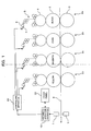
- FIG. 1 shows a general configuration of an offset rotary press for newspapers according to a first embodiment of the present invention.
- the offset rotary press for newspapers of the present embodiment is a double-sided printing press for multi-color printing and includes printing units 2a, 2b, 2c and 2d disposed for different ink colors [black (k), cyan (c), magenta (m) and yellow (y) ] along a transport path of a printing sheet 8.
- each of the printing units 2a, 2b, 2c and 2d includes an ink supplying apparatus of the ink key type which includes a plurality of ink keys 7 and an ink fountain roller 6.
- the ink supplying amount can be adjusted by the gap amount (the gap amount is hereinafter referred to as ink key opening) of each of the ink keys 7 from the ink fountain roller 6.
- the ink keys 7 are juxtaposed in the printing widthwise direction, and the ink supplying amount can be adjusted in a unit of the width of each of the ink keys 7 (the ink supplying unit width by each ink key 7 is hereinafter referred to as key zone).
- the ink whose supplying amount is adjusted by each ink key 7 is kneaded to a suitable degree to form a thin film in an ink roller group 5 and then supplied to a printing surface of a printing cylinder 4.
- each of the printing units 2a, 2b, 2c and 2d includes a pair of blanket cylinders 3, 3 disposed across the transport path of the printing sheet 8, and a printing cylinder 4 and an ink supplying apparatus are provided for each of the blanket cylinders 3.
- the offset rotary press for newspapers includes a pair of line sensor type IRGB densitometers 1 on the further downstream of the most downstream printing units 2d.
- Each of the line sensor type IRGB densitometers 1 is a measuring instrument for measuring a color of a picture on the printing sheet 8 as reflection densities (color mixture halftone densities) of I (infrared radiation), R (red), G (green) and B (blue) on a line in the printing widthwise direction.
- the offset rotary press for newspapers can measure the reflection density over the overall printing sheet 8 or measure the reflection density at an arbitrary position of the printing sheet 8.
- the line sensor type IRGB densitometers 1 are disposed on the opposite front and rear sides across the transport path of the printing sheet 8 so that they can measure the reflection density on the opposite front and rear faces of the printing sheet 8.
- the reflection densities measured by the line sensor type IRGB densitometers 1 are transmitted to an arithmetic operation apparatus 10.
- the arithmetic operation apparatus 10 is an apparatus for arithmetically operating control data of the ink supplying amount, and performs arithmetic operation based on the reflection densities measured by the line sensor type IRGB densitometers 1 to arithmetically operate the opening of each of the ink keys 7 for making the color of the picture of the printing sheet 8 coincide with a target color.
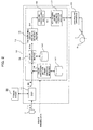
- FIG. 2 is a view showing a general configuration of a picture color tone controlling apparatus for the offset rotary press for newspapers according to the embodiment of the present invention and simultaneously is a functional block diagram showing the arithmetic operation apparatus 10 with attention paid to a color tone controlling function.
- the arithmetic operation apparatus 10 includes a DSP (digital signal processor) 11 and a PC (personal computer) 12 disposed separately from the printing press.
- the PC 12 has functions as a color conversion section 14, an ink supplying amount arithmetic operation section 15, an online controlling section 16 and a key opening limiter arithmetic operation section 17 allocated thereto.
- the line sensor type IRGB densitometers 1 are connected to the input side of the arithmetic operation apparatus 10, and a controlling apparatus 20 built in the printing press is connected to the output side of the arithmetic operation apparatus 10.
- the controlling apparatus 20 functions as ink supplying amount adjusting means for adjusting the ink supplying amount for each of the key zones of the ink keys 7.
- the controlling apparatus 20 controls an opening/closing apparatus not shown for opening and closing each of the ink keys 7 and can adjust the key opening independently for each ink key 7 of each of the printing units 2a, 2b, 2c and 2d.
- a touch panel 30 as a display apparatus is connected to the arithmetic operation apparatus 10.
- the touch panel 30 can be used to display a printing surface of the printing sheet 8 whose image is picked up by the line sensor type IRGB densitometer 1 and select an arbitrary region on the printing surface with a finger.
- FIG. 3 is a view illustrating a processing flow of color tone control by the arithmetic operation apparatus 10.
- the processing substance of color tone control by the arithmetic operation apparatus 10 is described principally with reference to FIG. 3.
- solid density values Di ( ⁇ ) of wavelengths ⁇ of I (infrared radiation), R (red), G (green), B (blue) are acquired from data obtained in advance by printing a color scale of the Japan Color (ISO12642) or the like in the standard density.
- a color scale of the Japan Color (ISO12642) or the like is printed in advance in the standard density using a printing press to be used, and the density is detected by the IRGB densitometer based on the printing result of the color scale. Consequently, the solid density value Di ( ⁇ ) of each color (each of monochromes and color mixtures of two, three or four colors) of the wavelength ⁇ can be acquired.
- the solid density values Di ( ⁇ ) can be utilized after the determination is performed once.
- plate making data are inputted in advance to the arithmetic operation apparatus 10, and the arithmetic operation apparatus 10 acquires k, c, m, y data of each pixel from the plate making data in advance.
- a noticed pixel region (hereinafter referred simply also as noticed point) is set first (step S02), and the process of the color tone control is performed based on the set noticed pixel region.
- bitmap data are converted into low-resolution data equivalent to CIP4 data according to the format of the printing press and then a process is performed in a unit of a pixel of a sensor described below.
- the region having a high autocorrelation for each ink color is a region in which the autocorrelation sensitivity H has a value higher than a predetermined value set in advance and is a region of a pixel unit of the sensor (IRGB densitometer) 1.
- the pixel unit of the sensor is a minimum unit of the resolution of the sensor (IRGB densitometer) 1.
- a pixel group formed by collecting a great number of pixels of the plate making data corresponds to one pixel (one block) of the sensor pixel unit.
- a region of 2 pixels in the vertical direction by 2 pixels in the horizontal direction is one pixel unit of the sensor pixel unit.
- Hc c P / (c + m + y + k)
- pixel area ratio data c, m, y, k.
- the value of the autocorrelation sensitivity H is arithmetically operated and individually compared with the reference autocorrelation sensitivity value (predetermined value) H 0 set in advance. It is to be noted that p is an exponentiation of the autocorrelation, and, for example, approximately 1.3 is selected as the value of the exponent value p.
- the reference autocorrelation sensitivity value H 0 can be set by inputting operation of the operator. Therefore, it is possible to set the reference autocorrelation sensitivity value H 0 to a rather high value to set the noticed pixel region restrictively to a region having a considerably high autocorrelation so that the density detection sensitivity is raised from a point which is of the pertaining ink and has a high tone thereby to raise the accuracy of the color tone control although the noticed pixel region decreases.
- the reference autocorrelation sensitivity value H 0 it is possible to set the reference autocorrelation sensitivity value H 0 to a rather low value to set the noticed pixel region including even a region in which the autocorrelation is not very high so that the noticed pixel region is expanded thereby to raise the accuracy of the color tone control although the density detection sensitivity drops.
- a recommendable value for example, an average autocorrelation value over the entire picture
- H 0 is inputted in advance, and an unskilled operator can utilize the recommendable value.
- the reference autocorrelation sensitivity value H 0 is commonly used for the different ink colors, also it is a possible idea to make the reference autocorrelation sensitivity value H 0 different among the different ink colors.
- a target color mixture halftone density is set for the set noticed pixel region of each ink (step S04).
- the arithmetic operation apparatus 10 has tone values (or line ratio) Ak, Ac, Am, Ay data of the noticed pixel regions acquired based on the plate making data.
- the color conversion section 14 of the PC 12 includes a database 141 for coordinating the tone values and color mixture halftone densities of the individual ink colors with each other.
- the database 141 is produced with reference to data [conversion table which defines a corresponding relationship among tone values (k, c, m, y), color mixture halftone densities (I, R, G, B), and color coordinate values (L, a, b) of the standard colors] obtained by printing a printed matter under the newspaper printing Japan Color (ISO12642) standard established by the ISO/TC130 national commission and actually measuring the printed pattern by an IRGB densitometer.
- the color conversion section 14 determines color mixture halftone densities corresponding to the inputted line ratios Ak, Ac, Am, Ay for each key zone and sets the determined color mixture halftone densities as target color mixture halftone densities Io, Ro, Go, Bo.
- the color conversion section 14 is configured such that it can variably adjust the dot gain for each degree of density of the halftone and can set the target color mixture halftone densities Io, Ro, Go, Bo with the dot gain taken into consideration using a parameter determined based on the dot gain used as a function as the parameter to be used when the line ratios Ak, Ac, Am, Ay are converted into the color mixture halftone densities Io, Ro, Go, Bo.
- step S10 the line sensor type IRGB densitometer 1 measures the reflected light amounts i' , r' , g' , b' of each of the pixels on the overall face of the overall printing sheet 8.
- the reflectedlight amounts i' , r' , g' , b' of the pixels measured by the IRGB densitometer 1 are inputted to the DSP 11.
- the DSP 11 performs, at step S20, moving averaging in a unit of a predetermined number of prints with regard to the reflected light amounts i' , r' , g' , b' of the pixels to arithmetically operate reflected light amounts i, r, g, b of the pixels from which noise components are removed. Then, at step S30, the reflected light amounts i, r, g, b are averaged for each key zone to arithmetically operate color mixture halftone densities (actual color mixture halftone densities) I, R, G, B with reference to a reflected light amount at a blank portion.
- color mixture halftone densities actual color mixture halftone densities
- the color mixture halftone densities I, R, G, B of each noticed pixel region arithmetically operated by the DSP 11 are inputted to the color conversion section 14 of the PC 12.
- the color conversion section 14 performs the processes at steps S40, S50 and S60.
- the target color mixture halftone densities Io, Ro, Go, Bo set at step S04 and the tone values of each ink color corresponding to the actual color mixture halftone densities I, R, G, B arithmetically operated at step S30 are arithmetically operated individually.
- the database 141 is used for the arithmetic operations, and the tone values of each ink color corresponding to the target color mixture halftone densities Io, Ro, Go, Bo are arithmetically operated as target tone values ko, co, mo, yo and the tone values of each ink color corresponding to the actual color mixture halftone densities I, R, G, B are arithmetically operated as actual tone values k, c, m, y.
- the database 141 not only the conversion table [hereinafter referred to sometimes as look-up table (LUT)] produced based on the printing result obtained by printing the color scale of the Japan Color (ISO12642) or the like under the standard density is inputted as described hereinabove. Meanwhile, also a publicly known expanded Neugebauer expression which is produced based on the printing result described above and wherein the Nielsen coefficient (coefficient of Yule-Nielsen) n is set to a value (for example, n ⁇ approximately 100) with which the relationship between the tone values and the color mixture halftone density value becomes substantial linear is inputted.
- LUT look-up table
- c, m, y, k, kc, km, ky, cm, cy, my, kcm, kcy, kmy, cmy and kcmy in the expression (A) indicate the halftone dot ratios of the colors (monochromes or color mixtures).
- kc indicates the product of the tone values of black (k) and cyan (c)
- kcmy indicates the product of black (k), cyan (c), magenta (m) and yellow (y).
- Dkc ( ⁇ ) , Dkm ( ⁇ ) , ..., Dkcmy ( ⁇ ) [solid density value Di ( ⁇ ) of the wavelength ⁇ of each color i] in the expression (A) individually indicate each a solid overlapping density value of the wavelength ⁇ in the target density value for each ink color.
- Dkc( ⁇ ) indicates a density value of the wavelength ⁇ in the overlapping target density value of each color in the color mixture between black (k) and cyan (c)
- Dkcmy ( ⁇ ) indicates a density value of the wavelength ⁇ in the overlapping target density value of each color in the color mixture among black (k), cyan (c), magenta (m), and yellow (y).
- ⁇ indicates the wavelength of I, R, G, or B.
- the Di( ⁇ ) values are determined in advance as described above.
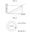
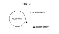
- the relationship between the tone values and the color mixture halftone density in a color space region assumed with respect to the reference density can be easily extended and applied to an outer side region of the color space as indicated by an alternate long and two dashes line in FIG. 5.
- the relationship between the tone values and the color mixture halftone density can be applied also to the outside space to the color space region indicated by a full line circle in FIG. 5, and the color space can be substantially extended as indicated by an alternate long and two dashes line circle in FIG. 5 while the relationship between the tone values and the color mixture halftone density is set with respect to the reference density.
- the color conversion section 14 arithmetically operates monochromatic halftone densities of the ink colors corresponding to the target tone values ko, co, mo, yo and the actual tone values k, c, m, y at step S50.
- a map as shown in FIG. 6 is used for the arithmetic operation.
- FIG. 6 shows an example of a map wherein the monochromatic halftone density measured where the tone values are varied is plotted as a characteristic curve, and the map is produced from data measured in advance. In the example shown in FIG.
- a target monochromatic halftone density Dako and an actual monochromatic halftone density Dak are determined from the characteristic curve in the map.
- the color conversion section 14 determines target monochromatic halftone densities Dako, Daco, Damo, Dayo and actual monochromatic halftone densities Dak, Dac, Dam, Day of the ink colors.
- the color conversion section 14 arithmetically operates solid density differences ⁇ Dsk, ⁇ Dsc, ⁇ Dsm, ⁇ Dsy of the ink colors corresponding to differences between the target monochromatic halftone densities Dako, Daco, Damo, Dayo and the actual monochromatic halftone densities Dak, Dac, Dam, Day.
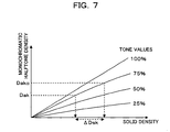
- the solid density depends also on the tone values, and, with regard to the monochromatic halftone density, the solid density decreases as the tone values increase. Therefore, the color conversion section 14 performs arithmetic operation using such a map as shown in FIG. 7.
- FIG. 7 FIG.
- the color conversion section 14 selects the characteristic curves corresponding to the target tone values ko, co, mo, yo of the ink colors from within the map shown in FIG. 7, and determines the solid density differences ⁇ Dsk, ⁇ Dsc, ⁇ Dsm, ⁇ Dsy by applying the target monochromatic halftone densities Dako, Daco, Damo, Dayo and the actual monochromatic halftone densities Dak, Dac, Dam, Day to the selected characteristic curves.
- the target monochromatic halftone densities Dako, Daco, Damo, Dayo the target monochromatic halftone densities Dak, Dac, Dam, Day
- the solid density difference ⁇ Dsk of black is determined from within the 75% characteristic curve in the map.
- the solid density differences ⁇ Dsk, ⁇ Dsc, ⁇ Dsm, ⁇ Dsy of the individual ink colors arithmetically operated by the color conversion section 14 are inputted to the ink supplying amount arithmetic operation section 15.
- the ink supplying amount arithmetic operation section 15 arithmetically operates key opening difference amounts ⁇ Kk, ⁇ Kc, ⁇ Km, ⁇ Ky corresponding to the solid density differences ⁇ Dsk, ⁇ Dsc, ⁇ Dsm, ⁇ Dsy, respectively.
- the key opening difference amounts ⁇ Kk, ⁇ Kc, ⁇ Km, ⁇ Ky are increasing or decreasing amounts from the key openings Kk0, Kc0, Km0, Ky0 at present (key openings Kk, Kc, Km, Ky outputted to the controlling apparatus 20 of the printing press by the process at step S100 in the preceding operation cycle) of the individual ink keys 7, and the ink supplying amount arithmetic operation section 15 performs the arithmetic operation using the known API function (auto-preset inking function).
- the API function is a function indicating a relationship between image area ratios A (Ak, Ac, Am, Ay) and the key openings K (Kk, Kc, Km, Ky) for each key zone to establish a reference density.
- the online controlling section 16 corrects the key opening difference amounts ⁇ Kk, ⁇ Kc, ⁇ Km, ⁇ Ky arithmetically operated by the color conversion section 14 taking the dead times from the printing units 2a, 2b, 2c and 2d to the line sensor type IRGB densitometer 1, reaction times of the ink keys 7 per unit time and the printing speed into consideration.
- a time delay after a key opening signal is inputted until a corresponding ink key 7 moves to change the key opening thereby to change the ink amount to be supplied to the printing sheet and the variation of the ink amount appears as a variation of the reflected light amount on the line sensor type IRGB densitometer 1 is taken into consideration.
- the online controlling section 16 adds the key openings Kk0, Kc0, Km0, Ky0 at present to the key opening difference amounts (online control key opening differences) ⁇ Kk, ⁇ Kc, ⁇ Km, ⁇ Ky to determine online control key openings Kkl, Kcl, Kml, Kyl and inputs the determined online control key openings Kkl, Kcl, Kml, Kyl to the key opening limiter arithmetic operation section 17.
- the key opening limiter arithmetic operation section 17 performs correction of restricting upper limit values to the online control key openings Kkl, Kcl, Kml, Kyl arithmetically operated by the online controlling section 16. This is a process for restricting the key openings from increasing abnormally particularly arising from an estimated error of the color conversion algorithm (processes at steps S40, S50 and S60) in a low image area ratio region. Then at step S90, the key opening limiter arithmetic operation section 17 transmits the key openings Kk, Kc, Km, Ky whose upper limit values are restricted as key opening signals to the controlling apparatus 20 of the printing press.
- the controlling apparatus 20 adjusts the ink keys 7 of the printing units 2a, 2b, 2c and 2d based on the key openings Kk, Kc, Km, Ky received from the arithmetic operation apparatus 10. Consequently, the ink supplying amounts of the ink colors are controlled so as to conform to a target color tone for each key zone.
- the color tone control can be carried out immediately after build up of the printing press as described hereinabove. Then, noticed pixel regions (noticed points) are individually set and the color mixture halftone density of the noticed points is set as the target color mixture halftone densities Io, Ro, Go, Bo, and the actual color mixture halftone densities I, R, G, B of the corresponding noticed points on a main printing sheet are measured and used for feedback control. Consequently, also where plate making data such as 1 bit-Tiff or CIP4 data are not available, the color tone control can be performed for the specific noticed points of the picture.
- the measurement error of the line sensor type IRGB densitometer 1 is small and the color tone control can be performed stably.
- the color tone control can be performed more stably where the line ratio of the picture in the key zone is low.
- a pixel having the highest density sensitivity is arithmetically operated and the arithmetically operated pixel is set as the noticed point.
- a second embodiment of the present invention is described.
- the publicly known Neugebauer expression (B) which is dot gain corrected is used in place of the conversion table in the embodiment described above.
- the solid density values Di ( ⁇ ) of the wavelengths ⁇ of the colors of the colors of I (Infrared radiation), R (Red), G (Green), B (Blue) are acquired from data obtained in advance by printing the color scale of the Japan Color (ISO12642) or the like under the standard density and for which dot gain correction is performed, and the publicly known Neugebauer expression (B) for which dot gain correction is defined in such a manner as given below and the expression (B) is used to determine the color mixture halftone density.
- the tone values data k, c, m, y in the expression (B) are dot gain corrected in the following manner.
- monochromatic halftone densities Dc50 to Dk50 when the tone values of the plate making data are 50% and monochromatic solid densities (monochromatic solid halftone densities) Dc100 to Dk100 when the tone values of the plate making data are solid (100%) are obtained by extraction from the color scale density value data.
- color dot gain amounts (values before correction) DGc' to DGk' when the monochromatic tone values of the platemaking data are 50% are calculated using the following expression (C) based on the values obtained as above.
- DGc to DGk color dot gain amount when the monochromatic tone values of the plate making data are 50%
- Dc50 to Dk50 monochromatic halftone density when the tone values of the plate making data are 50% (extracted from the color scale density value data)
- Dc100 to Dk100 monochromatic solid density when the tone values of the plate making data are solid (100%) (extracted from the color scale density value data).
- corrected tone values data k, c, m, y can be obtained.
- the target density can be changed. For example, where the dot gain increases because of degradation of a blanket or the like of the printing press, if the dot gain correction coefficient is increased from 1, then the target value can be calculated with accuracy.
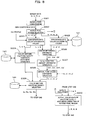
- a third embodiment of the present invention is described with reference to FIG. 8.
- the present embodiment is characterized in the settingmethod of the target density (target color mixture halftone density) of a noticed pixel region (noticed point).
- a flow chart shown in FIG. 8 illustrates the substance of processing (substance of a process corresponding to that at step S04 in FIG. 3) in the present embodiment in detail. Since the substance of the other processes for picture color tone control is such as described hereinabove with reference to FIG. 3, description of the substance is omitted here.
- bitmap data are converted into low-resolution data corresponding to CIP4 data according to the format of the printing press, and at step S322, a noticed point corresponding to each ink color is set for each ink supplying unit width. Since the substance of the processes at steps S321 and S322 is similar to that at steps S311 and S312 according to the second embodiment, detailed description thereof is omitted.
- the ICC profile received from the base station of the newspaper company is used to convert the tone values ki, ci, mi, yi of the noticed points into a color coordinate value L, a, b.
- a conversion table stored in the database 141 is used to convert the color coordinate value L, a, b determined at step S324 into a color mixture halftone density.
- the color mixture halftone density is four-dimensional information while the color coordinate value is three-dimensional information, the color mixture halftone density corresponding to the color coordinate value is not determined uniquely. In order to determine the color mixture halftone density uniquely, some additional information is required. However, from the ICC profile, only three-dimensional information of the color coordinate value can be obtained.
- the tone values data of the printing picture that is, the tone values ki, ci, mi, yi corresponding to the color coordinate value L, a, b, are utilized to select, in development from such three-dimensional information into four-dimensional information, the most appropriate pieces of four-dimensional information from among a large number of pieces of the four-dimensional information which are regarded as candidates.
- the conversion table stored in the database 141 is used to convert the tone values ki, ci, mi, yi of the noticed points into color coordinate values L', a', b'.
- color differences ⁇ L' , ⁇ a', ⁇ b' between the color coordinate values L, a, b determined at step S323 and the color coordinate values L', a', b' determined at step S325 are arithmetically operated.
- variation amounts ⁇ k' , ⁇ c', ⁇ m', ⁇ y' of the tone values corresponding to the color differences ⁇ L', ⁇ a', ⁇ b', respectively, are arithmetically operated.
- the variation amounts of the tone values can be approximated by the following expressions using the variation amounts of the color coordinate values. It is to be noted that a and b in the following expressions are linear approximation coefficients.
- the variation amounts ⁇ k', ⁇ c' , ⁇ m' , ⁇ y' determined at step S327 are added to the tone values ki, ci, mi, yi of the noticed points, and the resulting values are set as virtual tone values k', c', m', ⁇
- the virtual tone values k', c', m', y' are applied to the conversion table recorded in the database 141 to select, from among the color mixture halftone density candidates determined at step S324, those which correspond most to the virtual tone values k', c', m' , y' .
- the selected color mixture halftone densities are set as the target color mixture halftone densities Io, Ro, Go, Bo and are used in the processes at steps beginning with step S40 together with the actual color mixture halftone densities I, R, G, B of the noticed points arithmetically operated at step S330.
- the color tone can be adjusted accurately and easily to a color tone desired by the printing requesting source or the like when compared with alternative color adjustment which is performed through comparison with a proof-sheet as is performed conventionally. Accordingly, with the present method, the appearing amount of paper loss before an OK sheet is obtained can be reduced significantly.
- the embodiments of the present invention are not limited to those described above.
- a spot type IRGB densitometer may be used to scan a printing sheet two-dimensionally.
- the present invention also when printing is performed with a density exceeding an estimated maximum density (reference density), it is possible to expand the color space and use an IRGB densitometer to perform color tone control, and it is possible to cope with various demands for the printing color tone . Further, since an IRGB densitometer is used, the present invention can be applied also to picture color tone control in such high speed printing as in the case of, for example, a rotary press for newspapers and can be applied to various printing application.
Landscapes
- Physics & Mathematics (AREA)
- Engineering & Computer Science (AREA)
- General Physics & Mathematics (AREA)
- Immunology (AREA)
- Chemical & Material Sciences (AREA)
- Analytical Chemistry (AREA)
- Biochemistry (AREA)
- General Health & Medical Sciences (AREA)
- Health & Medical Sciences (AREA)
- Life Sciences & Earth Sciences (AREA)
- Pathology (AREA)
- Spectroscopy & Molecular Physics (AREA)
- Multimedia (AREA)
- Signal Processing (AREA)
- Quality & Reliability (AREA)
- Facsimile Image Signal Circuits (AREA)
- Inking, Control Or Cleaning Of Printing Machines (AREA)
- Color Image Communication Systems (AREA)
Applications Claiming Priority (2)
| Application Number | Priority Date | Filing Date | Title |
|---|---|---|---|
| JP2004336507 | 2004-11-19 | ||
| PCT/JP2005/020848 WO2006054521A1 (fr) | 2004-11-19 | 2005-11-14 | Procédé de contrôle de ton de couleur de motif et contrôleur |
Publications (2)
| Publication Number | Publication Date |
|---|---|
| EP1815985A1 true EP1815985A1 (fr) | 2007-08-08 |
| EP1815985A4 EP1815985A4 (fr) | 2011-01-05 |
Family
ID=36407064
Family Applications (1)
| Application Number | Title | Priority Date | Filing Date |
|---|---|---|---|
| EP05806335A Withdrawn EP1815985A4 (fr) | 2004-11-19 | 2005-11-14 | Procédé de contrôle de ton de couleur de motif et contrôleur |
Country Status (4)
| Country | Link |
|---|---|
| US (1) | US7755797B2 (fr) |
| EP (1) | EP1815985A4 (fr) |
| JP (1) | JPWO2006054521A1 (fr) |
| WO (1) | WO2006054521A1 (fr) |
Families Citing this family (12)
| Publication number | Priority date | Publication date | Assignee | Title |
|---|---|---|---|---|
| DE102005024473B4 (de) * | 2005-05-24 | 2008-08-28 | Hiflex Software Gmbh | Verfahren zur Übermittlung eines Farbauszugs und Management Information System |
| JP2009178883A (ja) * | 2008-01-30 | 2009-08-13 | Ryobi Ltd | カラー印刷機の印刷画像品質管理方法及び印刷画像品質管理装置 |
| DE102009046853A1 (de) * | 2009-11-19 | 2011-05-26 | Manroland Ag | Verfahren zur Bestimmung von Eigenschaften eines bedruckten Bedruckstoffs |
| JP5782785B2 (ja) * | 2010-05-12 | 2015-09-24 | 凸版印刷株式会社 | 色予測装置、色予測方法、プログラム、テーブル作成装置、および、印刷システム |
| US8763528B2 (en) * | 2010-12-09 | 2014-07-01 | Goss International Americas, Inc. | Closed loop color control of selected regions using solid color regions within images |
| EP2836903A1 (fr) | 2012-04-12 | 2015-02-18 | Hewlett-Packard Indigo B.V. | Impression avec données de couleur de référence |
| JP6287294B2 (ja) * | 2013-03-15 | 2018-03-07 | 株式会社リコー | 画像検査装置、画像検査システム及び画像検査方法 |
| BR112016021716B1 (pt) * | 2014-03-21 | 2022-02-15 | Bobst Firenze S.R.L. | Dispositivo para detectar e ajustar os parâmetros de impressão continuamente em uma máquina de impressão flexográfica e método para detectar e ajustar a densidade de impressão e os parâmetros colorimétricos em uma máquina de impressão flexográfica |
| US9773324B1 (en) * | 2016-03-23 | 2017-09-26 | Disney Enterprises, Inc. | Systems and methods for identifying targets on a display |
| JP6922446B2 (ja) * | 2017-06-06 | 2021-08-18 | セイコーエプソン株式会社 | プロファイル調整方法 |
| US10979600B2 (en) * | 2017-09-05 | 2021-04-13 | Hp Indigo B.V. | Method and printer system for determining adjusted output settings |
| CN117074247A (zh) * | 2023-10-12 | 2023-11-17 | 杭州宏华数码科技股份有限公司 | 用于确定待测墨水的墨水密度方法、设备和介质 |
Family Cites Families (11)
| Publication number | Priority date | Publication date | Assignee | Title |
|---|---|---|---|---|
| US5357448A (en) * | 1993-02-02 | 1994-10-18 | Quad/Tech, Inc. | Method and apparatus for controlling the printing of an image having a plurality of printed colors |
| DE4431270C2 (de) * | 1993-10-21 | 1997-01-16 | Roland Man Druckmasch | Verfahren zur Steuerung der Farbführung einer autotypisch arbeitenden Druckmaschine |
| JP3384769B2 (ja) * | 1999-04-19 | 2003-03-10 | リョービ株式会社 | インキ供給量調整装置およびインキ供給量調整方法 |
| JP2001018364A (ja) | 1999-07-12 | 2001-01-23 | Toppan Printing Co Ltd | 絵柄色調監視装置および印刷色調制御装置 |
| JP2001047605A (ja) | 1999-08-13 | 2001-02-20 | Toppan Printing Co Ltd | 印刷色調管理装置 |
| JP3676177B2 (ja) | 2000-03-29 | 2005-07-27 | 三菱重工業株式会社 | 印刷機における色調制御方法及び装置 |
| JP3943873B2 (ja) * | 2001-07-26 | 2007-07-11 | 大日本スクリーン製造株式会社 | 印刷機におけるインキおよび水の供給量制御装置、ならびにそれを備えた印刷システム |
| US6698860B2 (en) | 2001-11-01 | 2004-03-02 | E. I. Du Pont De Nemours And Company | Spectral color reproduction with six color output |
| JP3848877B2 (ja) * | 2001-12-27 | 2006-11-22 | 三菱重工業株式会社 | 印刷機における色調制御方法とその装置 |
| JP3825427B2 (ja) * | 2002-08-26 | 2006-09-27 | 三菱重工業株式会社 | 印刷機の絵柄色調制御方法および印刷機 |
| JP4293044B2 (ja) * | 2004-04-21 | 2009-07-08 | ブラザー工業株式会社 | 画像形成装置、画像形成方法及び画像形成プログラム |
-
2005
- 2005-11-14 WO PCT/JP2005/020848 patent/WO2006054521A1/fr not_active Ceased
- 2005-11-14 EP EP05806335A patent/EP1815985A4/fr not_active Withdrawn
- 2005-11-14 JP JP2006545014A patent/JPWO2006054521A1/ja active Pending
- 2005-11-14 US US11/666,683 patent/US7755797B2/en not_active Expired - Fee Related
Also Published As
| Publication number | Publication date |
|---|---|
| US20080216695A1 (en) | 2008-09-11 |
| US7755797B2 (en) | 2010-07-13 |
| WO2006054521A1 (fr) | 2006-05-26 |
| JPWO2006054521A1 (ja) | 2008-05-29 |
| EP1815985A4 (fr) | 2011-01-05 |
Similar Documents
| Publication | Publication Date | Title |
|---|---|---|
| EP1983738A1 (fr) | Methode et dispositif de verification avant impression de teinte d'image a imprimer, methode de realisation de plaque et methode et dispositif de commande de teinte d'image | |
| US20100002246A1 (en) | Printing simulation method and apparatus, picture color tone controlling method and apparatus for printing press, and printing press | |
| JP3825427B2 (ja) | 印刷機の絵柄色調制御方法および印刷機 | |
| EP1977899A1 (fr) | Regulateur de tonalite d'image pour imprimante et procede de regulation de la tonalite d'image | |
| US7755797B2 (en) | Picture color tone controlling method and apparatus | |
| US7755798B2 (en) | Picture color tone controlling method and apparatus | |
| EP1634704B1 (fr) | Dispositif et procédé de contrôle d'une image imprimée en couleurs. | |
| US20060050320A1 (en) | Picture color tone controlling method and apparatus | |
| JP2006076191A5 (fr) | ||
| JP4801700B2 (ja) | 印刷機の絵柄色調の印刷前確認方法及び装置 | |
| JP2006068948A5 (fr) | ||
| US7573613B2 (en) | Method and apparatus for controlling picture color tone of printing press | |
| JP4691116B2 (ja) | 印刷機の印刷前の色調確認方法及び装置並びに製版方法 | |
| JP2006239955A5 (fr) | ||
| JP2006239955A (ja) | 印刷機の目標混色網濃度設定方法及び装置並びに印刷機の絵柄色調制御方法及び装置 | |
| JP5184295B2 (ja) | 印刷機の目標混色網濃度設定方法及び装置並びに印刷機の絵柄色調制御方法及び装置 | |
| JP3836107B2 (ja) | 印刷機の絵柄色調制御方法および装置 | |
| JP2006159904A (ja) | 絵柄色調制御方法及び装置 |
Legal Events
| Date | Code | Title | Description |
|---|---|---|---|
| PUAI | Public reference made under article 153(3) epc to a published international application that has entered the european phase |
Free format text: ORIGINAL CODE: 0009012 |
|
| 17P | Request for examination filed |
Effective date: 20070601 |
|
| AK | Designated contracting states |
Kind code of ref document: A1 Designated state(s): DE FR GB |
|
| DAX | Request for extension of the european patent (deleted) | ||
| RBV | Designated contracting states (corrected) |
Designated state(s): DE FR GB |
|
| RAP1 | Party data changed (applicant data changed or rights of an application transferred) |
Owner name: MITSUBISHI HEAVY INDUSTRIES PRINTING & PACKING MAC |
|
| RAP1 | Party data changed (applicant data changed or rights of an application transferred) |
Owner name: MITSUBISHI HEAVY INDUSTRIES PRINTING & PACKAGING M |
|
| STAA | Information on the status of an ep patent application or granted ep patent |
Free format text: STATUS: THE APPLICATION HAS BEEN WITHDRAWN |
|
| A4 | Supplementary search report drawn up and despatched |
Effective date: 20101203 |
|
| 18W | Application withdrawn |
Effective date: 20101221 |