EP1816009A1 - Mécanisme de fermeture pour feuilles mobiles perforées - Google Patents
Mécanisme de fermeture pour feuilles mobiles perforées Download PDFInfo
- Publication number
- EP1816009A1 EP1816009A1 EP06101378A EP06101378A EP1816009A1 EP 1816009 A1 EP1816009 A1 EP 1816009A1 EP 06101378 A EP06101378 A EP 06101378A EP 06101378 A EP06101378 A EP 06101378A EP 1816009 A1 EP1816009 A1 EP 1816009A1
- Authority
- EP
- European Patent Office
- Prior art keywords
- mandrels
- curved
- mandrel
- closure mechanism
- mechanism according
- Prior art date
- Legal status (The legal status is an assumption and is not a legal conclusion. Google has not performed a legal analysis and makes no representation as to the accuracy of the status listed.)
- Granted
Links
- 230000007246 mechanism Effects 0.000 title claims abstract description 44
- 238000010409 ironing Methods 0.000 claims description 31
- 238000005452 bending Methods 0.000 claims description 14
- 230000003014 reinforcing effect Effects 0.000 description 5
- XEEYBQQBJWHFJM-UHFFFAOYSA-N Iron Chemical compound [Fe] XEEYBQQBJWHFJM-UHFFFAOYSA-N 0.000 description 2
- 230000006835 compression Effects 0.000 description 2
- 238000007906 compression Methods 0.000 description 2
- 238000004080 punching Methods 0.000 description 2
- 206010053648 Vascular occlusion Diseases 0.000 description 1
- 230000000694 effects Effects 0.000 description 1
- 229910052742 iron Inorganic materials 0.000 description 1
- 210000004373 mandible Anatomy 0.000 description 1
Images

Classifications
-
- B—PERFORMING OPERATIONS; TRANSPORTING
- B42—BOOKBINDING; ALBUMS; FILES; SPECIAL PRINTED MATTER
- B42F—SHEETS TEMPORARILY ATTACHED TOGETHER; FILING APPLIANCES; FILE CARDS; INDEXING
- B42F13/00—Filing appliances with means for engaging perforations or slots
- B42F13/16—Filing appliances with means for engaging perforations or slots with claws or rings
- B42F13/20—Filing appliances with means for engaging perforations or slots with claws or rings pivotable about an axis or axes parallel to binding edges
- B42F13/22—Filing appliances with means for engaging perforations or slots with claws or rings pivotable about an axis or axes parallel to binding edges in two sections engaging each other when closed
- B42F13/24—Filing appliances with means for engaging perforations or slots with claws or rings pivotable about an axis or axes parallel to binding edges in two sections engaging each other when closed wherein one section is in the form of fixed rods
Definitions
- the present invention relates to a closure mechanism for a perforated sheet holding device according to the preamble of claim 1.
- Locking mechanisms of this type usually provide two movably held mandrels, which can be brought into abutment or in a clearance position by means of a pivoting movement with two mandrels fastened to a baseplate.
- the two movably held mandrels can be fastened to a bracket strip, for example, which is held pivotably on the base plate about a pivot axis, but they can also be produced in one piece with the aid of a coil wire.
- the opening and closing of the closure mechanism takes place for example via a rocker arm or by direct tearing or compression of the ring yoke sections.
- the meeting of the end sections of the mutually associated mandrels causes the closing force of the respective pairs of mandrels to be different.
- the end portions of the mutually associated pairs of mandrels are usually shaped in their end surfaces so that the meeting of the end portions causes a mutual axial alignment of the mandrel pair, which in turn requires a minimum closing force.
- a time earlier meeting of a pair of mandrels but stops the further movement of the other mandrel pairs, so that this minimum closing force is sometimes no longer given and no axial alignment of the other pairs of mandrels in their closed position is given more.
- Incorrect axial alignment of mandrel pairs in their closed position is very troublesome when transferring sheets from the straight, stationary spikes to the curved mandrels, ie when turning over.
- Particularly disadvantageous may be different closing forces in closure mechanisms which are biased only in the direction of their open position, and in which the end portions of at least two pairs of mandrels are provided with closures which fix the mandrels in their closed position.
- locking mechanisms of this type can be dispensed with lever. Instead, closing is accomplished by compressing a pair of associated mandrels and opening by compressing the juxtaposed, movable and shuttered mandrels by means of a finger force acting transversely to the longitudinal axis of the mandrels. The elastic deflection of the movable mandrels in the course of opening the closure is released, and the shutter mechanism opens due to the bias of the movable mandrels toward its open position.
- Claim 1 relates to closure mechanisms for a holding device for perforated, loose leaves with a base plate on which immovable mandrels are fixed and curved mandrels are movably arranged, wherein the curved mandrels from an open position in which the end portions of the curved mandrels of the End portions of the stationary mandrels are spaced, in a closed position, in which abut the end portions of the curved mandrels against the end portions of the stationary mandrels, are pivotable, and are biased at least in the direction of its open position.
- the greater spacing of the at least one curved mandrel can be ensured by an inelastic bending of this curved mandrel.
- the curved mandrels according to claim 3 are arranged on an ironing strip, the larger spacing of the at least one curved mandrel can alternatively also be ensured by an inelastic bending of the ironing strip.
- Claims 7 to 11 relate to an embodiment of a closure mechanism in which the feature according to the invention is particularly advantageous.
- the curved mandrels are biased in a direction transverse to their longitudinal axis, which indeed improves the closure, but causes higher closing forces when the end portions of the mandrels meet.
- the inventive feature due to which different closing forces different mandrel pairs can be avoided, particularly advantageous.
- Claims 9 and 10 describe such a closure in more detail.
- the closure is a toothing, wherein at least one of the arranged on at least one end portion of a mandrel tooth has an undercut, in which engages the respective other, arranged at the end portion of the opposing mandrel tooth.
- both the end portions of both curved mandrels and the end portions of both immovable mandrels have an undercut, which each interlock in the closed position.
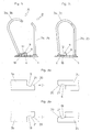
- FIG. 1 shows a side view of a closure mechanism in which the curved mandrels 3a, 3b and the ironing bar 4 are in their open position.
- the strap bar 4 is pivotally held on a base plate 1, as will be explained in more detail.
- the curved mandrels 3a, 3b may be formed on the ironing bar 4, but will usually riveted or attached to her.
- the immovable pins 2a, 2b are fixed, which will also be riveted in the rule.
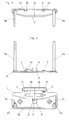
- the ironing bar 4 is explained in more detail with reference to FIG. 4. It can be seen here that the ironing bar 4 is preferably provided with a reinforcing rib 12 in order to give it greater stability.
- the reinforcing rib 12 is designed as a raised surface section.
- the strap strip 4 further has along its thorns 3a, 3b facing away from, longer side edge at least one mounting tabs 10 which projects laterally from the strap bar 4.
- the ironing bar 4 further has at least one opening 13, the function of which will be explained below.
- the base plate 1 is explained in more detail with reference to FIG. 5.
- the base plate 1 also reinforcing ribs 14 and 16 in order to give greater stability.
- the reinforcing ribs 14 and 16 are designed as raised surface sections.
- the reinforcing rib 14 preferably extends over most of the base plate 1, but at least the area of the bores 15 for receiving fasteners, such as rivets, holds for fastening the shutter mechanism in a folder free.
- at least one tab 7 is punched out and bent up from the base plate 1, the function of which is also even closer in the following will be explained. By punching and bending of the tabs 7 arise in the base plate 1 openings 17.
- From the base plate 1 is also still a retaining tabs 8 punched out and bent, which has a bent toward the base plate 1 end portion 9. By punching and bending of the retaining tab 8 results in the base plate 1, the opening 11. From the base plate 1 is further a spring tab 18 punched out and bent.
- the mounting tabs 10 of the ironing bar 4 are inserted into the openings 17 of the base plate 1 and the tabs 7 of the base plate 1 inserted into the openings 13 of the ironing bar 4, whereby they define a pivot axis.
- the tabs 7 are so far bent when inserting the ironing bar 4 in the base plate 1 until the immovable spines 2 a, 2 b facing side edge of the ironing bar 4 can be pushed under the curved towards the base plate 1 end portion 9 of the retaining tab 8.
- the spring tab 18 rests against the underside of the ironing bar 4 and ensures a bias of the ironing bar 4 and thus the movable mandrels 3a, 3b against their open position.
- the ironing bar 4 is thus mounted on the base plate 1 and is in its open position, as can be seen in Fig. 1.
- This closure is designed in the illustrated embodiment as a toothing, which is explained with reference to FIGS. 3a and 3b.
- Fig. 3a shows the end portion of the right-hand curved mandrel 3a in relation to Fig. 4 in a direction along the direction A (Fig. 1).
- the right part of FIG. 3a shows the end portion of the stationary mandrel 2a, which is right in relation to FIG. 5, in a view along the direction B (FIG. 1).
- the end portion of the curved mandrel 3a in this case has an undercut 5 and the end portion of the immovable mandrel 2a an undercut 6.
- FIG. 3b shows the left part of FIG. 3b left in FIG. 4 in a view along the direction A (FIG. 1).
- the right part of Fig. 3b shows the end portion of the stationary mandrel 2b in Fig. 5 in a view along the direction B (Fig. 1).
- the end portion of the curved mandrel 3b in this case has an undercut 18 and the end portion of the stationary mandrel 2b an undercut 19.
- the curved mandrels 3a, 3b not to arrange perpendicular to the ironing bar 4, but to provide a slight inclination to the outside, so that due to this bias transverse to the longitudinal axis of the mandrels 3a, 3b in the closed position, the curved mandrels 3a, 3b are pressed into the undercuts 6, 19 ,
- the shutter mechanism To open the shutter mechanism, it is only necessary to press the curved mandrels 3a, 3b respectively inward, so that the respective tooth 21 from the respective undercut 6, 19 slides. Even if the curved mandrels 3a, 3b are firmly riveted to the ironing bar 4, yet they have sufficient ability to vibrate to bend by slight finger pressure, the curved mandrels 3a, 3b inwards. Furthermore, the ironing bar 4 may be provided with a corresponding elasticity. Due to the restoring spring force of the spring tab 18, the curved mandrels 3a, 3b are subsequently brought into the open position.
- mandrel pair 2b, 3b which is actuated by fingers, earlier than the second mandrel pair 2a, 3a, which is mitbetätigt with the actuated mandrel pair 2b, 3b closes.
- the time-shifted coincidence of the end portions of the associated mandrels 2a, 3a and 2b, 3b causes subsequently that the closing force of the respective mandrel pairs 2a, 3a and 2b, 3b is different.
- the closures provided at the end sections require a minimum closing force.
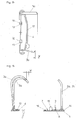
- This difference in the movement path W corresponds approximately to that bending of the mandrels 2b, 3b, which occurs due to the finger pressure when closing the mechanism.
- the end portions of the mandrels 2a, 3a and the mandrels 2b, 3b thus reach the same closing force at the same time in contact.
- the bending of the mandrel 3b relative to the mandrel 3a can also be seen in FIG. 7, where the longer path of movement W has been drawn from another perspective.
- the greater spacing of the curved mandrel 3b is ensured by an inelastic bending of this curved mandrel 3b.
- the greater spacing of the curved mandrel 3b may also be due to an inelastic bend the ironing bar 4 be ensured.
Landscapes
- Spinning Or Twisting Of Yarns (AREA)
- Paper (AREA)
- Greenhouses (AREA)
- Clamps And Clips (AREA)
- Bending Of Plates, Rods, And Pipes (AREA)
Priority Applications (3)
| Application Number | Priority Date | Filing Date | Title |
|---|---|---|---|
| DE502006009386T DE502006009386D1 (de) | 2006-02-07 | 2006-02-07 | Verschlussmechanik für gelochte, lose Blätter |
| AT06101378T ATE507088T1 (de) | 2006-02-07 | 2006-02-07 | Verschlussmechanik für gelochte, lose blätter |
| EP06101378A EP1816009B1 (fr) | 2006-02-07 | 2006-02-07 | Mécanisme de fermeture pour feuilles mobiles perforées |
Applications Claiming Priority (1)
| Application Number | Priority Date | Filing Date | Title |
|---|---|---|---|
| EP06101378A EP1816009B1 (fr) | 2006-02-07 | 2006-02-07 | Mécanisme de fermeture pour feuilles mobiles perforées |
Publications (2)
| Publication Number | Publication Date |
|---|---|
| EP1816009A1 true EP1816009A1 (fr) | 2007-08-08 |
| EP1816009B1 EP1816009B1 (fr) | 2011-04-27 |
Family
ID=36609492
Family Applications (1)
| Application Number | Title | Priority Date | Filing Date |
|---|---|---|---|
| EP06101378A Expired - Lifetime EP1816009B1 (fr) | 2006-02-07 | 2006-02-07 | Mécanisme de fermeture pour feuilles mobiles perforées |
Country Status (3)
| Country | Link |
|---|---|
| EP (1) | EP1816009B1 (fr) |
| AT (1) | ATE507088T1 (fr) |
| DE (1) | DE502006009386D1 (fr) |
Cited By (1)
| Publication number | Priority date | Publication date | Assignee | Title |
|---|---|---|---|---|
| WO2013156199A1 (fr) | 2012-04-16 | 2013-10-24 | Strategisch Initiatief Materialen Vzw Departement Flamac | Système à déflecteurs et système mélangeur magnétique comprenant un tel système à déflecteurs |
Citations (6)
| Publication number | Priority date | Publication date | Assignee | Title |
|---|---|---|---|---|
| DE378692C (de) * | 1923-07-26 | Killisch & Co | Briefordner o. dgl. mit geteilten Aufreihbuegeln, deren verstellbare Buegelteile starr miteinander verbunden sind | |
| DE1259292B (de) * | 1962-09-06 | 1968-01-25 | Soennecken Fa F | Ringmechanik fuer Sammelmappen, Ringbuecher od. dgl. |
| EP0207059A1 (fr) | 1985-06-03 | 1986-12-30 | Hans J. Horn | Dispositif de fermeture pour classeur |
| EP0911180A1 (fr) * | 1997-10-24 | 1999-04-28 | KOLOMAN HANDLER GESELLSCHAFT m.b.H. | Mécanisme d'enfilage |
| EP1129865A2 (fr) | 2000-03-01 | 2001-09-05 | Leco Stationery Manufacturing Co. Ltd. | Mécanisme de verrouillage pour classeur à levier |
| WO2002058942A1 (fr) * | 2001-01-26 | 2002-08-01 | Thomas Barth | Systeme de classement |
-
2006
- 2006-02-07 EP EP06101378A patent/EP1816009B1/fr not_active Expired - Lifetime
- 2006-02-07 DE DE502006009386T patent/DE502006009386D1/de not_active Expired - Lifetime
- 2006-02-07 AT AT06101378T patent/ATE507088T1/de active
Patent Citations (6)
| Publication number | Priority date | Publication date | Assignee | Title |
|---|---|---|---|---|
| DE378692C (de) * | 1923-07-26 | Killisch & Co | Briefordner o. dgl. mit geteilten Aufreihbuegeln, deren verstellbare Buegelteile starr miteinander verbunden sind | |
| DE1259292B (de) * | 1962-09-06 | 1968-01-25 | Soennecken Fa F | Ringmechanik fuer Sammelmappen, Ringbuecher od. dgl. |
| EP0207059A1 (fr) | 1985-06-03 | 1986-12-30 | Hans J. Horn | Dispositif de fermeture pour classeur |
| EP0911180A1 (fr) * | 1997-10-24 | 1999-04-28 | KOLOMAN HANDLER GESELLSCHAFT m.b.H. | Mécanisme d'enfilage |
| EP1129865A2 (fr) | 2000-03-01 | 2001-09-05 | Leco Stationery Manufacturing Co. Ltd. | Mécanisme de verrouillage pour classeur à levier |
| WO2002058942A1 (fr) * | 2001-01-26 | 2002-08-01 | Thomas Barth | Systeme de classement |
Cited By (1)
| Publication number | Priority date | Publication date | Assignee | Title |
|---|---|---|---|---|
| WO2013156199A1 (fr) | 2012-04-16 | 2013-10-24 | Strategisch Initiatief Materialen Vzw Departement Flamac | Système à déflecteurs et système mélangeur magnétique comprenant un tel système à déflecteurs |
Also Published As
| Publication number | Publication date |
|---|---|
| DE502006009386D1 (de) | 2011-06-09 |
| ATE507088T1 (de) | 2011-05-15 |
| EP1816009B1 (fr) | 2011-04-27 |
Similar Documents
| Publication | Publication Date | Title |
|---|---|---|
| EP1189764A1 (fr) | Mecanisme de classeur a anneaux | |
| EP2379340B1 (fr) | Mécanisme pour classeur | |
| EP1585156B1 (fr) | Dispositif de commutation électrique | |
| EP1834544A1 (fr) | Verrouillage pour tables de ping-pong dotée de demi-panneaux pivotants | |
| EP0207059B1 (fr) | Dispositif de fermeture pour classeur | |
| EP1914780B1 (fr) | Disjoncteur-sectionneur à fusibles et dispositif de verrouillage pour un disjoncteur-sectionneur à fusibles | |
| DE2653106C2 (de) | Klappenhalter | |
| EP0442845A1 (fr) | Mécanisme de fermeture pour classeur | |
| EP1816009B1 (fr) | Mécanisme de fermeture pour feuilles mobiles perforées | |
| AT502212B1 (de) | Verschlussmechanik für gelochte, lose blätter | |
| EP1682357A1 (fr) | Mecanisme de classeur | |
| AT500933B1 (de) | Verschlussmechanik für gelochte, lose blätter | |
| EP0520188B1 (fr) | Mécanisme pour classeur | |
| DE3004830A1 (de) | Haltevorrichtung fuer einen ringordner | |
| AT398293B (de) | Ordnermechanik für ordner für gelochte blätter | |
| EP0285599B1 (fr) | Elément de fermeture | |
| EP4094634B1 (fr) | Ferrure pliante permettant de relier de manière pivotante deux parties de meuble | |
| WO2002058942A1 (fr) | Systeme de classement | |
| EP0523351B1 (fr) | Mécanique pour classeur | |
| DE102006057321A1 (de) | Auf eine Tragschiene aufsetzbares Gerät | |
| DE102011018635A1 (de) | Ordnermechanik | |
| EP4379961A1 (fr) | Borne de connexion pour connecter un conducteur électrique | |
| DE102022131750A1 (de) | Anschlussklemme zum Anschließen einer elektrischen Leitung | |
| DE102022131747A1 (de) | Anschlussklemme zum Anschließen einer elektrischen Leitung | |
| DE102021113881A1 (de) | Klappbeschlag zur schwenkbaren Verbindung zweier Möbelteile |
Legal Events
| Date | Code | Title | Description |
|---|---|---|---|
| PUAI | Public reference made under article 153(3) epc to a published international application that has entered the european phase |
Free format text: ORIGINAL CODE: 0009012 |
|
| AK | Designated contracting states |
Kind code of ref document: A1 Designated state(s): AT BE BG CH CY CZ DE DK EE ES FI FR GB GR HU IE IS IT LI LT LU LV MC NL PL PT RO SE SI SK TR |
|
| AX | Request for extension of the european patent |
Extension state: AL BA HR MK YU |
|
| 17P | Request for examination filed |
Effective date: 20080201 |
|
| 17Q | First examination report despatched |
Effective date: 20080319 |
|
| AKX | Designation fees paid |
Designated state(s): AT BE BG CH CY CZ DE DK EE ES FI FR GB GR HU IE IS IT LI LT LU LV MC NL PL PT RO SE SI SK TR |
|
| GRAP | Despatch of communication of intention to grant a patent |
Free format text: ORIGINAL CODE: EPIDOSNIGR1 |
|
| GRAS | Grant fee paid |
Free format text: ORIGINAL CODE: EPIDOSNIGR3 |
|
| GRAA | (expected) grant |
Free format text: ORIGINAL CODE: 0009210 |
|
| AK | Designated contracting states |
Kind code of ref document: B1 Designated state(s): AT BE BG CH CY CZ DE DK EE ES FI FR GB GR HU IE IS IT LI LT LU LV MC NL PL PT RO SE SI SK TR |
|
| REG | Reference to a national code |
Ref country code: GB Ref legal event code: FG4D Free format text: NOT ENGLISH |
|
| REG | Reference to a national code |
Ref country code: CH Ref legal event code: EP |
|
| REG | Reference to a national code |
Ref country code: IE Ref legal event code: FG4D Free format text: LANGUAGE OF EP DOCUMENT: GERMAN |
|
| REF | Corresponds to: |
Ref document number: 502006009386 Country of ref document: DE Date of ref document: 20110609 Kind code of ref document: P |
|
| REG | Reference to a national code |
Ref country code: DE Ref legal event code: R096 Ref document number: 502006009386 Country of ref document: DE Effective date: 20110609 |
|
| REG | Reference to a national code |
Ref country code: NL Ref legal event code: VDEP Effective date: 20110427 |
|
| LTIE | Lt: invalidation of european patent or patent extension |
Effective date: 20110427 |
|
| PG25 | Lapsed in a contracting state [announced via postgrant information from national office to epo] |
Ref country code: SE Free format text: LAPSE BECAUSE OF FAILURE TO SUBMIT A TRANSLATION OF THE DESCRIPTION OR TO PAY THE FEE WITHIN THE PRESCRIBED TIME-LIMIT Effective date: 20110427 Ref country code: PT Free format text: LAPSE BECAUSE OF FAILURE TO SUBMIT A TRANSLATION OF THE DESCRIPTION OR TO PAY THE FEE WITHIN THE PRESCRIBED TIME-LIMIT Effective date: 20110829 Ref country code: LT Free format text: LAPSE BECAUSE OF FAILURE TO SUBMIT A TRANSLATION OF THE DESCRIPTION OR TO PAY THE FEE WITHIN THE PRESCRIBED TIME-LIMIT Effective date: 20110427 |
|
| REG | Reference to a national code |
Ref country code: IE Ref legal event code: FD4D |
|
| PG25 | Lapsed in a contracting state [announced via postgrant information from national office to epo] |
Ref country code: CY Free format text: LAPSE BECAUSE OF FAILURE TO SUBMIT A TRANSLATION OF THE DESCRIPTION OR TO PAY THE FEE WITHIN THE PRESCRIBED TIME-LIMIT Effective date: 20110427 Ref country code: SI Free format text: LAPSE BECAUSE OF FAILURE TO SUBMIT A TRANSLATION OF THE DESCRIPTION OR TO PAY THE FEE WITHIN THE PRESCRIBED TIME-LIMIT Effective date: 20110427 Ref country code: ES Free format text: LAPSE BECAUSE OF FAILURE TO SUBMIT A TRANSLATION OF THE DESCRIPTION OR TO PAY THE FEE WITHIN THE PRESCRIBED TIME-LIMIT Effective date: 20110807 Ref country code: IS Free format text: LAPSE BECAUSE OF FAILURE TO SUBMIT A TRANSLATION OF THE DESCRIPTION OR TO PAY THE FEE WITHIN THE PRESCRIBED TIME-LIMIT Effective date: 20110827 Ref country code: FI Free format text: LAPSE BECAUSE OF FAILURE TO SUBMIT A TRANSLATION OF THE DESCRIPTION OR TO PAY THE FEE WITHIN THE PRESCRIBED TIME-LIMIT Effective date: 20110427 Ref country code: GR Free format text: LAPSE BECAUSE OF FAILURE TO SUBMIT A TRANSLATION OF THE DESCRIPTION OR TO PAY THE FEE WITHIN THE PRESCRIBED TIME-LIMIT Effective date: 20110728 Ref country code: LV Free format text: LAPSE BECAUSE OF FAILURE TO SUBMIT A TRANSLATION OF THE DESCRIPTION OR TO PAY THE FEE WITHIN THE PRESCRIBED TIME-LIMIT Effective date: 20110427 |
|
| PG25 | Lapsed in a contracting state [announced via postgrant information from national office to epo] |
Ref country code: NL Free format text: LAPSE BECAUSE OF FAILURE TO SUBMIT A TRANSLATION OF THE DESCRIPTION OR TO PAY THE FEE WITHIN THE PRESCRIBED TIME-LIMIT Effective date: 20110427 |
|
| PG25 | Lapsed in a contracting state [announced via postgrant information from national office to epo] |
Ref country code: EE Free format text: LAPSE BECAUSE OF FAILURE TO SUBMIT A TRANSLATION OF THE DESCRIPTION OR TO PAY THE FEE WITHIN THE PRESCRIBED TIME-LIMIT Effective date: 20110427 Ref country code: CZ Free format text: LAPSE BECAUSE OF FAILURE TO SUBMIT A TRANSLATION OF THE DESCRIPTION OR TO PAY THE FEE WITHIN THE PRESCRIBED TIME-LIMIT Effective date: 20110427 Ref country code: IE Free format text: LAPSE BECAUSE OF FAILURE TO SUBMIT A TRANSLATION OF THE DESCRIPTION OR TO PAY THE FEE WITHIN THE PRESCRIBED TIME-LIMIT Effective date: 20110427 |
|
| PG25 | Lapsed in a contracting state [announced via postgrant information from national office to epo] |
Ref country code: SK Free format text: LAPSE BECAUSE OF FAILURE TO SUBMIT A TRANSLATION OF THE DESCRIPTION OR TO PAY THE FEE WITHIN THE PRESCRIBED TIME-LIMIT Effective date: 20110427 Ref country code: PL Free format text: LAPSE BECAUSE OF FAILURE TO SUBMIT A TRANSLATION OF THE DESCRIPTION OR TO PAY THE FEE WITHIN THE PRESCRIBED TIME-LIMIT Effective date: 20110427 Ref country code: RO Free format text: LAPSE BECAUSE OF FAILURE TO SUBMIT A TRANSLATION OF THE DESCRIPTION OR TO PAY THE FEE WITHIN THE PRESCRIBED TIME-LIMIT Effective date: 20110427 Ref country code: DK Free format text: LAPSE BECAUSE OF FAILURE TO SUBMIT A TRANSLATION OF THE DESCRIPTION OR TO PAY THE FEE WITHIN THE PRESCRIBED TIME-LIMIT Effective date: 20110427 |
|
| PLBE | No opposition filed within time limit |
Free format text: ORIGINAL CODE: 0009261 |
|
| STAA | Information on the status of an ep patent application or granted ep patent |
Free format text: STATUS: NO OPPOSITION FILED WITHIN TIME LIMIT |
|
| 26N | No opposition filed |
Effective date: 20120130 |
|
| REG | Reference to a national code |
Ref country code: DE Ref legal event code: R097 Ref document number: 502006009386 Country of ref document: DE Effective date: 20120130 |
|
| PG25 | Lapsed in a contracting state [announced via postgrant information from national office to epo] |
Ref country code: IT Free format text: LAPSE BECAUSE OF FAILURE TO SUBMIT A TRANSLATION OF THE DESCRIPTION OR TO PAY THE FEE WITHIN THE PRESCRIBED TIME-LIMIT Effective date: 20110427 |
|
| BERE | Be: lapsed |
Owner name: RING ALLIANCE RINGBUCHTECHNIK GMBH Effective date: 20120228 |
|
| PG25 | Lapsed in a contracting state [announced via postgrant information from national office to epo] |
Ref country code: MC Free format text: LAPSE BECAUSE OF NON-PAYMENT OF DUE FEES Effective date: 20120229 |
|
| REG | Reference to a national code |
Ref country code: CH Ref legal event code: PL |
|
| PG25 | Lapsed in a contracting state [announced via postgrant information from national office to epo] |
Ref country code: CH Free format text: LAPSE BECAUSE OF NON-PAYMENT OF DUE FEES Effective date: 20120229 Ref country code: LI Free format text: LAPSE BECAUSE OF NON-PAYMENT OF DUE FEES Effective date: 20120229 |
|
| PG25 | Lapsed in a contracting state [announced via postgrant information from national office to epo] |
Ref country code: BE Free format text: LAPSE BECAUSE OF NON-PAYMENT OF DUE FEES Effective date: 20120228 |
|
| REG | Reference to a national code |
Ref country code: AT Ref legal event code: MM01 Ref document number: 507088 Country of ref document: AT Kind code of ref document: T Effective date: 20120207 |
|
| PG25 | Lapsed in a contracting state [announced via postgrant information from national office to epo] |
Ref country code: AT Free format text: LAPSE BECAUSE OF NON-PAYMENT OF DUE FEES Effective date: 20120207 Ref country code: BG Free format text: LAPSE BECAUSE OF FAILURE TO SUBMIT A TRANSLATION OF THE DESCRIPTION OR TO PAY THE FEE WITHIN THE PRESCRIBED TIME-LIMIT Effective date: 20110727 |
|
| PG25 | Lapsed in a contracting state [announced via postgrant information from national office to epo] |
Ref country code: TR Free format text: LAPSE BECAUSE OF FAILURE TO SUBMIT A TRANSLATION OF THE DESCRIPTION OR TO PAY THE FEE WITHIN THE PRESCRIBED TIME-LIMIT Effective date: 20110427 |
|
| PG25 | Lapsed in a contracting state [announced via postgrant information from national office to epo] |
Ref country code: LU Free format text: LAPSE BECAUSE OF NON-PAYMENT OF DUE FEES Effective date: 20120207 |
|
| PG25 | Lapsed in a contracting state [announced via postgrant information from national office to epo] |
Ref country code: HU Free format text: LAPSE BECAUSE OF FAILURE TO SUBMIT A TRANSLATION OF THE DESCRIPTION OR TO PAY THE FEE WITHIN THE PRESCRIBED TIME-LIMIT Effective date: 20060207 |
|
| REG | Reference to a national code |
Ref country code: FR Ref legal event code: PLFP Year of fee payment: 11 |
|
| REG | Reference to a national code |
Ref country code: FR Ref legal event code: PLFP Year of fee payment: 12 |
|
| PGFP | Annual fee paid to national office [announced via postgrant information from national office to epo] |
Ref country code: FR Payment date: 20170209 Year of fee payment: 12 Ref country code: DE Payment date: 20170224 Year of fee payment: 12 |
|
| PGFP | Annual fee paid to national office [announced via postgrant information from national office to epo] |
Ref country code: GB Payment date: 20170228 Year of fee payment: 12 |
|
| REG | Reference to a national code |
Ref country code: DE Ref legal event code: R119 Ref document number: 502006009386 Country of ref document: DE |
|
| GBPC | Gb: european patent ceased through non-payment of renewal fee |
Effective date: 20180207 |
|
| REG | Reference to a national code |
Ref country code: FR Ref legal event code: ST Effective date: 20181031 |
|
| PG25 | Lapsed in a contracting state [announced via postgrant information from national office to epo] |
Ref country code: DE Free format text: LAPSE BECAUSE OF NON-PAYMENT OF DUE FEES Effective date: 20180901 |
|
| PG25 | Lapsed in a contracting state [announced via postgrant information from national office to epo] |
Ref country code: FR Free format text: LAPSE BECAUSE OF NON-PAYMENT OF DUE FEES Effective date: 20180228 Ref country code: GB Free format text: LAPSE BECAUSE OF NON-PAYMENT OF DUE FEES Effective date: 20180207 |