EP1816043B1 - Bras d'essuie-glace, en particulier pour un véhicule automobile - Google Patents
Bras d'essuie-glace, en particulier pour un véhicule automobile Download PDFInfo
- Publication number
- EP1816043B1 EP1816043B1 EP20060126671 EP06126671A EP1816043B1 EP 1816043 B1 EP1816043 B1 EP 1816043B1 EP 20060126671 EP20060126671 EP 20060126671 EP 06126671 A EP06126671 A EP 06126671A EP 1816043 B1 EP1816043 B1 EP 1816043B1
- Authority
- EP
- European Patent Office
- Prior art keywords
- degrees
- wiper arm
- section
- angle
- wiper
- Prior art date
- Legal status (The legal status is an assumption and is not a legal conclusion. Google has not performed a legal analysis and makes no representation as to the accuracy of the status listed.)
- Not-in-force
Links
- 239000002184 metal Substances 0.000 claims description 2
- 238000011144 upstream manufacturing Methods 0.000 description 6
- 230000001154 acute effect Effects 0.000 description 1
- 238000005452 bending Methods 0.000 description 1
- 230000001419 dependent effect Effects 0.000 description 1
- 230000000694 effects Effects 0.000 description 1
Images
Classifications
-
- B—PERFORMING OPERATIONS; TRANSPORTING
- B60—VEHICLES IN GENERAL
- B60S—SERVICING, CLEANING, REPAIRING, SUPPORTING, LIFTING, OR MANOEUVRING OF VEHICLES, NOT OTHERWISE PROVIDED FOR
- B60S1/00—Cleaning of vehicles
- B60S1/02—Cleaning windscreens, windows or optical devices
- B60S1/04—Wipers or the like, e.g. scrapers
- B60S1/32—Wipers or the like, e.g. scrapers characterised by constructional features of wiper blade arms or blades
-
- B—PERFORMING OPERATIONS; TRANSPORTING
- B60—VEHICLES IN GENERAL
- B60S—SERVICING, CLEANING, REPAIRING, SUPPORTING, LIFTING, OR MANOEUVRING OF VEHICLES, NOT OTHERWISE PROVIDED FOR
- B60S1/00—Cleaning of vehicles
- B60S1/02—Cleaning windscreens, windows or optical devices
- B60S1/04—Wipers or the like, e.g. scrapers
- B60S1/32—Wipers or the like, e.g. scrapers characterised by constructional features of wiper blade arms or blades
- B60S1/40—Connections between blades and arms
-
- B—PERFORMING OPERATIONS; TRANSPORTING
- B60—VEHICLES IN GENERAL
- B60S—SERVICING, CLEANING, REPAIRING, SUPPORTING, LIFTING, OR MANOEUVRING OF VEHICLES, NOT OTHERWISE PROVIDED FOR
- B60S1/00—Cleaning of vehicles
- B60S1/02—Cleaning windscreens, windows or optical devices
- B60S1/04—Wipers or the like, e.g. scrapers
- B60S1/32—Wipers or the like, e.g. scrapers characterised by constructional features of wiper blade arms or blades
- B60S1/34—Wiper arms; Mountings therefor
- B60S1/3425—Constructional aspects of the arm
- B60S1/3445—Joints between elements
- B60S1/3447—Joints between elements the elements being an arm piece and a link piece
-
- B—PERFORMING OPERATIONS; TRANSPORTING
- B60—VEHICLES IN GENERAL
- B60S—SERVICING, CLEANING, REPAIRING, SUPPORTING, LIFTING, OR MANOEUVRING OF VEHICLES, NOT OTHERWISE PROVIDED FOR
- B60S1/00—Cleaning of vehicles
- B60S1/02—Cleaning windscreens, windows or optical devices
- B60S1/04—Wipers or the like, e.g. scrapers
- B60S1/32—Wipers or the like, e.g. scrapers characterised by constructional features of wiper blade arms or blades
- B60S1/40—Connections between blades and arms
- B60S1/4038—Connections between blades and arms for arms provided with a channel-shaped end
- B60S1/4064—Connections between blades and arms for arms provided with a channel-shaped end the channel-shaped end being provided with protrusions on, or holes in, the side walls to create a pivot
Definitions
- the invention relates to a wiper arm, in particular for a motor vehicle, according to the preamble of the independent claim.
- A1 a wiper device is known, in which on the wiper arm, a spoiler element is designed to generate a flow-related bearing force. Through this spoiler it is achieved that the flow of the airstream on the inflow side of the spoiler acts on the wiper arm so that an optimum wiping result is achieved even at higher driving speeds.
- wiper arms for windows of motor vehicles, for example from the DE-A-19750190 known. These wiper arms have a longitudinal extent along which a first end is provided for attachment to a wiper shaft of the motor vehicle and a second end for attaching a wiper blade. Between the two ends, a central portion is formed, which has a cross-section in the mounted state in the direction of travel of the motor vehicle facing inflow side, as well as viewed along the direction of the inflow side opposite, downstream side.
- the wiper arm pushes the wiper blade against the surface of the disc with a defined force by means of a tension spring located in the wiper arm. Due to the on the upstream side of the wiper arm flowing airstream this force is reduced, which is why it has been proposed many times to design the wiper arm spoiler-like.
- the wiper arm according to the invention with the features of the main claim has the advantage that is formed by a central portion on the upstream side, which is formed in cross-section as a wedge portion with a back leg, an end leg and a wedge vertex, the flow of the wind on the upstream side such that At higher speeds an optimum wiping result is achieved.
- a wedge angle is included between the back leg and the end leg which is less than or equal to 90 degrees, in particular less than 85 degrees, preferably less than 75 degrees. In this way, there is an optimum flow behavior of the wiper arm according to the invention. Further advantageous is a wedge angle greater than 45 degrees, in particular greater than 60 degrees, preferably greater than 75 degrees
- a particularly high stability and improved flow behavior is further achieved in that between the upstream side and the downstream side a back is provided, which is arranged in the assembled state, in particular parallel to the disc.
- the back leg and the back form an angle which is greater than 0 degrees, in particular greater than 15 degrees, preferably greater than 35 degrees or equal to 45 degrees. Also advantageously, the angle is less than 90 degrees, in particular less than 80 degrees, preferably less than 60 degrees.
- the flow behavior is further improved in that the end leg with the back forms an angle which is less than 95 degrees, in particular less than 75 degrees, preferably less than or equal to 50 degrees. Also advantageous is the angle greater than 20 degrees, in particular greater than 35 degrees, preferably greater than or equal to 45 degrees.
- Improved stability as well as improved flow behavior is also achieved by extending from the back a back which encloses with the back an angle of about 90 degrees, in particular between 85 and 110 degrees, preferably between 90 and 100 degrees.
- the wiper arm has a hinge for folding over along the longitudinal extension, wherein the middle section is arranged between the hinge and the second end.
- a further improvement is achieved in that the distance in the cross section between a plane formed by the back and the wedge apex is greater than the distance between the plane and the free end of the back.
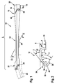
- an inventive wiper arm 10 is shown in a perspective view.
- This essentially comprises a joint part 12 and a fastening part 14, which are connected to one another via a joint 16 such that the joint part 12 can be folded relative to the fastening part 14.
- a spring which is not shown here for reasons of clarity is tensioned as a bracing element, so that in the assembled state a bias is created between hinge part 12 and fastening part 14.
- the fastening part 14 is attached to a wiper shaft 18, which performs a pendulum motion during operation.
- the wiper arm 10 thereby oscillates in operation about the wiper shaft 18 in a plane which is approximately parallel to the surface of a wheel to be wiped, which is not shown here for reasons of clarity.
- the wiper arm 10 has a longitudinal extent L, along which a first end 20 is provided, on which the wiper arm 10 is fixed to the wiper shaft 18. Furthermore, the wiper arm 10 has along its longitudinal extent a second end 22 facing away from the first end 20, to which a wiper blade 24 can be fastened.
- a fastening means 26 is provided which may consist of eyelets, as shown here, or hooks or pins or other fasteners. In the example shown, two eyelets are provided, which are able to accommodate a pen not shown, so that the wiper blade 24 is able to oscillate in a plane parallel to the pendulum axis of the wiper shaft 18 level. Between the first end 20 and the second end 22, a central portion 28 is provided which is disposed between the hinge 16 and the second end 22.
- the joint 16 in this case comprises a hinge pin 30, which connects the fastening part 14 and the hinge part 12 with each other and thus forms an axis of rotation for folding.
- the hinge part 18 is thus collapsible in a plane parallel to the wiper shaft 18.
- FIG. 2 the central portion 28 of the joint part 12 of the wiper arm 10 according to the invention is shown in cross section.
- This central portion 28 has an inflow side 32, which faces in the mounted position on a motor vehicle in the direction of travel. The wind then hits this inflow side 32.
- the joint part 12 has on its inflow side 32 a wedge portion 34, which essentially comprises a back leg 36 and an end leg 38, which are connected by a wedge vertex 40.
- the back leg 36 is followed by a back 42. This is substantially perpendicular to the pendulum axis of the wiper shaft 18 (FIG. FIG. 1 ) and thus approximately parallel to the disk to be wiped.
- End legs 38 and back legs 36 include a wedge angle ⁇ that is about 80 degrees. The bisector of this angle is approximately parallel to the back 42 or cuts the plane formed by the back 42 level E on the upstream side 32nd
- the back leg 36 and back 42 also form an angle ⁇ that is about 40 degrees.
- the angle ⁇ in this case is the acute angle which the back leg 36 encloses with the plane E formed by the back 42 in cross section.
- the wedge angle ⁇ and the angle ⁇ can be varied accordingly.
- the end leg 38 encloses with the back 42 in this case an angle ⁇ , which is about 95 degrees. This angle can also be varied, in particular depending on the wiper blade 24 used.
- a rear side 44 is provided, which extends starting from the back 42 downwards in the direction of the disk not shown here.
- Back 42 and back 44 include here an angle ⁇ , which is between 85 and 95 degrees.
- the rear side 44 is here formed in two parts, so that a first, directly to the back 42 adjacent section and a second, adjoining the first section portion is formed.
- the first section includes the back 42 at an angle of about 95 degrees.
- the second section includes the back 42 at an angle of about 90 degrees.
- the first portion may also include an angle of about 100 degrees with the spine 42 and the second portion may enclose an angle of up to 60 degrees, preferably between 60 degrees and 160 degrees, with the spine 42.
- the wedge peak 40 has a distance a which is greater than the distance b between the plane E and the free end of the back 44.
- distances a, b may also be be equal.
- the distance b may be greater than the distance a.
- the central portion 28 may extend over almost the entire longitudinal extent L of the wiper arm 10. In a variation of the invention, however, the central portion 28 may extend only over a quarter or a third of the longitudinal extension of the wiper arm 10. In particular, the middle section 28 can also extend to the section of the wiper arm 10, in the region of which the wiper blade 24 extends. In a further variation of the invention, the central portion 28 extends over more than half the length of the hinge part 12, in particular such that the majority of the length of the central portion 28 extends in the half of the hinge part 12 facing the second end 22.
- the wiper blade 24 is in this case designed as a so-called flat bar wiper blade, which essentially comprises a spring rail, on the side facing the wafer a wiper lip and on the disc side facing away from a spoiler is attached.
- wiper blades which have become known from BOSCH under the name "Aerotwin"
- an optimum wiping result is achieved in cooperation with the wiper arm 10 according to the invention.
- the back 42, the back leg 36 or the end leg 38 may each be formed individually or in combination also convex or concave.
- the indicated angles in this case refer to the mean tangent angle, in particular in the middle cross-sectional area.
Landscapes
- Engineering & Computer Science (AREA)
- Mechanical Engineering (AREA)
- Pivots And Pivotal Connections (AREA)
- Transmission Devices (AREA)
- Connection Of Motors, Electrical Generators, Mechanical Devices, And The Like (AREA)
Claims (6)
- Bras d'essuie-glace (10), en particulier pour une vitre d'un véhicule automobile, comprenant une étendue longitudinale (L) le long de laquelle une première extrémité (20) est prévue pour être fixée à un arbre d'essuie-glace (18) et une deuxième extrémité (22) est prévue pour la fixation d'un balai d'essuie-glace (24), entre lesquelles au moins une portion centrale (28) est réalisée, laquelle présente, en section transversale, un côté d'afflux (32) tourné dans l'état monté dans la direction de conduite du véhicule automobile, et un côté de sortie (35) opposé, en section transversale, au côté d'afflux (32), et sur le côté d'afflux (32), en section transversale, présente une portion de clavette (34) avec une branche de dos (36), une branche terminale (38) et une branche de clavette (40), entre le côté d'afflux (32) et le côté de sortie (35) étant prévu un dos (42), qui, dans l'état monté, est disposé en particulier parallèlement à la vitre, et un côté arrière (44) s'étend depuis le dos (42), lequel forme au moins en partie avec le dos (42) un angle (γ) d'environ 90 degrés, notamment compris entre 85 et 110 degrés, notamment entre 90 et 100 degrés, caractérisé en ce qu'en section transversale, la distance a entre un plan (E) formé par le dos (42) et le sommet de clavette (40) est supérieure à la distance b entre le plan et l'extrémité libre du côté arrière (44).
- Bras d'essuie-glace (10) selon la revendication 1, caractérisé en ce que la portion de clavette (34) présente entre la branche de dos (36) et la branche terminale (38) un angle de clavette (α) qui est inférieur ou égal à 90 degrés, en particulier qui est inférieur à 85 degrés, de préférence inférieur à 75 degrés.
- Bras d'essuie-glace (10) selon la revendication 2, caractérisé en ce que la branche de dos (36) et le dos (42) forment un angle (β) qui est supérieur à 0 degrés, en particulier qui est supérieur à 15 degrés, de préférence supérieur à 35 degrés ou égal à 45 degrés, et en particulier qui est inférieur à 80 degrés.
- Bras d'essuie-glace (10) selon la revendication 2, caractérisé en ce que la branche terminale (38) forme avec le dos (42) un angle (δ) qui est inférieur à 95 degrés, notamment à 75 degrés, de préférence qui est inférieur ou égal à 50 degrés.
- Bras d'essuie-glace (10) selon l'une quelconque des revendications précédentes, caractérisé en ce que le long de l'étendue longitudinale (L) est prévue une articulation (16) pour le rabattement et l'au moins une portion centrale (28) est disposée entre l'articulation (16) et la deuxième extrémité (22).
- Bras d'essuie-glace (10) selon l'une quelconque des revendications précédentes, caractérisé en ce que la portion centrale (28) est réalisée en tôle, en particulier en tôle estampée cintrée, ou en plastique.
Applications Claiming Priority (2)
| Application Number | Priority Date | Filing Date | Title |
|---|---|---|---|
| DE102006004773 | 2006-02-02 | ||
| DE102006013965A DE102006013965A1 (de) | 2006-02-02 | 2006-03-27 | Wischerarm, insbesondere für ein Kraftfahrzeug |
Publications (3)
| Publication Number | Publication Date |
|---|---|
| EP1816043A2 EP1816043A2 (fr) | 2007-08-08 |
| EP1816043A3 EP1816043A3 (fr) | 2009-09-09 |
| EP1816043B1 true EP1816043B1 (fr) | 2011-06-15 |
Family
ID=37808212
Family Applications (1)
| Application Number | Title | Priority Date | Filing Date |
|---|---|---|---|
| EP20060126671 Not-in-force EP1816043B1 (fr) | 2006-02-02 | 2006-12-20 | Bras d'essuie-glace, en particulier pour un véhicule automobile |
Country Status (3)
| Country | Link |
|---|---|
| EP (1) | EP1816043B1 (fr) |
| BR (1) | BRPI0700177A (fr) |
| DE (1) | DE102006013965A1 (fr) |
Cited By (1)
| Publication number | Priority date | Publication date | Assignee | Title |
|---|---|---|---|---|
| CN105270341A (zh) * | 2014-07-17 | 2016-01-27 | 法雷奥系统公司 | 在雨刮器臂和雨刮器刮片之间的连接设备 |
Families Citing this family (1)
| Publication number | Priority date | Publication date | Assignee | Title |
|---|---|---|---|---|
| DE102016206159A1 (de) | 2016-04-13 | 2017-10-19 | Robert Bosch Gmbh | Wischarmvorrichtung |
Family Cites Families (5)
| Publication number | Priority date | Publication date | Assignee | Title |
|---|---|---|---|---|
| DE19833939A1 (de) * | 1997-07-29 | 1999-02-04 | Asmo Co Ltd | Wischerarm und Wischervorrichtung für ein Fahrzeug |
| DE19750190A1 (de) | 1997-11-13 | 1999-05-20 | Bosch Gmbh Robert | Wischvorrichtung für Scheiben von Kraftfahrzeugen mit einem langgestreckten, einendig am Kraftfahrzeug geführten, angetriebenen Wischerarm |
| FR2785248B1 (fr) * | 1998-10-28 | 2000-12-01 | Valeo Systemes Dessuyage | Bras d'essuie-glace conforme en deflecteur aerodynamique |
| DE19957741A1 (de) * | 1999-12-01 | 2001-06-07 | Bosch Gmbh Robert | Wischvorrichtung für Scheiben von Kraftfahrzeugen |
| DE10308785B4 (de) * | 2003-02-28 | 2018-01-04 | Robert Bosch Gmbh | Wischvorrichtung |
-
2006
- 2006-03-27 DE DE102006013965A patent/DE102006013965A1/de not_active Ceased
- 2006-12-20 EP EP20060126671 patent/EP1816043B1/fr not_active Not-in-force
-
2007
- 2007-02-01 BR BRPI0700177 patent/BRPI0700177A/pt not_active IP Right Cessation
Cited By (1)
| Publication number | Priority date | Publication date | Assignee | Title |
|---|---|---|---|---|
| CN105270341A (zh) * | 2014-07-17 | 2016-01-27 | 法雷奥系统公司 | 在雨刮器臂和雨刮器刮片之间的连接设备 |
Also Published As
| Publication number | Publication date |
|---|---|
| BRPI0700177A (pt) | 2007-11-06 |
| DE102006013965A1 (de) | 2007-08-16 |
| EP1816043A2 (fr) | 2007-08-08 |
| EP1816043A3 (fr) | 2009-09-09 |
Similar Documents
| Publication | Publication Date | Title |
|---|---|---|
| DE112007002556B4 (de) | Wischersystem mit einem Stift-Wischerarm und Wischeranordnung | |
| EP0929423B1 (fr) | Raclette d'essuie-glace pour vitres de vehicules automobiles | |
| EP1375273B1 (fr) | Dispositif d'essuie-glace | |
| EP1363816B1 (fr) | Bras d'essuie-glace pourvu d'une raclette reliee de maniere articulee | |
| EP2331372B1 (fr) | Raclette d'essuie-glace et assemblage realise entre un bras et une raclette d'un essuie-glace | |
| DE10162399A1 (de) | Scheibenwischer mit einem Wischarm | |
| EP1289806A1 (fr) | Raclette d'essuie-glace pour le nettoyage de vitres, notamment de vehicules automobiles | |
| DE102013222993A1 (de) | Scheibenwischvorrichtung | |
| EP3044045B1 (fr) | Dispositif de fixation pour dispositif essuie-glace | |
| EP1816043B1 (fr) | Bras d'essuie-glace, en particulier pour un véhicule automobile | |
| EP1296862A1 (fr) | Bras d'essuie-glace pour automobiles | |
| WO2016012264A1 (fr) | Dispositif de fixation pour dispositif d'essuie-glace | |
| DE102013222996A1 (de) | Scheibenwischvorrichtung | |
| EP1720749B1 (fr) | Bras de dispositif d'essuie-glace | |
| WO2001040033A1 (fr) | Dispositif essuie-glace pour vitres de vehicule automobile | |
| DE102008017250B4 (de) | Geräuschgedämpftes Wischerblatt für einen Scheibenwischer an einem Fahrzeug | |
| DE69202188T2 (de) | Lamellenluftleitblech, insbesondere für Kraftfahrzeuge. | |
| WO2015032579A1 (fr) | Charnière pelliculaire pour un dispositif d'essuie-glace | |
| DE102016226269A1 (de) | Flachbalkenwischblatt | |
| EP1818227B1 (fr) | Bras d'essuie-glace, en particulier pour un véhicule | |
| DE102012221672A1 (de) | Wischerarm und Wischhebel | |
| DE102024207682A1 (de) | Wischblatt, insbesondere für ein Kraftfahrzeug | |
| DE102013222994A1 (de) | Scheibenwischvorrichtung | |
| DE102016010696A1 (de) | Wischeranordnung für eine Fahrzeugscheibe | |
| WO2024083679A1 (fr) | Balai d'essuie-glace, en particulier pour un véhicule automobile |
Legal Events
| Date | Code | Title | Description |
|---|---|---|---|
| PUAI | Public reference made under article 153(3) epc to a published international application that has entered the european phase |
Free format text: ORIGINAL CODE: 0009012 |
|
| AK | Designated contracting states |
Kind code of ref document: A2 Designated state(s): AT BE BG CH CY CZ DE DK EE ES FI FR GB GR HU IE IS IT LI LT LU LV MC NL PL PT RO SE SI SK TR |
|
| AX | Request for extension of the european patent |
Extension state: AL BA HR MK YU |
|
| PUAL | Search report despatched |
Free format text: ORIGINAL CODE: 0009013 |
|
| AK | Designated contracting states |
Kind code of ref document: A3 Designated state(s): AT BE BG CH CY CZ DE DK EE ES FI FR GB GR HU IE IS IT LI LT LU LV MC NL PL PT RO SE SI SK TR |
|
| AX | Request for extension of the european patent |
Extension state: AL BA HR MK RS |
|
| 17P | Request for examination filed |
Effective date: 20100309 |
|
| AKX | Designation fees paid |
Designated state(s): BE DE ES FR GB |
|
| 17Q | First examination report despatched |
Effective date: 20100504 |
|
| GRAP | Despatch of communication of intention to grant a patent |
Free format text: ORIGINAL CODE: EPIDOSNIGR1 |
|
| RIC1 | Information provided on ipc code assigned before grant |
Ipc: B60S 1/40 20060101AFI20110215BHEP Ipc: B60S 1/32 20060101ALI20110215BHEP |
|
| GRAS | Grant fee paid |
Free format text: ORIGINAL CODE: EPIDOSNIGR3 |
|
| GRAA | (expected) grant |
Free format text: ORIGINAL CODE: 0009210 |
|
| AK | Designated contracting states |
Kind code of ref document: B1 Designated state(s): BE DE ES FR GB |
|
| REG | Reference to a national code |
Ref country code: GB Ref legal event code: FG4D Free format text: NOT ENGLISH |
|
| REG | Reference to a national code |
Ref country code: DE Ref legal event code: R096 Ref document number: 502006009660 Country of ref document: DE Effective date: 20110728 |
|
| REG | Reference to a national code |
Ref country code: ES Ref legal event code: FG2A Ref document number: 2363985 Country of ref document: ES Kind code of ref document: T3 Effective date: 20110822 |
|
| PLBE | No opposition filed within time limit |
Free format text: ORIGINAL CODE: 0009261 |
|
| STAA | Information on the status of an ep patent application or granted ep patent |
Free format text: STATUS: NO OPPOSITION FILED WITHIN TIME LIMIT |
|
| 26N | No opposition filed |
Effective date: 20120316 |
|
| REG | Reference to a national code |
Ref country code: DE Ref legal event code: R097 Ref document number: 502006009660 Country of ref document: DE Effective date: 20120316 |
|
| PGFP | Annual fee paid to national office [announced via postgrant information from national office to epo] |
Ref country code: ES Payment date: 20141215 Year of fee payment: 9 Ref country code: GB Payment date: 20141216 Year of fee payment: 9 |
|
| PGFP | Annual fee paid to national office [announced via postgrant information from national office to epo] |
Ref country code: BE Payment date: 20141211 Year of fee payment: 9 |
|
| REG | Reference to a national code |
Ref country code: FR Ref legal event code: PLFP Year of fee payment: 10 |
|
| PGFP | Annual fee paid to national office [announced via postgrant information from national office to epo] |
Ref country code: FR Payment date: 20151218 Year of fee payment: 10 |
|
| PGFP | Annual fee paid to national office [announced via postgrant information from national office to epo] |
Ref country code: DE Payment date: 20160224 Year of fee payment: 10 |
|
| PG25 | Lapsed in a contracting state [announced via postgrant information from national office to epo] |
Ref country code: BE Free format text: LAPSE BECAUSE OF NON-PAYMENT OF DUE FEES Effective date: 20151231 |
|
| GBPC | Gb: european patent ceased through non-payment of renewal fee |
Effective date: 20151220 |
|
| PG25 | Lapsed in a contracting state [announced via postgrant information from national office to epo] |
Ref country code: GB Free format text: LAPSE BECAUSE OF NON-PAYMENT OF DUE FEES Effective date: 20151220 |
|
| PG25 | Lapsed in a contracting state [announced via postgrant information from national office to epo] |
Ref country code: ES Free format text: LAPSE BECAUSE OF NON-PAYMENT OF DUE FEES Effective date: 20151221 |
|
| REG | Reference to a national code |
Ref country code: DE Ref legal event code: R119 Ref document number: 502006009660 Country of ref document: DE |
|
| REG | Reference to a national code |
Ref country code: FR Ref legal event code: ST Effective date: 20170831 |
|
| PG25 | Lapsed in a contracting state [announced via postgrant information from national office to epo] |
Ref country code: FR Free format text: LAPSE BECAUSE OF NON-PAYMENT OF DUE FEES Effective date: 20170102 |
|
| PG25 | Lapsed in a contracting state [announced via postgrant information from national office to epo] |
Ref country code: DE Free format text: LAPSE BECAUSE OF NON-PAYMENT OF DUE FEES Effective date: 20170701 |
|
| REG | Reference to a national code |
Ref country code: ES Ref legal event code: FD2A Effective date: 20180706 |