EP1816059B1 - Poids lourd accouplé au véhicule tracteur par un col de cygne - Google Patents
Poids lourd accouplé au véhicule tracteur par un col de cygne Download PDFInfo
- Publication number
- EP1816059B1 EP1816059B1 EP20070101457 EP07101457A EP1816059B1 EP 1816059 B1 EP1816059 B1 EP 1816059B1 EP 20070101457 EP20070101457 EP 20070101457 EP 07101457 A EP07101457 A EP 07101457A EP 1816059 B1 EP1816059 B1 EP 1816059B1
- Authority
- EP
- European Patent Office
- Prior art keywords
- displacer
- positive
- heavy load
- hydraulic
- chamber
- Prior art date
- Legal status (The legal status is an assumption and is not a legal conclusion. Google has not performed a legal analysis and makes no representation as to the accuracy of the status listed.)
- Active
Links
Images

Classifications
-
- B—PERFORMING OPERATIONS; TRANSPORTING
- B62—LAND VEHICLES FOR TRAVELLING OTHERWISE THAN ON RAILS
- B62D—MOTOR VEHICLES; TRAILERS
- B62D53/00—Tractor-trailer combinations; Road trains
- B62D53/04—Tractor-trailer combinations; Road trains comprising a vehicle carrying an essential part of the other vehicle's load by having supporting means for the front or rear part of the other vehicle
- B62D53/06—Semi-trailers
- B62D53/061—Semi-trailers of flat bed or low loader type or fitted with swan necks
- B62D53/062—Semi-trailers of flat bed or low loader type or fitted with swan necks having inclinable, lowerable platforms; Lift bed trailers; Straddle trailers
-
- B—PERFORMING OPERATIONS; TRANSPORTING
- B62—LAND VEHICLES FOR TRAVELLING OTHERWISE THAN ON RAILS
- B62D—MOTOR VEHICLES; TRAILERS
- B62D53/00—Tractor-trailer combinations; Road trains
- B62D53/04—Tractor-trailer combinations; Road trains comprising a vehicle carrying an essential part of the other vehicle's load by having supporting means for the front or rear part of the other vehicle
- B62D53/06—Semi-trailers
- B62D53/061—Semi-trailers of flat bed or low loader type or fitted with swan necks
- B62D53/062—Semi-trailers of flat bed or low loader type or fitted with swan necks having inclinable, lowerable platforms; Lift bed trailers; Straddle trailers
- B62D53/065—Semi-trailers of flat bed or low loader type or fitted with swan necks having inclinable, lowerable platforms; Lift bed trailers; Straddle trailers inclining platforms by detachable or folding swan necks
-
- B—PERFORMING OPERATIONS; TRANSPORTING
- B62—LAND VEHICLES FOR TRAVELLING OTHERWISE THAN ON RAILS
- B62D—MOTOR VEHICLES; TRAILERS
- B62D53/00—Tractor-trailer combinations; Road trains
- B62D53/04—Tractor-trailer combinations; Road trains comprising a vehicle carrying an essential part of the other vehicle's load by having supporting means for the front or rear part of the other vehicle
- B62D53/06—Semi-trailers
- B62D53/068—Semi-trailers having devices to equalise or modify the load between the fifth wheel and the rear wheels
Definitions
- Such a heavy load vehicle is from the GB 1,420,634 known.
- the heavy load vehicle described therein has a towing vehicle which is coupled to the heavy load vehicle via a gooseneck which can be mounted on the towing vehicle.
- a hydraulic displacer arrangement is arranged, the hydraulic pressures of which determine the load removed from the gooseneck to the towing vehicle.
- the load transmitted by the displacer assembly is determined by the wheel load acting on a wheel set of the heavy load vehicle. Radabstützaggregate communicating with the displacer assembly thus determine the hydraulic pressures in the displacer assembly.
- a disadvantage of the known heavy-load vehicle is that the ratio between the load carried on the towing vehicle and the wheel loads of the heavy-duty vehicle can not be changed.
- the DE 20 2005 007 524 U1 describes a gooseneck for a heavy duty vehicle, the gooseneck comprising a rigidly connectable to a platform of a trailer and detachable from this plate and an arm for supporting on a saddle of a tractor.
- the arm has a projecting coupling pin for coupling to the tractor's saddle and is connected by a support to the plate.
- a hydraulic cylinder controls the positioning of the coupling pin with respect to the plate.
- protruding coupling pin has provided coupling plate, which surrounds the arm around a. Transverse pin rotates under the action of the hydraulic control cylinder, which is connected to the plate and supported on the arm which is rigidly connected to the support, which in turn is rigidly connected to the plate via its foot.
- a heavy load vehicle in which the entire gooseneck or its saddle on the fifth wheel of the towing vehicle coupling part is supported by a hydraulic displacer height-adjustable, so that the hydraulic pressure in Verdrängeraan Aunt is a measure of the abraded load on the towing vehicle. Since the displacer arrangement in turn communicates hydraulically with hydraulic Radabstützaggregaten the heavy load vehicle, the hydraulic pressure in the displacer assembly is also dependent on the weight of the load transported on the heavy load vehicle or the wheel loads caused by it. As a result, so also increased load on the towing vehicle is removed at increased wheel load.
- a hydraulic two-circuit system is provided such that an arranged on one side of the vehicle unit of the gooseneck associated displacer only communicates with Radabstützaggregaten on this side of the vehicle, while arranged on the other side of the vehicle further aggregate of the displacer only in hydraulic connection with Radabstützaggregaten on the other side of the vehicle stands.
- the loading platform can be lowered during loading on the ground or the road.
- the semi-trailer has hydraulic Verdfiteraggregate with which the wheels of the semi-trailer can be adjusted relative to the loading platform corresponding far far vertically.
- Further hydraulic positive displacement units are provided which allow height adjustment of the gooseneck with respect to the loading platform, so that the semi-trailer can be separated from the towing vehicle when lying on the ground loading platform or the towing vehicle can go under the gooseneck for coupling the semi-trailer.
- the invention is related to the problem of being able to alter the relationship between the load borne by the towing vehicle and the wheel loads of those wheels of the heavy duty vehicle associated with the wheel support assemblies communicating with the displacer assembly of the gooseneck.
- hitherto available on the market heavy duty vehicles is provided for this purpose, to install the displacer assembly on the gooseneck in different positions, such that the transmission ratio between the hydraulic pressure in the displacer assembly and the load carried on the towing vehicle is changed.
- it is problematic that the assembly of the displacer can be done incorrectly and thus must be reckoned with serious damage to the heavy truck. Accordingly, it is the object of the invention to provide an arrangement with which the ratio between the load carried by the towing vehicle and the wheel loads can be changed or adjusted with high reliability.
- the positive displacement and negative chambers wherein the hydraulic pressures in the positive chambers lead to actuating forces, which counteract the actuation forces caused by the hydraulic pressures in the negative chambers, so that by the positive - And negative chambers generated hydraulic pressures cause opposing forces in the tensile or shear direction of the displacer, and in specifiable combination with the Radabstützaggregaten and / or a relatively pressureless Hydraulic reservoir are connectable, that the displacer arrangement comprises a first and a second displacer part, the first displacer part has a tubular piston rod with an annular piston arranged at the end and facing the second displacer part, said piston being displaceably arranged in an annular space of the second displacer part, thereby separating a first working chamber from a second working chamber, that the first working chamber forms one of the two positive chambers and the second working chamber forms the negative chamber and that the second displacer part has a plunger
- the invention is thus based on the general idea of designing the displacer arrangement associated with the gooseneck as a multi-chamber system, wherein the hydraulic pressures in the one chambers (positive chambers) lead to actuating forces which counteract the actuating forces caused by the hydraulic pressures in other chambers (negative chambers).
- the hydraulic pressures in the one chambers positive chambers
- the hydraulic pressures in other chambers negative chambers
- only one Umschaltventilan angel is required to connect the various chambers of the displacer in different combinations either with the relatively pressureless hydraulic reservoir or the Radabstützaggregaten. Operating errors or even incorrect assembly are thus excluded.
- the displacer arrangement has a first and a second positive chamber which can be fluidly separated therefrom.
- the displacer assembly is pressure-connected to hydraulic Radabstweilaggregaten the vehicle wheels. This causes the fifth wheel load generated by the displacer assembly to be dependent on the load to be transported picked up by the heavy load vehicle.
- High loads thus mean high pressure in Radabstützaggregaten and at the same time a high pressure in the displacer assembly, which then generates a correspondingly high saddle load over the gooseneck to the large load to be transported.
- the fifth-wheel load in turn is responsible for the axle load of the towing vehicle, so that the axle load of the towing vehicle and thus its traction with a roadway can be determined by the pressure connection between the displacer assembly and the RadabstNeillaggregaten the heavy load vehicle.
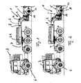
- a heavy load vehicle 1 which is coupled via a gooseneck 2 with a towing vehicle 3, between a chassis of the heavy load vehicle 1 and the gooseneck 2, at least one displacer 4.
- a towing vehicle 3 between a chassis of the heavy load vehicle 1 and the gooseneck 2, at least one displacer 4.
- a heavy load vehicle 1 which is coupled via a gooseneck 2 with a towing vehicle 3, between a chassis of the heavy load vehicle 1 and the gooseneck 2, at least one displacer 4.
- axis line A is shown, wherein such heavy-duty vehicles 1 normally have further arranged in the direction of travel behind this axis line A axle lines.
- large loads such as construction machines, can be transported.
- the tractor 3 according to the embodiments of the Fig. 1 and 2 a total of four axes, wherein at least the frontmost axis in the direction of travel is equipped with steerable wheels 6.
- the towing vehicle 3 is coupled to the heavy load vehicle 1, wherein an over the gooseneck 2 acting on the towing vehicle 3 fifth wheel load determines the axle loads of the towing vehicle 3 and thus its traction.
- the prevailing in the displacer 4 pressure is determined by the load to be transported.
- the gooseneck 2 is according to the Fig. 1 and 2 about a substantially parallel to the axes of the towing vehicle 3 and the heavy load vehicle 1 extending axis 8 (perpendicular to the image plane) bendable.
- the buckling possibility is thereby in the consideration of Fig. 2 unlike Fig. 1 clear.
- a buckling counterclockwise is possible.
- this is coupled to the towing vehicle 3 via the coupling 7, whereas it is pivotally connected to the puller 3 remote end 22 to the displacer 4.
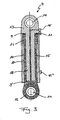
- Fig. 3 has the displacer 4 constructed as a 3-area lifting cylinder two positive chambers 9 and 9 'and a negative chamber 10, which are acted upon in a predeterminable combination with hydraulic medium.
- the two positive chambers 9, 9 'and the negative chamber 10 have different cross-sectional areas.
- An increase in the hydraulic volume in the positive chambers 9 and 9 ' causes at the same time unpressurized negative chamber 10, an extension of the displacer 4, whereas a pressure medium supply into the negative chamber 10 at the same time unpressurized positive chambers 9 causes a shortening or a contraction of the displacer 4.
- the displacer assembly 4 consists of a first displacer part 12 and a cooperating second displacer part 13 and preferably has a substantially cylindrical shape.
- each of the displacer parts 12, 13 each have a bearing eye 14, via which the displacer assembly 4 can be articulated, for example, by means of a bolt on the gooseneck 2 or on the heavy-duty vehicle 1.
- the first displacer part 12 has a tubular piston rod 15 with an annular piston 16 arranged at the end and facing the second displacer part 13.
- the annular piston 16 is displaceably arranged in an annular space 17 of the second displacer part 13, which simultaneously forms the negative chamber 10, and separates according to FIG Fig. 3 the positive chamber 9 from the negative chamber 10th
- the second displacer part 13 has a plunger-like piston 18, which is displaceably mounted in the tube interior in the piston rod 15 of the first displacer part 12.
- the first displacement member 12 and the plunger-like piston 18 thereby limit the second positive chamber 9 ', wherein a hydraulic Supply line to the second positive chamber 9 'substantially centrally in the plunger-like piston 18 extends close to the recess 14 and is then guided radially outwardly to the connecting line 11'.
- the negative chamber 10 is connected via a connecting line 11 "to the hydraulic system.
- the displacer assembly 4 with hydraulic Radabstützaggregaten 19 of the vehicle wheels 20 of the heavy load vehicle 1 is pressure-connected (see. Fig. 1 ).
- a load to be transported on the bed 5 of the heavy duty vehicle 1 determines the pressure in the hydraulic Radabstützaggregaten 19 and thus also a hydraulic pressure in the displacer 4.
- the so predetermined on the load to be transported hydraulic pressure in the displacer 4 again determines the gooseneck 2 to the coupling 7 and the towing vehicle 3 to be transmitted fifth wheel load.
- the fifth wheel load is dependent on the load to be transported and no longer dependent on a selected for the displacement assembly 4 articulation point on the gooseneck 2. It is possible depending on the desired height level to pump a larger or smaller hydraulic volume in the Radabstützaggregate 19 of the vehicle wheels 20 ,
- the displacer 4 is connected via a valve assembly 24 with the Radabstützaggregaten 19.
- the wheel support units 19 can be interconnected into three independent groups, resulting in the best case, a three-point support of the heavy truck 1 results on the road.
- a three-point support can be done, for example, by interconnecting a plurality of front axle lines of the heavy load vehicle 1 in the direction of travel and by a page-wise interconnection of the axis lines of the heavy load vehicle 1 located behind in the direction of travel.
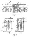
- Fig. 4 a possible mounting form of the displacer 4 is shown on the gooseneck 2, wherein each displacer assembly 4 is connected via connecting lines 11 both with a substantially unpressurized hydraulic reservoir 23 and with at least two Radabstützaggregaten 19.
- Each positive chamber 9 and 9 'and the negative chamber 10 is preceded by an associated valve 25, which is part of the valve assembly 24, so that the individual positive chambers 9 and 9' and the negative chamber 10 are connected to the hydraulic system or be separated from it can.
- the hydraulic pressure prevailing in the hydraulic system or in the connecting lines 11 is determined by the dead weight of the heavy-duty vehicle 1 or by a load to be transported on its loading surface 5.
- the over the gooseneck 2 to the towing vehicle 3 to be transmitted to the fifth wheel load on the position of the valves 25, 25 ', 25 are influenced, so that always the required axle for traction axle load is reached.
- the valves 25th and 25 'set so that the two positive chambers 9 and 9' can be acted upon with hydraulic medium, while the negative chamber 10 with the pressure-less in itself and according to the Fig. 5a not shown hydraulic reservoir 23 is connected.
- the two positive chambers 9 and 9 ' act together.
- valves 25, 25', 25 can thus only by a simple change in the valve positions six different actuating forces in the displacer 4.
- the valves 25, 25 ', 25 may in this case be from a closed to a fully opened, partially open position Condition are transferred and vice versa.
- valves 25, 25 'and 25 “and the different cross-sectional areas of the two positive chambers 9, 9' and the negative chamber 10 it is possible to generate different fifth-wheel loads which are adapted to the respective tractor 3 and for a sufficient axle load the driven axles so that the towing vehicle 3 can transmit the traction force reliably to the roadway, whereby the number of axles of the towing vehicle can also be taken into account.
Landscapes
- Engineering & Computer Science (AREA)
- Chemical & Material Sciences (AREA)
- Combustion & Propulsion (AREA)
- Transportation (AREA)
- Mechanical Engineering (AREA)
- Vehicle Body Suspensions (AREA)
Claims (4)
- Poids lourd (1) avec- un col de cygne (2) pouvant être semi-porté sur un véhicule tracteur (3) pour l'accouplement du poids lourd (1) au véhicule tracteur,- un dispositif de refoulement hydraulique (4) associé au col de cygne (2) dont les pressions hydrauliques déterminent la charge transférée par le col de cygne (2) sur le véhicule tracteur (3) et- plusieurs groupes supports de roues (19) qui sont en communication hydraulique avec le dispositif de refoulement (4) et qui déterminent ainsi les pressions hydrauliques dans le dispositif de refoulement (4),caractérisé en ce que- le dispositif de refoulement (4) comporte des chambres positives et négatives (9, 9' ; 10) qui peuvent être reliées selon une combinaison prédéterminée aux groupes supports de roues (19) et/ou à un réservoir hydraulique relativement sans pression (23), dans lequel les pressions hydrauliques dans les chambres positives entrainent des forces de réglage qui s'opposent aux forces de réglage induites par les pressions hydrauliques dans les chambres négatives, de sorte que les pressions hydrauliques générées par les chambres positives et négatives (9, 9' ; 10) induisent des forces opposées les unes aux autres dans le sens de traction ou de poussée du dispositif de refoulement (4),- le dispositif de refoulement (4) comporte une première (12) et une seconde (13) partie de refoulement,- la première partie de refoulement (12) comporte une tige de piston tubulaire (15) avec un piston annulaire (16) disposé à l'extrémité de celle-ci et dirigé vers la seconde partie de refoulement (13), qui est disposé de manière déplaçable dans un espace annulaire (17) de la seconde partie de refoulement (13) et qui sépare ainsi une première chambre de travail d'une deuxième chambre de travail,- la première chambre de travail forme l'une des deux chambres positives (9, 9') et la deuxième chambre de travail forme la chambre négative (10) et- la seconde partie de refoulement (13) comporte un piston de type plongeur (18) qui est logé de manière déplaçable à l'intérieur du tube dans la tige de piston (15) de la première partie de refoulement (12), et- la première partie de refoulement (12) et le piston de type plongeur (18) de la seconde partie de refoulement (13) délimitent une troisième chambre de travail,- dans lequel la troisième chambre de travail forme la seconde chambre positive (9') et le dispositif de refoulement (4) peut être connecté directement ou indirectement à au moins un groupe support de roues (19) ou à un réservoir hydraulique au moyen d'un dispositif de soupape (24) comportant au moins une soupape (25).
- Poids lourd selon la revendication 1,
caractérisé en ce que le dispositif de refoulement (4) comporte une première (9) chambre positive et une seconde (9') chambre positive pouvant être séparée fluidiquement de la première chambre. - Poids lourd selon la revendication 1 ou 2,
caractérisé en ce que le poids lourds (1) comporte au moins deux modules de véhicule, un module de véhicule portant le col de cygne. - Poids lourd selon l'une quelconque des revendications 1 à 3,
caractérisé en ce que les groupes supports de roues (19) du poids lourd (1) peuvent être interconnectés en trois groupes indépendants les uns des autres pour permettre un appui à trois points du poids lourd (1) sur une voie de circulation.
Applications Claiming Priority (1)
| Application Number | Priority Date | Filing Date | Title |
|---|---|---|---|
| DE200610004930 DE102006004930A1 (de) | 2006-02-03 | 2006-02-03 | Mit einem Zugfahrzeug über einen Schwanenhals kuppelbares Schwerstlastfahrzeug |
Publications (2)
| Publication Number | Publication Date |
|---|---|
| EP1816059A1 EP1816059A1 (fr) | 2007-08-08 |
| EP1816059B1 true EP1816059B1 (fr) | 2009-02-25 |
Family
ID=37969909
Family Applications (1)
| Application Number | Title | Priority Date | Filing Date |
|---|---|---|---|
| EP20070101457 Active EP1816059B1 (fr) | 2006-02-03 | 2007-01-31 | Poids lourd accouplé au véhicule tracteur par un col de cygne |
Country Status (3)
| Country | Link |
|---|---|
| EP (1) | EP1816059B1 (fr) |
| DE (2) | DE102006004930A1 (fr) |
| ES (1) | ES2323093T3 (fr) |
Families Citing this family (6)
| Publication number | Priority date | Publication date | Assignee | Title |
|---|---|---|---|---|
| DE102009016725B4 (de) | 2009-04-09 | 2012-02-16 | Scheuerle Fahrzeugfabrik Gmbh | Schwanenhals für ein Fahrzeug, insbesondere für ein Schwerlastfahrzeug |
| EP2239188B9 (fr) | 2009-04-09 | 2012-08-15 | Scheuerle Fahrzeugfabrik GmbH | Col de cygne de véhicule, notamment pour véhicule gros porteur |
| DE202009005380U1 (de) | 2009-04-09 | 2010-01-14 | Scheuerle Fahrzeugfabrik Gmbh | Schwanenhals für ein Lastfahrzeug, insbesondere für ein Schwerlastfahrzeug |
| EP3601807B1 (fr) | 2017-03-23 | 2021-05-19 | Scheuerle Fahrzeugfabrik GmbH | Unité de commande pour un dispositif de commande pour un véhicule lourd, en particulier pour un couple de balançoire, un agencement de levage ou un dispositif de direction d'un véhicule lourd et un tel dispositif de commande |
| DE202017001550U1 (de) | 2017-03-23 | 2018-06-28 | Scheuerle Fahrzeugfabrik Gmbh | Steuereinheit für eine Steuerungsvorrichtung für ein Schwerlast-Fahrzeug, insbesondere für einen Schwanenhals, eine Hubanordnung oder eine Lenkanordnung eines Schwerlast-Fahrzeugs, sowie eine derartige Steuerungsvorrichtung |
| DE102017002784A1 (de) | 2017-03-23 | 2018-09-27 | Scheuerle Fahrzeugfabrik Gmbh | Steuereinheit für eine Steuerungsvorrichtung für ein Schwerlast-Fahrzeug, insbesondere für einen Schwanenhals, eine Hubanordnung oder eine Lenkanordnung eines Schwerlast-Fahrzeugs, sowie eine derartige Steuerungsvorrichtung |
Family Cites Families (5)
| Publication number | Priority date | Publication date | Assignee | Title |
|---|---|---|---|---|
| US2475443A (en) * | 1948-05-17 | 1949-07-05 | Robert O Bill | Semitrailer with body elevating and lowering means |
| AT328300B (de) | 1973-07-24 | 1976-03-10 | Goldhofer Fahrzeugwerk Kg | Fahrzeug mit einer zugmaschine und einem anhanger |
| FR2384665A1 (fr) * | 1977-03-24 | 1978-10-20 | Nicolas France Sa Jb | Perfectionnements aux attelages a semi-remorque |
| ES2038890B1 (es) * | 1991-05-10 | 1994-02-16 | Santamaria Felix Fernandez | Dispositivo para variar la carga sobre las ruedas de traccion de un vehiculo. |
| FR2870200B1 (fr) | 2004-05-13 | 2007-08-24 | Nicolas Ind | Col de cygne a essieu(s) integre(s) pour semi-remorque |
-
2006
- 2006-02-03 DE DE200610004930 patent/DE102006004930A1/de not_active Withdrawn
-
2007
- 2007-01-31 EP EP20070101457 patent/EP1816059B1/fr active Active
- 2007-01-31 ES ES07101457T patent/ES2323093T3/es active Active
- 2007-01-31 DE DE200750000450 patent/DE502007000450D1/de active Active
Also Published As
| Publication number | Publication date |
|---|---|
| DE102006004930A1 (de) | 2007-08-16 |
| ES2323093T3 (es) | 2009-07-06 |
| DE502007000450D1 (de) | 2009-04-09 |
| EP1816059A1 (fr) | 2007-08-08 |
Similar Documents
| Publication | Publication Date | Title |
|---|---|---|
| EP2238071B1 (fr) | Engin de travail mobile | |
| EP2240360B1 (fr) | Engin de travail mobile | |
| EP1816059B1 (fr) | Poids lourd accouplé au véhicule tracteur par un col de cygne | |
| EP0544727A1 (fr) | Vehicule. | |
| EP0266785A1 (fr) | Véhicule automobile polyvalent | |
| WO2019012045A2 (fr) | Sous-ensemble essieu pour poids-lourd, poids-lourd équipé d'au moins un tel sous-ensemble essieu et arrangement hydraulique, notamment destiné à positionner une unité positionnable réalisée sous la forme d'un arrangement de piston et cylindre | |
| WO2020025201A1 (fr) | Attelage comprenant un véhicule tracteur et une remorque, véhicule tracteur, remorque et procédé pour la distribution de charge par essieu dans un attelage | |
| DE2546485C3 (de) | Straßenfahrzeug mit absenkbarer Ladefläche | |
| EP1918137A2 (fr) | Remorqueur d'aéroport doté d'une suspension à air | |
| EP3427560B1 (fr) | Dispositif d'attelage | |
| DE1605068C3 (de) | Zugmaschine für die Verwendung auf Schiene und Straße | |
| DE202012102356U1 (de) | Anhängerfahrzeug mit Knickdeichsel | |
| EP2239188B9 (fr) | Col de cygne de véhicule, notamment pour véhicule gros porteur | |
| EP3909407A1 (fr) | Machine agricole tractée et procédé pour influencer une force d'appui d'une machine agricole tractée | |
| DE1932040A1 (de) | Gewichtsuebertragungskupplung | |
| EP3156310B1 (fr) | Véhicule auxiliaire agricole sans entraînement | |
| DE3404930C2 (de) | Kraftfahrzeug-Gliederzug | |
| EP3971066B1 (fr) | Tracteur pourvu de train de roulement à chenilles | |
| DE3239006A1 (de) | Fahrzeug mit einem um eine waagerechte achse verschwenkbaren koerperteil, der durch eine hydropneumatische aufhaengung abgestuetzt ist | |
| DE10215033A1 (de) | Landwirtschaftliches Anhängerfahrzeug mit einer Einrichtung zum Verschieben der Ladung | |
| DE102009040204B4 (de) | Fahrgestellvorrichtung mit einer Achslifteinheit | |
| DE102009016725B4 (de) | Schwanenhals für ein Fahrzeug, insbesondere für ein Schwerlastfahrzeug | |
| DE202009005380U1 (de) | Schwanenhals für ein Lastfahrzeug, insbesondere für ein Schwerlastfahrzeug | |
| AT392444B (de) | Gelaendegaengiges, zwei- oder mehrachsiges, gummibereiftes arbeitsfahrzeug | |
| DE102015115641A1 (de) | Landwirtschaftliches Fahrzeug |
Legal Events
| Date | Code | Title | Description |
|---|---|---|---|
| PUAI | Public reference made under article 153(3) epc to a published international application that has entered the european phase |
Free format text: ORIGINAL CODE: 0009012 |
|
| AK | Designated contracting states |
Kind code of ref document: A1 Designated state(s): AT BE BG CH CY CZ DE DK EE ES FI FR GB GR HU IE IS IT LI LT LU LV MC NL PL PT RO SE SI SK TR |
|
| AX | Request for extension of the european patent |
Extension state: AL BA HR MK YU |
|
| 17P | Request for examination filed |
Effective date: 20070825 |
|
| 17Q | First examination report despatched |
Effective date: 20071016 |
|
| AKX | Designation fees paid |
Designated state(s): BE DE ES FR IT NL |
|
| GRAP | Despatch of communication of intention to grant a patent |
Free format text: ORIGINAL CODE: EPIDOSNIGR1 |
|
| GRAS | Grant fee paid |
Free format text: ORIGINAL CODE: EPIDOSNIGR3 |
|
| GRAA | (expected) grant |
Free format text: ORIGINAL CODE: 0009210 |
|
| AK | Designated contracting states |
Kind code of ref document: B1 Designated state(s): BE DE ES FR IT NL |
|
| REF | Corresponds to: |
Ref document number: 502007000450 Country of ref document: DE Date of ref document: 20090409 Kind code of ref document: P |
|
| REG | Reference to a national code |
Ref country code: DE Ref legal event code: R096 Ref document number: 502007000450 Country of ref document: DE Effective date: 20090409 |
|
| REG | Reference to a national code |
Ref country code: ES Ref legal event code: FG2A Ref document number: 2323093 Country of ref document: ES Kind code of ref document: T3 |
|
| PLBE | No opposition filed within time limit |
Free format text: ORIGINAL CODE: 0009261 |
|
| STAA | Information on the status of an ep patent application or granted ep patent |
Free format text: STATUS: NO OPPOSITION FILED WITHIN TIME LIMIT |
|
| 26N | No opposition filed |
Effective date: 20091126 |
|
| REG | Reference to a national code |
Ref country code: DE Ref legal event code: R097 Ref document number: 502007000450 Country of ref document: DE Effective date: 20091126 |
|
| PGFP | Annual fee paid to national office [announced via postgrant information from national office to epo] |
Ref country code: NL Payment date: 20101221 Year of fee payment: 5 |
|
| PGFP | Annual fee paid to national office [announced via postgrant information from national office to epo] |
Ref country code: FR Payment date: 20110201 Year of fee payment: 5 Ref country code: IT Payment date: 20110129 Year of fee payment: 5 |
|
| PGFP | Annual fee paid to national office [announced via postgrant information from national office to epo] |
Ref country code: BE Payment date: 20110124 Year of fee payment: 5 |
|
| PGFP | Annual fee paid to national office [announced via postgrant information from national office to epo] |
Ref country code: ES Payment date: 20110121 Year of fee payment: 5 |
|
| BERE | Be: lapsed |
Owner name: SCHEUERLE FAHRZEUGFABRIK G.M.B.H. Effective date: 20120131 |
|
| REG | Reference to a national code |
Ref country code: NL Ref legal event code: V1 Effective date: 20120801 |
|
| REG | Reference to a national code |
Ref country code: FR Ref legal event code: ST Effective date: 20120928 |
|
| PG25 | Lapsed in a contracting state [announced via postgrant information from national office to epo] |
Ref country code: IT Free format text: LAPSE BECAUSE OF NON-PAYMENT OF DUE FEES Effective date: 20120131 |
|
| PG25 | Lapsed in a contracting state [announced via postgrant information from national office to epo] |
Ref country code: FR Free format text: LAPSE BECAUSE OF NON-PAYMENT OF DUE FEES Effective date: 20120131 Ref country code: BE Free format text: LAPSE BECAUSE OF NON-PAYMENT OF DUE FEES Effective date: 20120131 |
|
| PG25 | Lapsed in a contracting state [announced via postgrant information from national office to epo] |
Ref country code: NL Free format text: LAPSE BECAUSE OF NON-PAYMENT OF DUE FEES Effective date: 20120801 |
|
| REG | Reference to a national code |
Ref country code: ES Ref legal event code: FD2A Effective date: 20131021 |
|
| PG25 | Lapsed in a contracting state [announced via postgrant information from national office to epo] |
Ref country code: ES Free format text: LAPSE BECAUSE OF NON-PAYMENT OF DUE FEES Effective date: 20120201 |
|
| P01 | Opt-out of the competence of the unified patent court (upc) registered |
Effective date: 20230515 |
|
| PGFP | Annual fee paid to national office [announced via postgrant information from national office to epo] |
Ref country code: DE Payment date: 20250430 Year of fee payment: 19 |