EP1816093A1 - Weichenvorrichtung für eine Fördereinrichtung - Google Patents
Weichenvorrichtung für eine Fördereinrichtung Download PDFInfo
- Publication number
- EP1816093A1 EP1816093A1 EP06425061A EP06425061A EP1816093A1 EP 1816093 A1 EP1816093 A1 EP 1816093A1 EP 06425061 A EP06425061 A EP 06425061A EP 06425061 A EP06425061 A EP 06425061A EP 1816093 A1 EP1816093 A1 EP 1816093A1
- Authority
- EP
- European Patent Office
- Prior art keywords
- switcher
- support element
- guide channel
- cursor
- channel
- Prior art date
- Legal status (The legal status is an assumption and is not a legal conclusion. Google has not performed a legal analysis and makes no representation as to the accuracy of the status listed.)
- Granted
Links
Images


Classifications
-
- B—PERFORMING OPERATIONS; TRANSPORTING
- B65—CONVEYING; PACKING; STORING; HANDLING THIN OR FILAMENTARY MATERIAL
- B65G—TRANSPORT OR STORAGE DEVICES, e.g. CONVEYORS FOR LOADING OR TIPPING, SHOP CONVEYOR SYSTEMS OR PNEUMATIC TUBE CONVEYORS
- B65G47/00—Article or material-handling devices associated with conveyors; Methods employing such devices
- B65G47/52—Devices for transferring articles or materials between conveyors i.e. discharging or feeding devices
- B65G47/68—Devices for transferring articles or materials between conveyors i.e. discharging or feeding devices adapted to receive articles arriving in one layer from one conveyor lane and to transfer them in individual layers to more than one conveyor lane or to one broader conveyor lane, or vice versa, e.g. combining the flows of articles conveyed by more than one conveyor
- B65G47/71—Devices for transferring articles or materials between conveyors i.e. discharging or feeding devices adapted to receive articles arriving in one layer from one conveyor lane and to transfer them in individual layers to more than one conveyor lane or to one broader conveyor lane, or vice versa, e.g. combining the flows of articles conveyed by more than one conveyor the articles being discharged or distributed to several distinct separate conveyors or to a broader conveyor lane
-
- B—PERFORMING OPERATIONS; TRANSPORTING
- B65—CONVEYING; PACKING; STORING; HANDLING THIN OR FILAMENTARY MATERIAL
- B65G—TRANSPORT OR STORAGE DEVICES, e.g. CONVEYORS FOR LOADING OR TIPPING, SHOP CONVEYOR SYSTEMS OR PNEUMATIC TUBE CONVEYORS
- B65G47/00—Article or material-handling devices associated with conveyors; Methods employing such devices
- B65G47/52—Devices for transferring articles or materials between conveyors i.e. discharging or feeding devices
- B65G47/64—Switching conveyors
- B65G47/644—Switching conveyors by a pivoting displacement of the switching conveyor
- B65G47/648—Switching conveyors by a pivoting displacement of the switching conveyor about a vertical axis
Definitions
- the invention relates in particular to the field of separation of products and entraining thereof onto several lines; the products are generally of the types including bottles, flagons, cans, brick-shaped containers and other single packages used in the food and drinks industry, and for packing and bottling of food, chemical and pharmaceutical products.
- switcher devices can be used inversely in order to group products, or for entraining objects coming from several lines into one single line and destination.
- the products to be separated advance on a conveyor belt or other support and are initially channelled into a guide conduit, rotatably constrained, at an end thereof, to the support structure on the product input side.
- the guide channel is thus caused to follow a circular trajectory about the point of constraint.
- a telescopic channel is hinged at the opposite end of the guide channel, which telescopic channel directs and accompanies the products into the respective output conduits.
- the telescopic channel is contained internally of a quadrilateral structure located horizontally above the belt and having two parallel sides and two perpendicular sides at the edges of the belt.
- the telescopic channel is powered by drive means, comprising a cursor, to which the telescopic channel is constrained, and a rod slidably connected to the two sides of the quadrilateral structure which sides are parallel to the edges of the support belt along which rod the cursor runs.
- the rod runs horizontally, nearing and distancing from the output conduits, so that the telescopic channel is lengthened or shortened.
- the movement of the cursor along the rod produces a transversal movement of the telescopic channel with respect to the belt and consequently causes the guide channel to rotate, which guide channel, being connected to the telescopic channel, is forced to follow the movements thereof.
- the operating principle for the product separation is therefore based on the contemporaneous transversal and longitudinal motion of the telescopic channel, controlled by the means for movement.
- the drive means further comprise mechanisms for managing movements of the rod and cursor, such as for example to electric motors located along two perpendicular sides of the quadrilateral structure, which motors command two endless screws.
- a device such as the one described above is very complex from the structural, constructional and applicational points of view.
- the aim of the present invention is to obviate the above-described drawbacks present in the prior art.
- the main aim of the present invention is to provide an alternative solution which is constructionally simpler and less massive of a switcher for product lines comprising the technical characteristics of one or more of the appended claims, and to provide a machine for separating or grouping products.
- a further aim of the present invention is to provide a switcher for product input lines which is simpler from the applicational point of view, having an optimised technical design and a drastically reduced number of components.
- Further aims of the present invention are: less cabling required in comparison with known and used switchers, reduction of the noise and increase in average time between faults and therefore an increase in reliability.
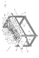
- a switcher for product supply lines comprising a frame 2 bearing a support and a rest plane 3 for the products.
- the rest plane 3 can be a conveyor belt which moves the products, or a fixed panel on which the products advance by being pushed by products situated behind, or it can be a roller table which by rotating cause the products to advance.
- the frame further comprises four legs 2a united inferiorly by four stiffening bars 2b. Superiorly a first transversal portion 4 and a second transversal portion 5, parallel to one another, each connect a pair of adjacent legs 2a.
- the first and the second transversal portions 4, 5 are constituted by straight elements.
- the second transversal portion 5 exhibits a side 5a, which is a more external side, which is arched, having a convexity thereof turned towards the outside of the frame 2.
- a self-bearing support element 6 is connected to the first transversal portion 4.
- the support element 6 is rotatably constrained, by an end thereof, to the first transversal portion 4 and rotates about a fixed axis 8 with respect to the frame 2.
- the fixed axis 8 is the hinge axis of a vertical pivot 9 which connects the support element 6 to the first transversal portion 4 of the frame 2.
- the support element 6 preferably exhibits a longitudinal axis 6a having a straight development.
- the second end 10 of the support element 6 exhibits rest means 11 by which the support element 6 is in contact with the second transversal portion 5 of the frame 2.
- the rest means 11 comprise at least a sliding system 12, such as for example a bearing system, with which the second end 10 of the support element 6 slides along the second transversal portion 5, in a circular trajectory.
- the guide channel 13 is constrained below the support element 6.
- the guide channel 13 exhibits a straight longitudinal axis development and is aligned with the overlying support element 6.
- a telescopic channel 15 is located at an end 14 of the guide channel 13.
- the telescopic channel 15 is a prolongation of the guide channel 13 and is thus located at the end 14 of the guide channel 13 further from the rotation axis 8.
- the telescopic channel 15 is located at the end 14 of the guide channel 13 opposite the product input end. Consequently the support element 6 is superposed and aligned to the telescopic channel 15 but is not rigidly connected thereto.
- the telescopic channel 15 is able to translate longitudinally with respect to the guide channel 13, running rigidly below the support element 6.
- the telescopic channel 15 can lengthen, accompanying the product up to its destination, preferably moving forward at the same speed thereas.
- the switcher 1 further comprises a first cursor 16 and a second 17 cursor, both located in contact with and above the support element 6.
- the first cursor 16 and the second cursor 17 are slidably mobile along the support element 6, powered by the means for movement.
- the means for movement comprise a linear motor; the support element 6, the first cursor 16 and the second cursor 17 constitute the linear motor.
- the support element 6 comprises a plurality of permanent magnets 18 aligned along the longitudinal development thereof and positioned on the upper surface thereof.
- a coil 19 is located internally of each cursor 16, 17, which coil 19 interacts with the permanent magnets 18 present on the support element 6.
- the permanent magnets 18 define a straight track 20 along which the coils 19, and therefore the cursors 16 and 17, run.
- the cursors 16 and 17 are longitudinally aligned along the support element 6 and, advantageously, the first cursor 16 is closer to the second end 10 of the support element 6, while the second cursor 17 is closer to the first end 7 of the support element 6.
- the telescopic channel 15 is constrained to the first cursor 16 which, sliding along the track 20 of permanent magnets 18, causes the translation of the telescopic channel 15.
- a con rod 21 is located by a side of the support element 6, which con rod 21 has a first end 22 hinged,by a pivot 23, to the first transversal portion 4 of the frame 2, and a second end 24 which is hinged to the second cursor 17.
- the con rod 21 is connected to an upper portion 17a of the second cursor 17, and the first end 22 and the second end 24 of the con rod 21 are situated at two different heights.
- the lateral profile of the con rod 21, therefore, exhibits two straight tracts 21a connected by an elbow 21b having a concavity facing the rest plane 3, as can be seen in figures 1 and 3.
- Figure 2 shows that the con rod 21, seen from above, is straight.
- the con rod 21 rotates about the hinge axis 23a of the pivot 23 connecting it to the frame 2.
- the con rod 21 has a longitudinal development which is smaller than the length of the support element 6 and, seen from above, is therefore inclined with respect to the longitudinal axis 6a of the support element 6.
- the sliding of the second cursor 17 along the tract 20 is limited by the length of the con rod 21. Therefore, as the second cursor 17 is maintained at a fixed distance from the frame 2 following connection with the con rod 21, the linear motion of the second cursor 17 along the track 20 is translated into a circular motion of the support element 6 about the hinge axis 8 of the pivot 9.
- the coil 19 of the second cursor 17, as it moves along the track 20 of permanent magnets 18, causes the linear motor, the guide channel 13 and the telescopic channel 15 to rotate about the hinge axis 8, laterally displacing the products which advance along the guide channel 13.
- the second cursor 17 describes a movement which is a composition of the straight motion along the track 20 and the circular motion about the hinge axis 23a about which the con rod 21 rotates.
- the movement of the two cursors 16 and 17 is synchronised so as to lengthen or retract the telescopic channel 15 in accordance with positions of the various output conduits, according to the angular position of the support element 6, i.e. the linear position of the first cursor 16 on the track 20.
- the means for actuating 25 generally comprise a pair of operation drives 26 in mutual communication by means of a flexible structure 27 and applied directly on the mobile parts of the linear motor, i.e. the two cursors 16 and 17.
- Each drive 26 comprises a panel 28 externally exhibiting means for electrical coupling, such as connectors 29, for externally interfacing the coils 19.
- each means for activating comprises an encoder, not illustrated, for commanding and controlling the movement and the position of the two coils 19.
- Each drive 26 is applied externally to a respective cursor 16, 17, on the upper surface or on one of the two lateral surfaces parallel to the axis 6a, according to need.
- the drives 26 are situated on the lateral surface of the cursors 16 and 17.
- Each cursor 16, 17 exhibits, on the lateral surfaces perpendicular to the longitudinal axis 6a of the guide element 6, at least an end-run element 30, for preventing impacts between the two cursors 16, 17 and between the two cursors 16, 17 and the structural parts located at the two ends 7 and 10 of the support element 6.
- the switcher for supply lines of the invention can alternatively be used inversely, removing products from several lines to entrain them towards a single output channel.
- the products in arrival are subdivided into several input conduits, and a removed by the telescopic channel 15, cross the guide channel 13 and reach a single output channel.
- the switcher device of the invention is generally mounted on lines that select products or which perform filling, packing or quality control operations on the product.
- the lines include a machine, not illustrated, for separating products generally comprising at least a product supply line, a plurality of output conduits and an a switcher device 1 according to what is described in the preferred embodiment located between the supply line and the output conduits.
- a machine for grouping products, which comprises a plurality of product supply lines, at least a product output line, and a switcher device 1 according to what is described in the alternative configuration (not illustrated) or functioning inversely, located between the product supply lines and the output conduit.
- a switcher for supply lines according to the present invention enables a considerable structural and applicational simplification of the whole device to be made.
- the smaller number of components also leads to an increase in MTBF, i.e. it improves the apparatus' reliability.
- the application of the direct linear motor obviates mechanical chains and uses only one con rod as a moving organ, thus offering important advantages, such as improvement in system performance, improved production and energy saving, as well as a reduction in apparatus noise levels.
- the special positioning of the mobile coils requires only a short cable tract which normally is made using chain cable or, preferably in order to reduce noise and mass further as well as increasing the compactness of the device, self-bearing cable ribbon for the flexible structure 27. It is therefore possible to obtain a considerable lightening of the cabling, using a solution which includes the possibility of connecting and directly managing the sensors by means of a pair of drives, operatively simpler and more precise, directly integrated on the mobile coils.
- the linear motor also achieves the double aim of controlled movement and self-bearing main mechanical structure, thus considerably simplifying the whole device which is very compact, and can be managed as if it were a single component.
- the rated and peak power of the linear motor combined with the transmission ratio of the con rod, enable high production values to be attained even where the masses to be moved are large.
Landscapes
- Engineering & Computer Science (AREA)
- Mechanical Engineering (AREA)
- Branching, Merging, And Special Transfer Between Conveyors (AREA)
- Linear Motors (AREA)
- Control Of Conveyors (AREA)
- Push-Button Switches (AREA)
- Discharge Of Articles From Conveyors (AREA)
Priority Applications (6)
| Application Number | Priority Date | Filing Date | Title |
|---|---|---|---|
| DE602006001195T DE602006001195D1 (de) | 2006-02-06 | 2006-02-06 | Weichenvorrichtung für eine Fördereinrichtung |
| EP06425061A EP1816093B1 (de) | 2006-02-06 | 2006-02-06 | Weichenvorrichtung für eine Fördereinrichtung |
| AT06425061T ATE395280T1 (de) | 2006-02-06 | 2006-02-06 | Weichenvorrichtung für eine fördereinrichtung |
| ES06425061T ES2306409T3 (es) | 2006-02-06 | 2006-02-06 | Desviador para un dispositivo transportador. |
| US11/657,977 US7461734B2 (en) | 2006-02-06 | 2007-01-25 | Switcher for product supply lines and a machine equipped with the switcher |
| CN200710006782XA CN101016119B (zh) | 2006-02-06 | 2007-02-06 | 用于产品供给线的转换器和配备有该转换器的机器 |
Applications Claiming Priority (1)
| Application Number | Priority Date | Filing Date | Title |
|---|---|---|---|
| EP06425061A EP1816093B1 (de) | 2006-02-06 | 2006-02-06 | Weichenvorrichtung für eine Fördereinrichtung |
Publications (2)
| Publication Number | Publication Date |
|---|---|
| EP1816093A1 true EP1816093A1 (de) | 2007-08-08 |
| EP1816093B1 EP1816093B1 (de) | 2008-05-14 |
Family
ID=36580482
Family Applications (1)
| Application Number | Title | Priority Date | Filing Date |
|---|---|---|---|
| EP06425061A Expired - Lifetime EP1816093B1 (de) | 2006-02-06 | 2006-02-06 | Weichenvorrichtung für eine Fördereinrichtung |
Country Status (6)
| Country | Link |
|---|---|
| US (1) | US7461734B2 (de) |
| EP (1) | EP1816093B1 (de) |
| CN (1) | CN101016119B (de) |
| AT (1) | ATE395280T1 (de) |
| DE (1) | DE602006001195D1 (de) |
| ES (1) | ES2306409T3 (de) |
Cited By (2)
| Publication number | Priority date | Publication date | Assignee | Title |
|---|---|---|---|---|
| EP1985558A1 (de) * | 2007-04-27 | 2008-10-29 | Mechatronic System Company S.r.l. | Schalter für Produktzufuhrleitungen |
| EP2704969A1 (de) | 2011-05-03 | 2014-03-12 | Tetra Laval Holdings & Finance S.A. | Teiler zur unterteilung von produkten in parallelreihen |
Families Citing this family (4)
| Publication number | Priority date | Publication date | Assignee | Title |
|---|---|---|---|---|
| CN102556640B (zh) * | 2012-02-08 | 2014-03-26 | 广东摩德娜科技股份有限公司 | 一种窑尾自动分类收砖机 |
| CN103818719B (zh) * | 2014-03-18 | 2015-12-02 | 湖北三丰驰众机器人有限公司 | 料架旋转自动上料装置 |
| US9783375B2 (en) * | 2014-08-12 | 2017-10-10 | Kaufman Engineered Systems, Inc. | Lane forming apparatus |
| EP3750403B1 (de) * | 2019-06-12 | 2023-08-02 | Radie B.V. | Vorrichtung zur ausrichtung von teigstücken |
Citations (3)
| Publication number | Priority date | Publication date | Assignee | Title |
|---|---|---|---|---|
| US3193078A (en) * | 1963-01-18 | 1965-07-06 | Emhart Corp | Article divider for conveyors |
| EP0480436A2 (de) * | 1990-10-11 | 1992-04-15 | Tetra Laval Holdings & Finance SA | Einrichtung zum Verteilen und Sammeln von zu fördernden Produkten |
| EP1245512A2 (de) * | 2001-03-30 | 2002-10-02 | Ronchiteck S.r.l. | Vorrichtung zum Greifen von in einer einzigen Reihe ankommenden Behältern und zum Verteilen von diesen Behältern auf mehrere parallele Transportwege |
Family Cites Families (7)
| Publication number | Priority date | Publication date | Assignee | Title |
|---|---|---|---|---|
| US4147248A (en) * | 1977-10-21 | 1979-04-03 | Mojonnier Bros. Co. | Dividing container conveyor |
| US4616745A (en) * | 1984-03-26 | 1986-10-14 | Hartness Robert G | Apparatus for aligning and feeding articles upright on an article loading machine |
| US4723649A (en) * | 1986-07-21 | 1988-02-09 | Hartness International | Apparatus for aligning articles in parallel rows |
| US5186306A (en) * | 1989-11-23 | 1993-02-16 | Tetra Alfa Holdings S.A. | Method and an apparatus for marshalling objects |
| US5944165A (en) * | 1995-05-02 | 1999-08-31 | Lever Brothers Company | Lane distribution apparatus |
| AU2003291228A1 (en) * | 2002-11-02 | 2004-06-07 | Ambec, Inc. | Apparatus for diverting successive articles in a single lane to plural lanes |
| US7114609B2 (en) * | 2005-02-08 | 2006-10-03 | Paper Converting Machine Company | Product diverter and method |
-
2006
- 2006-02-06 EP EP06425061A patent/EP1816093B1/de not_active Expired - Lifetime
- 2006-02-06 AT AT06425061T patent/ATE395280T1/de not_active IP Right Cessation
- 2006-02-06 ES ES06425061T patent/ES2306409T3/es not_active Expired - Lifetime
- 2006-02-06 DE DE602006001195T patent/DE602006001195D1/de not_active Expired - Lifetime
-
2007
- 2007-01-25 US US11/657,977 patent/US7461734B2/en active Active
- 2007-02-06 CN CN200710006782XA patent/CN101016119B/zh not_active Expired - Fee Related
Patent Citations (3)
| Publication number | Priority date | Publication date | Assignee | Title |
|---|---|---|---|---|
| US3193078A (en) * | 1963-01-18 | 1965-07-06 | Emhart Corp | Article divider for conveyors |
| EP0480436A2 (de) * | 1990-10-11 | 1992-04-15 | Tetra Laval Holdings & Finance SA | Einrichtung zum Verteilen und Sammeln von zu fördernden Produkten |
| EP1245512A2 (de) * | 2001-03-30 | 2002-10-02 | Ronchiteck S.r.l. | Vorrichtung zum Greifen von in einer einzigen Reihe ankommenden Behältern und zum Verteilen von diesen Behältern auf mehrere parallele Transportwege |
Cited By (3)
| Publication number | Priority date | Publication date | Assignee | Title |
|---|---|---|---|---|
| EP1985558A1 (de) * | 2007-04-27 | 2008-10-29 | Mechatronic System Company S.r.l. | Schalter für Produktzufuhrleitungen |
| US7658274B2 (en) | 2007-04-27 | 2010-02-09 | Motor Power Company S.R.L. | Switcher for product supply lines |
| EP2704969A1 (de) | 2011-05-03 | 2014-03-12 | Tetra Laval Holdings & Finance S.A. | Teiler zur unterteilung von produkten in parallelreihen |
Also Published As
| Publication number | Publication date |
|---|---|
| CN101016119B (zh) | 2012-05-02 |
| ES2306409T3 (es) | 2008-11-01 |
| EP1816093B1 (de) | 2008-05-14 |
| US20070181401A1 (en) | 2007-08-09 |
| DE602006001195D1 (de) | 2008-06-26 |
| CN101016119A (zh) | 2007-08-15 |
| ATE395280T1 (de) | 2008-05-15 |
| US7461734B2 (en) | 2008-12-09 |
Similar Documents
| Publication | Publication Date | Title |
|---|---|---|
| EP1985558B1 (de) | Schalter für Produktzufuhrleitungen | |
| US7461734B2 (en) | Switcher for product supply lines and a machine equipped with the switcher | |
| RU2702367C2 (ru) | Транспортирующее устройство и способ транспортировки с помощью такого транспортирующего устройства | |
| EP3085646B1 (de) | Vorrichtung zur zuführung von produkten und zum umstossen davon in einer einzugslinie | |
| EP2704969B1 (de) | Teiler zur unterteilung von produkten in parallelreihen | |
| US20150027852A1 (en) | Device and method for discharging products, particularly product containers such as bottles | |
| US6508153B1 (en) | Conveyor product transfer apparatus and method | |
| US8616361B1 (en) | Diverter assembly | |
| JP2010505712A (ja) | ダンボール箱用ブランクを搬送するための機械 | |
| US20150283596A1 (en) | Workpiece conveying device | |
| CN108482966A (zh) | 一种用于积放式悬挂输送机的助推装置 | |
| CN105416669B (zh) | 一种分道装置 | |
| CN213893040U (zh) | 一种换向机构及面包包装机 | |
| CN110171673A (zh) | 包装装置、输送设备和用于输送设备的推车组件 | |
| EP1710162B1 (de) | Verpackungsmaschine mit simulierten Nocken | |
| CN214875904U (zh) | 一种乳膏制品连续送药装置 | |
| KR20130121882A (ko) | 장치, 이 장치의 작동 방법 및 장치에서 사용하기 위한 공구 | |
| CN224014037U (zh) | 一种包装盒推料输送机构 | |
| CN205221213U (zh) | 一种分道装置 | |
| CN222022956U (zh) | 一种棉纺纱加工打包装置 | |
| CN116835068B (zh) | 一种筒纱包装袋快速交互装置 | |
| CN110239928A (zh) | 一种智能带输送分道机 | |
| CN210456349U (zh) | 一种托板推送机 | |
| CN117902252A (zh) | 一种一体式行走梁 | |
| JP2000320636A (ja) | 直線運動機構及び搬送装置 |
Legal Events
| Date | Code | Title | Description |
|---|---|---|---|
| PUAI | Public reference made under article 153(3) epc to a published international application that has entered the european phase |
Free format text: ORIGINAL CODE: 0009012 |
|
| AK | Designated contracting states |
Kind code of ref document: A1 Designated state(s): AT BE BG CH CY CZ DE DK EE ES FI FR GB GR HU IE IS IT LI LT LU LV MC NL PL PT RO SE SI SK TR |
|
| AX | Request for extension of the european patent |
Extension state: AL BA HR MK YU |
|
| 17P | Request for examination filed |
Effective date: 20070830 |
|
| GRAP | Despatch of communication of intention to grant a patent |
Free format text: ORIGINAL CODE: EPIDOSNIGR1 |
|
| RIN1 | Information on inventor provided before grant (corrected) |
Inventor name: MIGNANO, PAOLO |
|
| GRAS | Grant fee paid |
Free format text: ORIGINAL CODE: EPIDOSNIGR3 |
|
| GRAA | (expected) grant |
Free format text: ORIGINAL CODE: 0009210 |
|
| AKX | Designation fees paid |
Designated state(s): AT BE BG CH CY CZ DE DK EE ES FI FR GB GR HU IE IS IT LI LT LU LV MC NL PL PT RO SE SI SK TR |
|
| AK | Designated contracting states |
Kind code of ref document: B1 Designated state(s): AT BE BG CH CY CZ DE DK EE ES FI FR GB GR HU IE IS IT LI LT LU LV MC NL PL PT RO SE SI SK TR |
|
| REG | Reference to a national code |
Ref country code: GB Ref legal event code: FG4D |
|
| REG | Reference to a national code |
Ref country code: CH Ref legal event code: EP |
|
| REG | Reference to a national code |
Ref country code: IE Ref legal event code: FG4D Free format text: LANGUAGE OF EP DOCUMENT: FRENCH |
|
| REF | Corresponds to: |
Ref document number: 602006001195 Country of ref document: DE Date of ref document: 20080626 Kind code of ref document: P |
|
| PG25 | Lapsed in a contracting state [announced via postgrant information from national office to epo] |
Ref country code: SI Free format text: LAPSE BECAUSE OF FAILURE TO SUBMIT A TRANSLATION OF THE DESCRIPTION OR TO PAY THE FEE WITHIN THE PRESCRIBED TIME-LIMIT Effective date: 20080514 |
|
| PG25 | Lapsed in a contracting state [announced via postgrant information from national office to epo] |
Ref country code: FI Free format text: LAPSE BECAUSE OF FAILURE TO SUBMIT A TRANSLATION OF THE DESCRIPTION OR TO PAY THE FEE WITHIN THE PRESCRIBED TIME-LIMIT Effective date: 20080514 |
|
| REG | Reference to a national code |
Ref country code: ES Ref legal event code: FG2A Ref document number: 2306409 Country of ref document: ES Kind code of ref document: T3 |
|
| NLV1 | Nl: lapsed or annulled due to failure to fulfill the requirements of art. 29p and 29m of the patents act | ||
| PG25 | Lapsed in a contracting state [announced via postgrant information from national office to epo] |
Ref country code: PL Free format text: LAPSE BECAUSE OF FAILURE TO SUBMIT A TRANSLATION OF THE DESCRIPTION OR TO PAY THE FEE WITHIN THE PRESCRIBED TIME-LIMIT Effective date: 20080514 Ref country code: LV Free format text: LAPSE BECAUSE OF FAILURE TO SUBMIT A TRANSLATION OF THE DESCRIPTION OR TO PAY THE FEE WITHIN THE PRESCRIBED TIME-LIMIT Effective date: 20080514 Ref country code: AT Free format text: LAPSE BECAUSE OF FAILURE TO SUBMIT A TRANSLATION OF THE DESCRIPTION OR TO PAY THE FEE WITHIN THE PRESCRIBED TIME-LIMIT Effective date: 20080514 Ref country code: NL Free format text: LAPSE BECAUSE OF FAILURE TO SUBMIT A TRANSLATION OF THE DESCRIPTION OR TO PAY THE FEE WITHIN THE PRESCRIBED TIME-LIMIT Effective date: 20080514 |
|
| PG25 | Lapsed in a contracting state [announced via postgrant information from national office to epo] |
Ref country code: IS Free format text: LAPSE BECAUSE OF FAILURE TO SUBMIT A TRANSLATION OF THE DESCRIPTION OR TO PAY THE FEE WITHIN THE PRESCRIBED TIME-LIMIT Effective date: 20080914 |
|
| PG25 | Lapsed in a contracting state [announced via postgrant information from national office to epo] |
Ref country code: LT Free format text: LAPSE BECAUSE OF FAILURE TO SUBMIT A TRANSLATION OF THE DESCRIPTION OR TO PAY THE FEE WITHIN THE PRESCRIBED TIME-LIMIT Effective date: 20080514 Ref country code: DK Free format text: LAPSE BECAUSE OF FAILURE TO SUBMIT A TRANSLATION OF THE DESCRIPTION OR TO PAY THE FEE WITHIN THE PRESCRIBED TIME-LIMIT Effective date: 20080514 Ref country code: CZ Free format text: LAPSE BECAUSE OF FAILURE TO SUBMIT A TRANSLATION OF THE DESCRIPTION OR TO PAY THE FEE WITHIN THE PRESCRIBED TIME-LIMIT Effective date: 20080514 Ref country code: SE Free format text: LAPSE BECAUSE OF FAILURE TO SUBMIT A TRANSLATION OF THE DESCRIPTION OR TO PAY THE FEE WITHIN THE PRESCRIBED TIME-LIMIT Effective date: 20080814 |
|
| PG25 | Lapsed in a contracting state [announced via postgrant information from national office to epo] |
Ref country code: SK Free format text: LAPSE BECAUSE OF FAILURE TO SUBMIT A TRANSLATION OF THE DESCRIPTION OR TO PAY THE FEE WITHIN THE PRESCRIBED TIME-LIMIT Effective date: 20080514 Ref country code: BE Free format text: LAPSE BECAUSE OF FAILURE TO SUBMIT A TRANSLATION OF THE DESCRIPTION OR TO PAY THE FEE WITHIN THE PRESCRIBED TIME-LIMIT Effective date: 20080514 Ref country code: PT Free format text: LAPSE BECAUSE OF FAILURE TO SUBMIT A TRANSLATION OF THE DESCRIPTION OR TO PAY THE FEE WITHIN THE PRESCRIBED TIME-LIMIT Effective date: 20081014 Ref country code: RO Free format text: LAPSE BECAUSE OF FAILURE TO SUBMIT A TRANSLATION OF THE DESCRIPTION OR TO PAY THE FEE WITHIN THE PRESCRIBED TIME-LIMIT Effective date: 20080514 |
|
| PLBE | No opposition filed within time limit |
Free format text: ORIGINAL CODE: 0009261 |
|
| STAA | Information on the status of an ep patent application or granted ep patent |
Free format text: STATUS: NO OPPOSITION FILED WITHIN TIME LIMIT |
|
| 26N | No opposition filed |
Effective date: 20090217 |
|
| PG25 | Lapsed in a contracting state [announced via postgrant information from national office to epo] |
Ref country code: EE Free format text: LAPSE BECAUSE OF FAILURE TO SUBMIT A TRANSLATION OF THE DESCRIPTION OR TO PAY THE FEE WITHIN THE PRESCRIBED TIME-LIMIT Effective date: 20080514 Ref country code: BG Free format text: LAPSE BECAUSE OF FAILURE TO SUBMIT A TRANSLATION OF THE DESCRIPTION OR TO PAY THE FEE WITHIN THE PRESCRIBED TIME-LIMIT Effective date: 20080814 |
|
| PG25 | Lapsed in a contracting state [announced via postgrant information from national office to epo] |
Ref country code: MC Free format text: LAPSE BECAUSE OF NON-PAYMENT OF DUE FEES Effective date: 20090228 |
|
| REG | Reference to a national code |
Ref country code: IE Ref legal event code: MM4A |
|
| PG25 | Lapsed in a contracting state [announced via postgrant information from national office to epo] |
Ref country code: IE Free format text: LAPSE BECAUSE OF NON-PAYMENT OF DUE FEES Effective date: 20090206 |
|
| REG | Reference to a national code |
Ref country code: CH Ref legal event code: PL |
|
| PG25 | Lapsed in a contracting state [announced via postgrant information from national office to epo] |
Ref country code: GR Free format text: LAPSE BECAUSE OF FAILURE TO SUBMIT A TRANSLATION OF THE DESCRIPTION OR TO PAY THE FEE WITHIN THE PRESCRIBED TIME-LIMIT Effective date: 20080815 Ref country code: CH Free format text: LAPSE BECAUSE OF NON-PAYMENT OF DUE FEES Effective date: 20100228 Ref country code: LI Free format text: LAPSE BECAUSE OF NON-PAYMENT OF DUE FEES Effective date: 20100228 |
|
| PG25 | Lapsed in a contracting state [announced via postgrant information from national office to epo] |
Ref country code: LU Free format text: LAPSE BECAUSE OF NON-PAYMENT OF DUE FEES Effective date: 20090206 |
|
| PGFP | Annual fee paid to national office [announced via postgrant information from national office to epo] |
Ref country code: FR Payment date: 20110314 Year of fee payment: 6 |
|
| PG25 | Lapsed in a contracting state [announced via postgrant information from national office to epo] |
Ref country code: HU Free format text: LAPSE BECAUSE OF FAILURE TO SUBMIT A TRANSLATION OF THE DESCRIPTION OR TO PAY THE FEE WITHIN THE PRESCRIBED TIME-LIMIT Effective date: 20081115 |
|
| PGFP | Annual fee paid to national office [announced via postgrant information from national office to epo] |
Ref country code: GB Payment date: 20110228 Year of fee payment: 6 Ref country code: ES Payment date: 20110322 Year of fee payment: 6 |
|
| PG25 | Lapsed in a contracting state [announced via postgrant information from national office to epo] |
Ref country code: TR Free format text: LAPSE BECAUSE OF FAILURE TO SUBMIT A TRANSLATION OF THE DESCRIPTION OR TO PAY THE FEE WITHIN THE PRESCRIBED TIME-LIMIT Effective date: 20080514 |
|
| PG25 | Lapsed in a contracting state [announced via postgrant information from national office to epo] |
Ref country code: CY Free format text: LAPSE BECAUSE OF FAILURE TO SUBMIT A TRANSLATION OF THE DESCRIPTION OR TO PAY THE FEE WITHIN THE PRESCRIBED TIME-LIMIT Effective date: 20080514 |
|
| GBPC | Gb: european patent ceased through non-payment of renewal fee |
Effective date: 20120206 |
|
| REG | Reference to a national code |
Ref country code: FR Ref legal event code: ST Effective date: 20121031 |
|
| PG25 | Lapsed in a contracting state [announced via postgrant information from national office to epo] |
Ref country code: GB Free format text: LAPSE BECAUSE OF NON-PAYMENT OF DUE FEES Effective date: 20120206 Ref country code: FR Free format text: LAPSE BECAUSE OF NON-PAYMENT OF DUE FEES Effective date: 20120229 |
|
| REG | Reference to a national code |
Ref country code: ES Ref legal event code: FD2A Effective date: 20130708 |
|
| PG25 | Lapsed in a contracting state [announced via postgrant information from national office to epo] |
Ref country code: ES Free format text: LAPSE BECAUSE OF NON-PAYMENT OF DUE FEES Effective date: 20120207 |
|
| PGFP | Annual fee paid to national office [announced via postgrant information from national office to epo] |
Ref country code: IT Payment date: 20230227 Year of fee payment: 18 Ref country code: DE Payment date: 20230227 Year of fee payment: 18 |
|
| REG | Reference to a national code |
Ref country code: DE Ref legal event code: R119 Ref document number: 602006001195 Country of ref document: DE |
|
| PG25 | Lapsed in a contracting state [announced via postgrant information from national office to epo] |
Ref country code: DE Free format text: LAPSE BECAUSE OF NON-PAYMENT OF DUE FEES Effective date: 20240903 |
|
| PG25 | Lapsed in a contracting state [announced via postgrant information from national office to epo] |
Ref country code: DE Free format text: LAPSE BECAUSE OF NON-PAYMENT OF DUE FEES Effective date: 20240903 |
|
| PG25 | Lapsed in a contracting state [announced via postgrant information from national office to epo] |
Ref country code: IT Free format text: LAPSE BECAUSE OF NON-PAYMENT OF DUE FEES Effective date: 20240206 |