EP1816097A2 - Dispositifs pour préparer une bobine formée d'une bande de matériau enroulé pour un changement automatique de bobine - Google Patents
Dispositifs pour préparer une bobine formée d'une bande de matériau enroulé pour un changement automatique de bobine Download PDFInfo
- Publication number
- EP1816097A2 EP1816097A2 EP07107657A EP07107657A EP1816097A2 EP 1816097 A2 EP1816097 A2 EP 1816097A2 EP 07107657 A EP07107657 A EP 07107657A EP 07107657 A EP07107657 A EP 07107657A EP 1816097 A2 EP1816097 A2 EP 1816097A2
- Authority
- EP
- European Patent Office
- Prior art keywords
- adhesive tape
- cutting
- dispensing device
- web
- material web
- Prior art date
- Legal status (The legal status is an assumption and is not a legal conclusion. Google has not performed a legal analysis and makes no representation as to the accuracy of the status listed.)
- Granted
Links
Images




Classifications
-
- B—PERFORMING OPERATIONS; TRANSPORTING
- B65—CONVEYING; PACKING; STORING; HANDLING THIN OR FILAMENTARY MATERIAL
- B65H—HANDLING THIN OR FILAMENTARY MATERIAL, e.g. SHEETS, WEBS, CABLES
- B65H19/00—Changing the web roll
- B65H19/10—Changing the web roll in unwinding mechanisms or in connection with unwinding operations
- B65H19/102—Preparing the leading end of the replacement web before splicing operation; Adhesive arrangements on leading end of replacement web; Tabs and adhesive tapes for splicing
-
- B—PERFORMING OPERATIONS; TRANSPORTING
- B65—CONVEYING; PACKING; STORING; HANDLING THIN OR FILAMENTARY MATERIAL
- B65H—HANDLING THIN OR FILAMENTARY MATERIAL, e.g. SHEETS, WEBS, CABLES
- B65H19/00—Changing the web roll
- B65H19/10—Changing the web roll in unwinding mechanisms or in connection with unwinding operations
- B65H19/18—Attaching, e.g. pasting, the replacement web to the expiring web
- B65H19/1805—Flying splicing, i.e. the expiring web moving during splicing contact
Definitions
- the invention relates to devices for preparing a wound from a material web supply roll for a flying reel change according to the preamble of claim 1, 14, 25, 27 and 31st
- the WO 03/057605 A1 discloses a device for preparing a flying reel change, in which a device for applying adhesive tape is controlled by means of a sensor of the edge of the supply roll.
- the EP 0 640 545 A1 describes a device for applying adhesive tape to a supply roll, in which the pressure roller of the adhesive tape is driven by means of a motor.
- the DE 101 39 563 A1 the DE 696 16 892 T2 and the EP 771 300 B1 are Devices for applying adhesive tape known.
- the invention has for its object to provide devices for preparing a wound from a web supply roll for a flying role change.
- the device in each case an outer edge of the wound up on the supply roll material web, for. B. paper web short path newly created, and by the movement of the adhesive tape dispensing device, an adhesive tape is applied in an exactly the length of this edge length corresponding to the thus generated edge of the web.
- Cutting device and adhesive tape dispensing device of the device are preferably mounted together on a carriage. This makes it possible to cut the edge on a single reciprocation of the carriage during a first crossing of the web and to apply the adhesive tape in the subsequent crossing in the opposite direction.
- the adhesive tape dispensing device preferably has a roller for conveying the adhesive tape, the rotational speed of which is coupled to the movement speed of the adhesive tape dispensing device on its path across the web. This coupling prevents the adhesive tape from passing from the dispenser to the web is exposed to uncontrolled tensile forces that can lead to tearing of the adhesive tape.
- the tape-dispensing device is provided with at least one tensioning tool for tensioning the web in its longitudinal direction.
- the clamping tool is preferably arranged in front of an element which presses the adhesive tape onto the material web.
- the clamping tool is preferably formed by a rolling on the web tensioning roller whose axis forms a non-right angle with the direction of movement of the adhesive tape dispensing device, so that upon movement of the tensioning roller in the direction of movement exerts this perpendicular to the direction of force on the web.
- the direction of movement of the cutting device and the adhesive tape dispensing device can be defined perpendicular to the longitudinal edge of the web to be prepared.
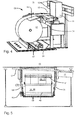
- Fig. 1 shows an independent device for carrying out the preparation for a flying reel change according to the invention.
- a supply roll 01 here a paper web roll 01
- the unpacked paper web roll 01 is oriented so that the free end of the material web, for. B. paper web on the device 05 facing side of the paper web roll 01 freely suspended.
- a lifting device 04 is inserted, which is shown in Fig. 1 in retracted position and two liftable and rotatably driven rollers 47 includes, which, when raised, with a preparation position in front of the device 05th located paper web roll 01 come into contact and can put them in rotation.
- the width of the work table 06 corresponds at least to the web width of the paper web wound on the paper web roll 01.
- the device 05 has two arms 08 which are pivotable about an axis 07 and which at their free end and around this free end are pivotably held about an axis parallel to the axis 07, carry two rubber rollers 09 and a brush roller 49.
- the rubber rollers 09 are mutually displaceable and can be brought into frictional contact with each other, so that one of them, which is driven by a motor 56 shown in Fig. 5, the other entrains.
- the arms 08 are lowered toward the paper web roll 01 held on the lifting device 04 until, in the position shown in FIG. 2, a reed contact or an equivalent sensor indicates that the rubber rollers 09 are the one Touch paper web roll 01. Then, the contacting rubber rollers 09 are rotated by the motor 56 in rotation. At the same time, the rollers 47 of the lifter 04 are rotated so that paper from both sides of the position where the rubber rollers 09 contact the paper web is drawn into the gap between the two rubber rollers 09 and pinched therein.
- the arms 08 pivot back out of the position of FIG. 2 and back beyond the initial position of FIG. 1 and the intermediate position of FIG. 3 to the position shown in FIG. 4, accompanied by a corresponding rotation of the Rolls 47 of the lifting device 04, further paper unwound from the paper web roll 01 and spread on the work table 06.
- the rails 12 are arranged in a horizontal plane at a small angle, preferably in an opening angle of greater than 1 ° smaller than 10 °, in particular of 3 ° + / 1.5 ° to the longitudinal axis of the paper web roll 01, so that the cutting and adhesive tape dispensing device 11 slightly moved obliquely over the spread on the horizontal portion 13 of the work table 06 piece of paper web. But it is also a parallel course of the rails 12 possible and / or the inclination of the rail 12 is adjustable.
- FIG. 5 shows this with reference to a plan view of the device 05 with arms 08 held in the position of FIG. 1.
- a cutting edge 51 extends parallel to the alignment of the rails 12 along an edge of the region 13 facing away from the paper web roll 01.
- Fig. 6 shows schematically the structure of the cutting and tape dispensing device 11. It comprises an adhesive tape dispensing device 14, for. Example, an adhesive tape dispenser 14, the structure of which is explained in more detail with reference to FIG. 7, and / or preferably a reflective foil dispenser 16 and a cutting device with a held on an articulated arm 18, circular cutting blade 17, which by means of an actuating cylinder 19 from the illustrated retracted position is lowered into a cutting position in which it intersects the cutting edge 51 of the work table 06.
- a second actuating cylinder is provided with a direction of action perpendicular to the plane of FIG. 6 in order to press the cutting blade 17 in its lowered position against the cutting edge 51 of the work table 06.
- a clamping finger 21 which is shown in Fig. 1 from the rear portion 13 of the work table 06 in the vicinity of the cutting edge 51 upwardly projecting, pivoted down to a lateral edge of the tail of the paper web to this against the work table 06th to press and fix so.
- the cutting and tape dispensing device 11 moves on the rails 12 at a first, high speed.
- a sensor 22 arranged adjacent to the cutting blade 17, for example an optical sensor or a reed contact detects when it, coming from the front in the perspective of FIG. 1, crosses the front edge 23 of the work table 06 and then triggers the actuation of the actuating cylinder 19 out, so that the cutting blade 17 is extended.
- the second actuating cylinder is activated to the cutting blade 17 to the cutting edge 51st to press.
- two sensors 24; 26, z. B. two web edge sensors 24; 26 here Reflexfotozellen, provided for detecting the edges of the paper web during the movement of the cutting and tape dispensing device 11.
- the sensor 24 detects the right edge of the paper web and causes a reduction in the speed of movement of the paper web Cutting and tape dispensing device 11, so that the sensor 26 crosses the edge in question at a lower speed.
- the sensor 26 When the sensor 26 detects this right edge, it activates another sensor 27 which is aligned with a scale attached to one of the rails 12 that carries position coding, such as a Gray code. By reading the relevant code at the time the second sensor 26 detects the right web edge, the sensor 27 is able to accurately measure the position of the right web edge.
- position coding such as a Gray code
- the cutting and tape dispensing device 11 is again accelerated to the high first speed, and the cutting knife 17 rapidly cuts through the paper web until the sensor 24 detects the crossing of the left web edge. Again, the speed of the cutting and tape dispensing device 11 is reduced to accurately measure the position of the left web edge with the aid of the second web edge-oriented sensor 26 and the scale-oriented sensor 27.
- the cutting and tape dispensing device 11 continues until the left end position of the guide has been reached and thus the left edge of the worktable 06 has passed; now the cutting blade 17 is raised again and the movement of the cutting and tape dispensing device 11 is stopped.
- a path of the adhesive tape 29 and the shroud 30 extends from the supply roll 28 initially via a plurality of pulleys 31 to a braking device 32 and from there in turn via pulleys 31 to a vertically movable pressure roller 33.
- the braking device 32 comprises a stationary and one with the aid of an actuating cylinder movable brake shoes 35, between which adhesive and shroud 29; 30 are passed.
- a belt tensioner is arranged in the form of a on a pivot arm 52 by means of an actuating cylinder 53 against the shroud 30 acted upon roller 54.
- the pressure roller 33 is lowered by adjusting cylinder (not shown) to press them along the previously cut by the cutting blade 17 on the edge held on the work table 06 paper web. Since the adhesive tape 29 adheres more strongly to the paper web than to the shroud 30, shroud 30 and adhesive tape 29 separate at this point, and the path of the shroud 30 continues to a collecting device 34, for. B. a take-up reel 34 on which the shroud 30 collects.
- Adhesive tape 29 and shroud 30 are conveyed by means of a drive roller 37 which, between the pressure roller 33 and the take-up reel 34, is looped around only by the shroud 30.
- the drive roller 37 is rotatably driven by a motor 36 (see FIG. 8) which rotates only when the pressure roller 33 is lowered against a paper web and whose rotational speed is exactly proportional to Movement speed of the cutting and adhesive tape dispensing device 11 is controlled so that the peripheral speed of the drive roller 37 coincides with the movement speed. This can be z. B. be carried out with a speed feedback. Thus, a tensile stress of the paper web during gluing, which could lead to undesirable slippage, avoided.
- the take-up reel 34 is slippable, for example, via a belt, coupled to the motor 36, so that the shroud 30 is always wound at the speed determined by the pressure roller 33.
- clamping tools 38, z. B. a roller 38, z. B. a tension roller 38 and a Hilfsandrückrolle 39 is provided which are movable by means of adjusting cylinders 41 between a raised position and a lowered position in which they press against the paper web or the work table 06.
- Fig. 8 shows a view of the tape dispenser 14 from below.
- the above-described components 28, 31, 32, 33, 34, 36, 49 and 41 are held.
- this base 42 moves exactly parallel to the cutting edge, with the various rolls partially over that part of the web that remains on the paper web roll 01, and partially over the cut Part.
- the motor 36 is above the cut part.
- the course of the cutting edge 51 is indicated as a dot-dash line.
- the axis of the tension roller 38 is not aligned exactly perpendicular to the base plate 42 and to the direction of movement of the cutting and adhesive dispensing device 11, but it deviates slightly from the vertical so that they the axis of the auxiliary pressing roller 39 on the paper web roll 01 facing side of the base plate 42 crosses.
- This inclination of the tension roller 38 is achieved that when the Cutting and adhesive tape dispensing device 11 from the left to the right relative to the perspective of Figs. 6 and 7, ie with the tension roller 38 ahead, moved across the paper web, the tension roller 38 on this paper web exerts a clamping force in the direction of the cutting edge 51 out.
- the web edge is always taut and can not beat waves when the tape dispenser 14 moves across it.
- a cutting tool 43, z. B. a cutting blade 43 is pivotally supported on a pivot arm 44 by a control cylinder 46. It serves to sever the adhesive tape 29 in each case after the completion of an adhesive tape dispensing operation. In order to exclude that the cutting blade 43 thereby damage the paper web, the cutting blade 43 is suspended so that it moves at a small angle ⁇ to the direction of movement B of the cutting and adhesive tape dispensing device 11.
- the tape dispensing process proceeds as follows. After the cutting and tape dispensing device 11 moves from right to left on the work table 06 and thereby cut off the paper web, it is now moved back, the sensor 27, the location of the cutting and tape dispensing device 11, z. B. based on the scale, continuously monitored. (Instead of the scale, a rotary encoder coupled to the drive is also possible.) For example, only the pulses of a stepping motor can be detected).
- Detected 27 calculated position at which the pressure roller 33 is located exactly over the left edge of the paper web, the pressure roller 33, tensioning roller 38 and auxiliary pressure roller 39 are lowered and the motor 36 is put into operation, so that adhesive tape 29 at the speed of the cutting and Tape dispensing device 11 is unwound and pressed onto the edge of the paper web, wherein the lying between the tensioning roller 38 and the auxiliary pressing roller 39 portion of the web edge is tightened as described above.
- the pressure roller 33 is raised again. Simultaneously with the lifting of the pressure roller 33, the braking device 32 begins to clamp shroud 30 and tape 29 so as to tighten the now freely extending between the right edge of the paper web and the raised pressure roller 33 piece of adhesive tape. Subsequently, the cutting blade 43 moves down to sever the tape 29 exactly at the level of the web edge. Only then does it come to a firm clamping on the braking device 32, and the promotion of the adhesive tape 29 by the motor 36 is stopped.
- the roller 54 of the belt tensioner is moved against the adhesive tape 29 in order to tension the cover tape 30 so that the beginning of the adhesive tape 29 comes to rest for the next bonding process at the location on the periphery of the pressure roller 33, which touches the paper web to be bonded.
- the adjusting cylinder 46; 53 which drive the movement of the cutting blade 43 as well as the braking device 32, are provided with a throttle, which slows the movement of both, in the case of the cutting blade 43, to prevent them in spite of the small angle in which they relate moved onto the paper web, it hangs on this and it breaks through, in the case of the braking device 32 to synchronize the braking operation with the cutting of the adhesive tape 29 so that the braking device 32 already tightens the tape 29 when the cutting blade 43 hits it, however, it does not completely stop, which, as the entire cutting and tape dispensing device 11 continues to move, would result in the tearing of the adhesive tape 29 at an uncontrollable location.
- Both throttles are adjustable in order, if necessary, to be able to adapt the speeds of the braking device 32 and the cutting blade 43 to each other.
- the cutting and adhesive tape dispensing device 11 moves further at the high first speed into its basic position shown in FIG.
- the arms 08 which carry the rubber rollers 09 and brush roller 49, pivoted back into the position of FIG. 2, in which they rest on the circumference of the paper web roll 01.
- the rollers 47 of the lifting device 04 are set in motion to rotate the paper web roll 01 in the counterclockwise direction, so that the paper web end is pulled down from the work table 06 and back to the paper web roll 01, while - either in or against the direction of the paper web end on the Worktable 06 rotating brush roller 49 presses the paper web against the body of the paper web roll 01 and so finally presses a projecting beyond the cut edge of the paper out portion of the adhesive tape 29 against the body of the paper web roll 01.
- the free end of the paper web is fixed on the supply roll body until it is withdrawn for use.
- the lifting table 04 is lowered again, so that the paper web roll 01 again comes to rest on the carriage 03, the carriage 03 is continued on the rail 02, and the arms 08 return to their in Fig. 1st shown starting position back.
- the device 05 is now ready to prepare a second supply roll in the manner described above.
- FIG. 9 shows, in a view analogous to FIG. 7, a second embodiment of an adhesive tape dispensing device 14. Parts of this adhesive tape dispensing device 14 which correspond to those of the adhesive tape dispensing device 14 of FIG. 7 are designated by the same reference numerals and will not be described again.
- the drive roller 37 is omitted in the embodiment of FIG. 9. Instead, the motor 36 is slippage coupled via a belt to the take-up reel 34, so that the shroud 30 is always wound with an adjustable lead to the speed of the pressure roller 33. This contributes to the fact that z. B. loops, which may arise due to the alternating curvatures between shroud 30 and tape 29 as they pass through the adhesive dispenser 14, are pulled taut, so that they can not interfere with the cutting of the adhesive tape 29.
- FIG. 10 shows, again in a view analogous to FIG. 7, a third embodiment of an adhesive tape dispensing device 14.
- the drive roller 37 driven by the motor 36 acts on the shroud 30 separated from the adhesive tape 29 behind the belt Pressure roller 33 a.
- the shroud 30 is not looped at a large angle to the drive roller 37 around, but runs with a small loop through a gap formed between the drive roller 37 and a rubber press roller 58, which is held pressed by a control cylinder 59 against the drive roller 37 is.
- a collecting device 61 e.g. B. a collecting container 61 which is provided to receive the unrolled shroud 30 during the movement of the adhesive tape dispenser 14.
- a cutting device 62 is arranged with a movable knife, which serves to chop the introduced into the collecting container 61 shroud 30 into short pieces, which are collected in the collecting container 61.
- the cutting device 62 is activated only once in each case after each tape dispensing operation in order to cut off the shroud 30 collected during this process in the collecting container 61.
- An actuator cylinder 64 is coupled to a shutter 63 of the reservoir 61 to open each of them when the carriage is in its left end position so as to dispense the collected shroud 30 into a stationary container (not shown).
- a blower not shown in FIG. 10, may be mounted on the collecting container 61 in order to discharge its contents into the stationary container. A renewed movement of the carriage is only started after the collecting container 61 emptied and its shutter 63 is closed again.
Landscapes
- Replacement Of Web Rolls (AREA)
- Adhesive Tape Dispensing Devices (AREA)
Applications Claiming Priority (3)
| Application Number | Priority Date | Filing Date | Title |
|---|---|---|---|
| DE102004008418 | 2004-02-19 | ||
| DE102004021623A DE102004021623A1 (de) | 2004-02-19 | 2004-05-03 | Vorrichtungen zum Vorbereiten einer Vorratsrolle für einen fliegenden Rollenwechsel und eine Klebebandspendeeinrichtung |
| EP05716734A EP1727755B1 (fr) | 2004-02-19 | 2005-02-18 | Dispositifs pour preparer une bobine formee d'une bande de materiau enroulee, pour changement de bobine automatique |
Related Parent Applications (1)
| Application Number | Title | Priority Date | Filing Date |
|---|---|---|---|
| EP05716734A Division EP1727755B1 (fr) | 2004-02-19 | 2005-02-18 | Dispositifs pour preparer une bobine formee d'une bande de materiau enroulee, pour changement de bobine automatique |
Publications (3)
| Publication Number | Publication Date |
|---|---|
| EP1816097A2 true EP1816097A2 (fr) | 2007-08-08 |
| EP1816097A3 EP1816097A3 (fr) | 2008-06-11 |
| EP1816097B1 EP1816097B1 (fr) | 2008-12-24 |
Family
ID=40176220
Family Applications (2)
| Application Number | Title | Priority Date | Filing Date |
|---|---|---|---|
| EP07107657A Expired - Lifetime EP1816097B1 (fr) | 2004-02-19 | 2005-02-18 | Dispositifs pour préparer une bobine formée d'une bande de matériau enroulé pour un changement automatique de bobine |
| EP06120107A Withdrawn EP1741649A3 (fr) | 2004-02-19 | 2005-02-18 | Dispositif pour préparer un rouleau de matière en bande pour un changement de rouleau en marche |
Family Applications After (1)
| Application Number | Title | Priority Date | Filing Date |
|---|---|---|---|
| EP06120107A Withdrawn EP1741649A3 (fr) | 2004-02-19 | 2005-02-18 | Dispositif pour préparer un rouleau de matière en bande pour un changement de rouleau en marche |
Country Status (3)
| Country | Link |
|---|---|
| EP (2) | EP1816097B1 (fr) |
| AT (1) | ATE418516T1 (fr) |
| DE (1) | DE502005006344D1 (fr) |
Families Citing this family (1)
| Publication number | Priority date | Publication date | Assignee | Title |
|---|---|---|---|---|
| CN110304481B (zh) * | 2019-07-22 | 2024-01-05 | 黄山富田精工智造股份有限公司 | 自动贴胶装置 |
Citations (5)
| Publication number | Priority date | Publication date | Assignee | Title |
|---|---|---|---|---|
| EP0640545A1 (fr) | 1993-08-27 | 1995-03-01 | Minnesota Mining And Manufacturing Company | Appareil et procédé pour appliquer une bande adhésive |
| EP0771300B1 (fr) | 1994-07-20 | 1998-11-18 | KOENIG & BAUER-ALBERT AKTIENGESELLSCHAFT | Procede et dispositif de preparation du debut d'un rouleau de bande de papier de reserve permettant le changement de rouleaux mobiles |
| DE69616892T2 (de) | 1995-07-28 | 2002-05-16 | Japan Tobacco Inc., Tokio/Tokyo | Adhäsivbandabgabevorrichtung |
| DE10139563A1 (de) | 2001-08-10 | 2003-03-06 | Roland Man Druckmasch | Verfahren und Vorrichtung zur Vorbereitung einer Vorratspapierbahnrolle für den fliegenden Rollenwechsel |
| WO2003057605A1 (fr) | 2001-12-21 | 2003-07-17 | 3M Innovative Properties Company | Procede et appareil pour appliquer un ruban a collage sur un rouleau d'un materiau en feuille |
Family Cites Families (3)
| Publication number | Priority date | Publication date | Assignee | Title |
|---|---|---|---|---|
| GB191317663A (en) * | 1913-08-01 | 1914-04-23 | James Milne & Son Ltd | Improvements in or relating to Paper Cutting Machines. |
| DE4219968C2 (de) * | 1992-06-19 | 1994-04-14 | Koenig & Bauer Ag | Klebespitze für Papierrollen |
| EP1041025A3 (fr) * | 1999-03-31 | 2001-08-29 | Valmet Roll Handling Ltd | Procédé et dispositif pour préparer une bobine de papier pour le changement en continu de bobine |
-
2005
- 2005-02-18 DE DE502005006344T patent/DE502005006344D1/de not_active Expired - Fee Related
- 2005-02-18 AT AT07107657T patent/ATE418516T1/de not_active IP Right Cessation
- 2005-02-18 EP EP07107657A patent/EP1816097B1/fr not_active Expired - Lifetime
- 2005-02-18 EP EP06120107A patent/EP1741649A3/fr not_active Withdrawn
Patent Citations (5)
| Publication number | Priority date | Publication date | Assignee | Title |
|---|---|---|---|---|
| EP0640545A1 (fr) | 1993-08-27 | 1995-03-01 | Minnesota Mining And Manufacturing Company | Appareil et procédé pour appliquer une bande adhésive |
| EP0771300B1 (fr) | 1994-07-20 | 1998-11-18 | KOENIG & BAUER-ALBERT AKTIENGESELLSCHAFT | Procede et dispositif de preparation du debut d'un rouleau de bande de papier de reserve permettant le changement de rouleaux mobiles |
| DE69616892T2 (de) | 1995-07-28 | 2002-05-16 | Japan Tobacco Inc., Tokio/Tokyo | Adhäsivbandabgabevorrichtung |
| DE10139563A1 (de) | 2001-08-10 | 2003-03-06 | Roland Man Druckmasch | Verfahren und Vorrichtung zur Vorbereitung einer Vorratspapierbahnrolle für den fliegenden Rollenwechsel |
| WO2003057605A1 (fr) | 2001-12-21 | 2003-07-17 | 3M Innovative Properties Company | Procede et appareil pour appliquer un ruban a collage sur un rouleau d'un materiau en feuille |
Also Published As
| Publication number | Publication date |
|---|---|
| DE502005006344D1 (de) | 2009-02-05 |
| EP1741649A3 (fr) | 2007-06-27 |
| EP1816097A3 (fr) | 2008-06-11 |
| EP1741649A2 (fr) | 2007-01-10 |
| ATE418516T1 (de) | 2009-01-15 |
| EP1816097B1 (fr) | 2008-12-24 |
Similar Documents
| Publication | Publication Date | Title |
|---|---|---|
| DE60131885T2 (de) | Vorschubsystem für bahnförmiges material und vorrichtung zum auftragen von bahnförmigem material | |
| DE3786905T2 (de) | Vorrichtung zum Befestigen einer Ersatzbahn an eine sich bewegende Bahn. | |
| DE3811138C2 (fr) | ||
| EP0442038B1 (fr) | Méthode et dispositif pour le remplacement automatique d'une bobine pleine par un nouveau noyau d'enroulement | |
| DE69923392T2 (de) | Verfahren und Vorrichtung zum Umhüllen einer Ladung mit Dehnfolie | |
| EP3693305B1 (fr) | Dispositif de retrait de protecteur | |
| DE3786773T2 (de) | Vorrichtung zum automatischen Einfädeln des Vörderendes einer aufgewickelten Bahn in einen Zuführungsdurchlass. | |
| DE3011623A1 (de) | Vorrichtung zum stumpfverbinden zweier papierbaender o.dgl., insbesondere in verpackungsmaschinen | |
| EP1904390A1 (fr) | Dispositif et procede pour diviser des bandes d'etiquettes | |
| DE60300670T2 (de) | Methode zum Starten und Anhalten einer Verpackungsmaschine während eines Produktionswechsels | |
| EP2144833A1 (fr) | Procédé et dispositif d'application de bandes | |
| EP1727755B1 (fr) | Dispositifs pour preparer une bobine formee d'une bande de materiau enroulee, pour changement de bobine automatique | |
| DE2717631A1 (de) | Verfahren und vorrichtung zum stumpfverbinden zweier papierbaender o.dgl. | |
| EP1816097B1 (fr) | Dispositifs pour préparer une bobine formée d'une bande de matériau enroulé pour un changement automatique de bobine | |
| DE2344870B2 (de) | Vorrichtung zur endweisen Verbindung zweier Bahnen | |
| DE102004021623A1 (de) | Vorrichtungen zum Vorbereiten einer Vorratsrolle für einen fliegenden Rollenwechsel und eine Klebebandspendeeinrichtung | |
| DE202005021272U1 (de) | Vorrichtungen zum Vorbereiten einer aus einer Materialbahn gewickelten Vorratsrolle für einen fliegenden Rollenwechsel | |
| DE10112636B4 (de) | Verfahren und Vorrichtung zur Klebestellenvorbereitung einer Materialrolle | |
| DE69009044T2 (de) | Vorrichtung und verfahren zum schneiden und zum aufspulen eines bandes aus papier. | |
| CH636800A5 (de) | Maschine zum verbinden von blattfoermigen werkstuecken, insbesondere holzstreifen fuer das blindholz von sperrholz. | |
| DE69506060T2 (de) | Vorrichtung zum Schneiden und klebstofflosen Anbringen des Bahnanfangs für eine neue Wickelrolle auf den Wickelkern eines Wicklers | |
| DE2818325A1 (de) | Bindemaschine | |
| EP1621497A1 (fr) | Méthode et dispositif pour la préparation d'un rouleau de bande de papier en stockage pour le changement du rouleau en marche | |
| DE202016103947U1 (de) | Aufbau für Aufkleber | |
| DE102005000790B4 (de) | Verfahren und Vorrichtung zur Vorbereitung einer Vorratsrolle für einen fliegenden Rollenwechsel |
Legal Events
| Date | Code | Title | Description |
|---|---|---|---|
| PUAI | Public reference made under article 153(3) epc to a published international application that has entered the european phase |
Free format text: ORIGINAL CODE: 0009012 |
|
| AC | Divisional application: reference to earlier application |
Ref document number: 1727755 Country of ref document: EP Kind code of ref document: P |
|
| AK | Designated contracting states |
Kind code of ref document: A2 Designated state(s): AT BE BG CH CY CZ DE DK EE ES FI FR GB GR HU IE IS IT LI LT LU MC NL PL PT RO SE SI SK TR |
|
| PUAL | Search report despatched |
Free format text: ORIGINAL CODE: 0009013 |
|
| AK | Designated contracting states |
Kind code of ref document: A3 Designated state(s): AT BE BG CH CY CZ DE DK EE ES FI FR GB GR HU IE IS IT LI LT LU MC NL PL PT RO SE SI SK TR |
|
| 17P | Request for examination filed |
Effective date: 20080603 |
|
| 17Q | First examination report despatched |
Effective date: 20080730 |
|
| GRAP | Despatch of communication of intention to grant a patent |
Free format text: ORIGINAL CODE: EPIDOSNIGR1 |
|
| GRAS | Grant fee paid |
Free format text: ORIGINAL CODE: EPIDOSNIGR3 |
|
| GRAA | (expected) grant |
Free format text: ORIGINAL CODE: 0009210 |
|
| AC | Divisional application: reference to earlier application |
Ref document number: 1727755 Country of ref document: EP Kind code of ref document: P |
|
| AK | Designated contracting states |
Kind code of ref document: B1 Designated state(s): AT BE BG CH CY CZ DE DK EE ES FI FR GB GR HU IE IS IT LI LT LU MC NL PL PT RO SE SI SK TR |
|
| REG | Reference to a national code |
Ref country code: GB Ref legal event code: FG4D Free format text: NOT ENGLISH |
|
| REG | Reference to a national code |
Ref country code: CH Ref legal event code: EP |
|
| REG | Reference to a national code |
Ref country code: IE Ref legal event code: FG4D Free format text: LANGUAGE OF EP DOCUMENT: GERMAN |
|
| REF | Corresponds to: |
Ref document number: 502005006344 Country of ref document: DE Date of ref document: 20090205 Kind code of ref document: P |
|
| AKX | Designation fees paid |
Designated state(s): AT BE BG CH CY CZ DE DK EE ES FI FR GB GR HU IE IS IT LI LT LU MC NL PL PT RO SE SI SK TR |
|
| PG25 | Lapsed in a contracting state [announced via postgrant information from national office to epo] |
Ref country code: LT Free format text: LAPSE BECAUSE OF FAILURE TO SUBMIT A TRANSLATION OF THE DESCRIPTION OR TO PAY THE FEE WITHIN THE PRESCRIBED TIME-LIMIT Effective date: 20081224 |
|
| PG25 | Lapsed in a contracting state [announced via postgrant information from national office to epo] |
Ref country code: SI Free format text: LAPSE BECAUSE OF FAILURE TO SUBMIT A TRANSLATION OF THE DESCRIPTION OR TO PAY THE FEE WITHIN THE PRESCRIBED TIME-LIMIT Effective date: 20081224 Ref country code: PL Free format text: LAPSE BECAUSE OF FAILURE TO SUBMIT A TRANSLATION OF THE DESCRIPTION OR TO PAY THE FEE WITHIN THE PRESCRIBED TIME-LIMIT Effective date: 20081224 Ref country code: NL Free format text: LAPSE BECAUSE OF FAILURE TO SUBMIT A TRANSLATION OF THE DESCRIPTION OR TO PAY THE FEE WITHIN THE PRESCRIBED TIME-LIMIT Effective date: 20081224 |
|
| PGFP | Annual fee paid to national office [announced via postgrant information from national office to epo] |
Ref country code: FI Payment date: 20090225 Year of fee payment: 5 |
|
| NLV1 | Nl: lapsed or annulled due to failure to fulfill the requirements of art. 29p and 29m of the patents act | ||
| PGFP | Annual fee paid to national office [announced via postgrant information from national office to epo] |
Ref country code: CH Payment date: 20090226 Year of fee payment: 5 Ref country code: GB Payment date: 20090223 Year of fee payment: 5 |
|
| REG | Reference to a national code |
Ref country code: IE Ref legal event code: FD4D |
|
| PG25 | Lapsed in a contracting state [announced via postgrant information from national office to epo] |
Ref country code: IE Free format text: LAPSE BECAUSE OF FAILURE TO SUBMIT A TRANSLATION OF THE DESCRIPTION OR TO PAY THE FEE WITHIN THE PRESCRIBED TIME-LIMIT Effective date: 20081224 Ref country code: EE Free format text: LAPSE BECAUSE OF FAILURE TO SUBMIT A TRANSLATION OF THE DESCRIPTION OR TO PAY THE FEE WITHIN THE PRESCRIBED TIME-LIMIT Effective date: 20081224 Ref country code: RO Free format text: LAPSE BECAUSE OF FAILURE TO SUBMIT A TRANSLATION OF THE DESCRIPTION OR TO PAY THE FEE WITHIN THE PRESCRIBED TIME-LIMIT Effective date: 20081224 Ref country code: BG Free format text: LAPSE BECAUSE OF FAILURE TO SUBMIT A TRANSLATION OF THE DESCRIPTION OR TO PAY THE FEE WITHIN THE PRESCRIBED TIME-LIMIT Effective date: 20090324 Ref country code: ES Free format text: LAPSE BECAUSE OF FAILURE TO SUBMIT A TRANSLATION OF THE DESCRIPTION OR TO PAY THE FEE WITHIN THE PRESCRIBED TIME-LIMIT Effective date: 20090404 |
|
| BERE | Be: lapsed |
Owner name: KOENIG & BAUER A.G. Effective date: 20090228 |
|
| PG25 | Lapsed in a contracting state [announced via postgrant information from national office to epo] |
Ref country code: PT Free format text: LAPSE BECAUSE OF FAILURE TO SUBMIT A TRANSLATION OF THE DESCRIPTION OR TO PAY THE FEE WITHIN THE PRESCRIBED TIME-LIMIT Effective date: 20090525 Ref country code: CZ Free format text: LAPSE BECAUSE OF FAILURE TO SUBMIT A TRANSLATION OF THE DESCRIPTION OR TO PAY THE FEE WITHIN THE PRESCRIBED TIME-LIMIT Effective date: 20081224 Ref country code: SE Free format text: LAPSE BECAUSE OF FAILURE TO SUBMIT A TRANSLATION OF THE DESCRIPTION OR TO PAY THE FEE WITHIN THE PRESCRIBED TIME-LIMIT Effective date: 20090324 Ref country code: IS Free format text: LAPSE BECAUSE OF FAILURE TO SUBMIT A TRANSLATION OF THE DESCRIPTION OR TO PAY THE FEE WITHIN THE PRESCRIBED TIME-LIMIT Effective date: 20090424 |
|
| PGFP | Annual fee paid to national office [announced via postgrant information from national office to epo] |
Ref country code: DE Payment date: 20090326 Year of fee payment: 5 |
|
| PG25 | Lapsed in a contracting state [announced via postgrant information from national office to epo] |
Ref country code: MC Free format text: LAPSE BECAUSE OF NON-PAYMENT OF DUE FEES Effective date: 20090228 Ref country code: SK Free format text: LAPSE BECAUSE OF FAILURE TO SUBMIT A TRANSLATION OF THE DESCRIPTION OR TO PAY THE FEE WITHIN THE PRESCRIBED TIME-LIMIT Effective date: 20081224 |
|
| PG25 | Lapsed in a contracting state [announced via postgrant information from national office to epo] |
Ref country code: DK Free format text: LAPSE BECAUSE OF FAILURE TO SUBMIT A TRANSLATION OF THE DESCRIPTION OR TO PAY THE FEE WITHIN THE PRESCRIBED TIME-LIMIT Effective date: 20081224 |
|
| PGFP | Annual fee paid to national office [announced via postgrant information from national office to epo] |
Ref country code: FR Payment date: 20090219 Year of fee payment: 5 |
|
| PLBE | No opposition filed within time limit |
Free format text: ORIGINAL CODE: 0009261 |
|
| STAA | Information on the status of an ep patent application or granted ep patent |
Free format text: STATUS: NO OPPOSITION FILED WITHIN TIME LIMIT |
|
| 26N | No opposition filed |
Effective date: 20090925 |
|
| PG25 | Lapsed in a contracting state [announced via postgrant information from national office to epo] |
Ref country code: BE Free format text: LAPSE BECAUSE OF NON-PAYMENT OF DUE FEES Effective date: 20090228 |
|
| PG25 | Lapsed in a contracting state [announced via postgrant information from national office to epo] |
Ref country code: AT Free format text: LAPSE BECAUSE OF NON-PAYMENT OF DUE FEES Effective date: 20090218 |
|
| REG | Reference to a national code |
Ref country code: CH Ref legal event code: PL |
|
| GBPC | Gb: european patent ceased through non-payment of renewal fee |
Effective date: 20100218 |
|
| PG25 | Lapsed in a contracting state [announced via postgrant information from national office to epo] |
Ref country code: LI Free format text: LAPSE BECAUSE OF NON-PAYMENT OF DUE FEES Effective date: 20100228 Ref country code: GR Free format text: LAPSE BECAUSE OF FAILURE TO SUBMIT A TRANSLATION OF THE DESCRIPTION OR TO PAY THE FEE WITHIN THE PRESCRIBED TIME-LIMIT Effective date: 20090325 Ref country code: CH Free format text: LAPSE BECAUSE OF NON-PAYMENT OF DUE FEES Effective date: 20100228 |
|
| REG | Reference to a national code |
Ref country code: FR Ref legal event code: ST Effective date: 20101029 |
|
| PG25 | Lapsed in a contracting state [announced via postgrant information from national office to epo] |
Ref country code: FI Free format text: LAPSE BECAUSE OF NON-PAYMENT OF DUE FEES Effective date: 20100218 |
|
| PG25 | Lapsed in a contracting state [announced via postgrant information from national office to epo] |
Ref country code: FR Free format text: LAPSE BECAUSE OF NON-PAYMENT OF DUE FEES Effective date: 20100301 |
|
| PG25 | Lapsed in a contracting state [announced via postgrant information from national office to epo] |
Ref country code: DE Free format text: LAPSE BECAUSE OF NON-PAYMENT OF DUE FEES Effective date: 20100901 |
|
| PG25 | Lapsed in a contracting state [announced via postgrant information from national office to epo] |
Ref country code: IT Free format text: LAPSE BECAUSE OF FAILURE TO SUBMIT A TRANSLATION OF THE DESCRIPTION OR TO PAY THE FEE WITHIN THE PRESCRIBED TIME-LIMIT Effective date: 20081224 Ref country code: GB Free format text: LAPSE BECAUSE OF NON-PAYMENT OF DUE FEES Effective date: 20100218 |
|
| PG25 | Lapsed in a contracting state [announced via postgrant information from national office to epo] |
Ref country code: LU Free format text: LAPSE BECAUSE OF NON-PAYMENT OF DUE FEES Effective date: 20090218 |
|
| PG25 | Lapsed in a contracting state [announced via postgrant information from national office to epo] |
Ref country code: HU Free format text: LAPSE BECAUSE OF FAILURE TO SUBMIT A TRANSLATION OF THE DESCRIPTION OR TO PAY THE FEE WITHIN THE PRESCRIBED TIME-LIMIT Effective date: 20090625 |
|
| PG25 | Lapsed in a contracting state [announced via postgrant information from national office to epo] |
Ref country code: TR Free format text: LAPSE BECAUSE OF FAILURE TO SUBMIT A TRANSLATION OF THE DESCRIPTION OR TO PAY THE FEE WITHIN THE PRESCRIBED TIME-LIMIT Effective date: 20081224 |
|
| PG25 | Lapsed in a contracting state [announced via postgrant information from national office to epo] |
Ref country code: CY Free format text: LAPSE BECAUSE OF FAILURE TO SUBMIT A TRANSLATION OF THE DESCRIPTION OR TO PAY THE FEE WITHIN THE PRESCRIBED TIME-LIMIT Effective date: 20081224 |