EP1816263A1 - Dispositif de guidage routier - Google Patents
Dispositif de guidage routier Download PDFInfo
- Publication number
- EP1816263A1 EP1816263A1 EP07001811A EP07001811A EP1816263A1 EP 1816263 A1 EP1816263 A1 EP 1816263A1 EP 07001811 A EP07001811 A EP 07001811A EP 07001811 A EP07001811 A EP 07001811A EP 1816263 A1 EP1816263 A1 EP 1816263A1
- Authority
- EP
- European Patent Office
- Prior art keywords
- anchor
- guidance device
- traffic guidance
- train
- cross member
- Prior art date
- Legal status (The legal status is an assumption and is not a legal conclusion. Google has not performed a legal analysis and makes no representation as to the accuracy of the status listed.)
- Granted
Links
- 230000006641 stabilisation Effects 0.000 claims description 8
- 238000011105 stabilization Methods 0.000 claims description 8
- 230000000087 stabilizing effect Effects 0.000 claims description 3
- 230000004888 barrier function Effects 0.000 abstract description 3
- 229910000831 Steel Inorganic materials 0.000 description 9
- 239000010959 steel Substances 0.000 description 9
- 230000014759 maintenance of location Effects 0.000 description 3
- 239000010426 asphalt Substances 0.000 description 2
- 230000003116 impacting effect Effects 0.000 description 2
- 238000009420 retrofitting Methods 0.000 description 2
- 239000000969 carrier Substances 0.000 description 1
- 239000002131 composite material Substances 0.000 description 1
- 230000007797 corrosion Effects 0.000 description 1
- 238000005260 corrosion Methods 0.000 description 1
- 230000001419 dependent effect Effects 0.000 description 1
- 230000001687 destabilization Effects 0.000 description 1
- 231100000705 endocrine Disruptor Screening Program Toxicity 0.000 description 1
- 239000000463 material Substances 0.000 description 1
- 238000007665 sagging Methods 0.000 description 1
- 238000000926 separation method Methods 0.000 description 1
- 239000007787 solid Substances 0.000 description 1
- 239000011343 solid material Substances 0.000 description 1
Images


Classifications
-
- E—FIXED CONSTRUCTIONS
- E01—CONSTRUCTION OF ROADS, RAILWAYS, OR BRIDGES
- E01F—ADDITIONAL WORK, SUCH AS EQUIPPING ROADS OR THE CONSTRUCTION OF PLATFORMS, HELICOPTER LANDING STAGES, SIGNS, SNOW FENCES, OR THE LIKE
- E01F15/00—Safety arrangements for slowing, redirecting or stopping errant vehicles, e.g. guard posts or bollards; Arrangements for reducing damage to roadside structures due to vehicular impact
- E01F15/02—Continuous barriers extending along roads or between traffic lanes
- E01F15/04—Continuous barriers extending along roads or between traffic lanes essentially made of longitudinal beams or rigid strips supported above ground at spaced points
- E01F15/0407—Metal rails
- E01F15/0423—Details of rails
-
- E—FIXED CONSTRUCTIONS
- E01—CONSTRUCTION OF ROADS, RAILWAYS, OR BRIDGES
- E01F—ADDITIONAL WORK, SUCH AS EQUIPPING ROADS OR THE CONSTRUCTION OF PLATFORMS, HELICOPTER LANDING STAGES, SIGNS, SNOW FENCES, OR THE LIKE
- E01F15/00—Safety arrangements for slowing, redirecting or stopping errant vehicles, e.g. guard posts or bollards; Arrangements for reducing damage to roadside structures due to vehicular impact
- E01F15/02—Continuous barriers extending along roads or between traffic lanes
- E01F15/04—Continuous barriers extending along roads or between traffic lanes essentially made of longitudinal beams or rigid strips supported above ground at spaced points
- E01F15/0407—Metal rails
- E01F15/0438—Spacers between rails and posts, e.g. energy-absorbing means
Definitions
- the invention relates to a traffic guidance device for attachment to the edge of a roadway for motor vehicles.
- the invention has for its object to provide a traffic guidance device, which has a greater retention ability compared to the conventional traffic guidance devices and which can optionally be easily created by retrofitting conventional traffic guidance facilities.
- the essence of the invention is to provide in a traffic-guiding device in which a guardrail is attached via a horizontal cross member to a vertical support, in the region of attachment of the cross member to the vertical support additionally extending parallel to the guardrail train anchor ,
- the tension anchor should preferably be arranged at the region of attachment of the cross member to the support.
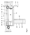
- the train anchor acts as a joint in an impact, so that the cross member is pivoted in the region of its front end together with the guard rail up and thereby increases the effective height of the guardrail. In this way, the risk is reduced that the guardrail in an impact, especially by higher vehicles, is run over.
- a traffic guidance device 1 is mounted on the edge of roadways for motor vehicles, to prevent vehicles coming off the road from passing over the edge of the roadway. This is especially important on bridges, especially on motorway bridges. Furthermore, the traffic guidance facility 1 also be arranged between roads with oncoming traffic.
- the traffic guidance device 1 extends along a roadway direction 2 and, except for connecting points not shown substantially along the direction 2, has the same cross section.
- the device 1 may be appropriate as mentioned at the edge of roadways or between lanes for the separation of opposing traffic. In this case, the traffic guidance device is designed so that guardrails are arranged on both sides.
- the traffic guidance device 1 is, in particular, a guard rail used by default in German motorways, which is referred to as a simple distance protection barrier, abbreviated EDSP.
- EDSP simple distance protection barrier
- the device 1 has arranged at regular intervals, connected to the bottom 3, vertically extending supports 4.
- the supports 4 may have any profile, in particular a T-profile, U-profile, W-profile or E-profile. In the present case, an E-profile (Sigma profile) is shown.
- the supports 4 each have at their lower end a firmly connected to them base plate 5, which is connected via anchors or screws 6 to the bottom 3.
- the floor 3 may be concrete or asphalt. Accordingly, the screws 6 are concrete screws or asphalt screws.
- the supports 4 can also be formed without the bottom plates 5 and then rammed directly into the ground.
- each a horizontally extending cross member 7 is fixed, which extends along a direction perpendicular to the direction 2, pointing to the roadway 2, horizontal transverse direction 8.
- the opposite end 8 of the cross member 7 is referred to as the rear end 9 and the end lying in the direction 8 as a front end 10.
- a standard guard rail 11 is fixed, which extends along the direction 2.
- the cross member 7 is made of bent sheet steel in one piece. He has at its upper edge a U-shaped cross-section, integrally formed with the cross member 7, upper support web 12. At the bottom there is a weak trained, lower support web 13, which is not quite applied to the lower part of the guard rail 11 and supports a pivoting up of the cross member 7 in an impact. Between the webs 12 and 13 is a substantially planar plate 14. Along the direction 8 are the upper support web 12 and the lower support web 13 with respect to the plate 14, wherein in this area the lower support web 13 weaker is formed as the upper support web 12. The free ends of the support webs 12 and 13 are located on the inside of the guardrail 11 at.
- the guardrail 11 is integrally formed and formed of sheet steel. It has in the mounted state from top to bottom described away from the roadway against the direction 8 facing web 15, a downwardly adjoining, substantially vertically extending upper band 16, one of the band 16 to the rear receding upper edge 17, a adjoining, substantially vertically extending groove bottom 18, an obliquely backward lower flank 19, an adjoining, vertically extending lower band 20 and an obliquely rearwardly projecting lower web 21.
- These different sections of guardrail 11 delimit several depressions.
- two recesses 41 are formed, on the one hand by the upper web 15, the upper band 16 and the upper flank 17 and on the other hand by the lower edge 19, the lower band 20 and the lower web 21.
- front end of the support bar 12 abuts against the rear side of the upper band 16.
- the front end of the lower support rib 13 abuts against the rear side of the lower band 20.
- front end of the plate 14 is a perpendicular to the direction 8 extending, integrally formed with the plate 14 tab 23 is provided, through which the guard rail 11 is screwed in the region of the groove bottom 8 with a screw 24.
- the supports 4 have, as mentioned, an E-shaped profile with substantially parallel to each other, outer legs 25, which are connected to each other via two inner legs 26.
- the supports 4 are integrally formed from sheet steel.
- the cross member 7 is connected in the region of its rear end via a bracket 27 with the support 4.
- the bracket 27 has a base plate 28 with two perpendicularly projecting jaws 29.
- the base plate 28 is screwed to the plate 14 via three screws 30, which are preferably arranged on the corners of an equilateral triangle.
- the jaws 29 of the bracket 27 engage around the outer legs 25.
- the jaws 29 are further screwed by screws 31 to the outer legs 25. From the rear end of the plate 14 is perpendicular to this a tab 32 protrudes.
- the train anchor 37 also referred to as a threaded rod, is a standard train anchor, as marketed, inter alia, under the brand "Dywidag".
- the tension anchor 37 has a substantially circular cross-section.
- the train anchor 37 is solid made of solid material, especially steel.
- the pull anchor 37 is not just a sheet steel or steel pipe.
- the tension anchor 37 has a diameter of 10 to 60 mm, in particular 20 to 40 mm, in particular 25 to 32 mm.
- On the outside, a coarse external thread 38 is provided on the outside.
- flats 39 are provided so that the train anchor 37 can be grasped and rotated with tools.
- the train anchor has a great inherent rigidity, so that shear forces and not only tensile forces along the longitudinal direction of the train-armature 37 are transferable.
- the train anchor 37 differs significantly from a steel cable.
- the draw anchor 37 does not have the problem of sagging and the rope must be pretensioned.
- the tensile anchor has a typical tensile strength of about 500-600 N / mm 2 .
- such strength is selected for the pull anchor 37 to ensure the best combination of tensile and compressive strength and flexibility. Higher strengths of more than 900 N / mm 2 could be prone to crack under sudden impact load without plastic deformation by constriction.
- the breaking value of train anchor 37 on train is between 100 and 1200 kN, in particular 150 to 630 kN. Relative to the individual diameters, the breaking loads are as follows: at 50 mm diameter 1080 kN, at 40 mm diameter 631 kN, at 32 mm diameter 442 kN, at 28 mm diameter 336 kN and at 16 mm diameter 111 kN. These figures are all purely exemplary. It is in principle possible to use also Buch anchor with a different cross section, in particular a rectangular cross section. However, train anchors with a substantially round or oval cross section are particularly preferred.
- Adjacent train anchors 37 are connected by connecting nuts, not shown, with a matching to the external thread 38 internal thread to an endless composite. Regarding the connection of adjacent train anchors is on the DE 10 2006 001 980.6 dated 13.01.2006 , there in particular Figs. 2 and 3 with the associated description, referenced.
- an additional stabilizing tie-arm 40 which may be designed as well as the train anchor 37.
- the stabilization train anchor 40 the stability of the guardrail 11 in the front area can be greatly increased.
- the addition of one or more stabilizing tension armatures 40 is not required.
- the train anchor 37 is first connected to the each adjacent in the direction of 2 train anchors, as described above, via connecting nuts. It thus forms an endless train anchor.
- each support 4 of the train anchor is guided by a sleeve 34 and thus secured via the cross member 7 to the corresponding support 4. If it now comes to the impact of a motor vehicle on the guardrail 11, the guard rail 11 there and the adjacent supports 4 are pressed against the direction 8 to the rear. Frequently, this leads to a tearing of the connection between the cross member 7 and the associated support 4 at the point, which without the present invention would lead to a considerable destabilization of the traffic guidance device 1 in this area.
- the guardrail Upon impact, the guardrail is pivoted substantially about the axis of rotation of the train-armature 37 upwards.
- the angle b occurring in this case at the end of the deformation can be, for example, between 95 ° to 180 °, in particular 110 ° to 150 °, whereby this is only rough Estimates are.
- the cross member 7 behaves during the impact thus approximately as if it were pivotally hinged to the train anchor 37, wherein a completely free pivoting of the cross member after the breaking of the screws 30 is prevented by the fact that the guardrail 11 also a quasi-endless belt represents and is kept stable in the non-impact affected areas, which counteracts the folding.
- the screws 30 do not break, but buckle the supports 4.
- the angle b changes only slightly. The pivoting of the guardrail 11 takes place nevertheless.
- the pull anchor 37 is slightly deformed in the region of the rear impact, whereby a wedging of the tension anchor in the adjacent sleeves 34 occurs.
- the external thread 38 is formed after wedging in the sleeves 34 an automatic locking, so that the train anchor 37 in the sleeves 34 can not be moved freely.
- the tension anchor 37 may be advantageous to lower the tension anchor 37 lower than shown in FIG. 2, for example at the level of the lower support web 13 on the cross member 7.
- the tab 32 has a further lower bore.
- the axis of rotation can be laid down, which may be useful depending on the type of expected impact and the relative height of the vehicle and crash barrier.
- existing traffic control devices are upgraded by the present invention and much higher retention capabilities and smaller deflections can be achieved. Retrofitting is only associated with low costs.
- the tension anchor 37 only has to be screwed on the rear of the already existing cross member 7.
- the structure of the traffic-guiding device 1 a corresponds to that of the traffic-guiding device 1 according to the first embodiment.
- the rear pull anchor 37 and the front stabilization pull anchor 40 are interconnected by transverse anchors 42.
- the transverse anchors 42 have a central rod 43, which in principle is the same type of tensile anchor or threaded rod as described above. At the ends of the rod 43 has two tubular sleeves 44 which are welded to the ends of the rod 43.
- the ends of the rod 43 are formed according to the outer shape of the sleeve 44 in order to improve the stability of the connection between sleeve 44 and rod 43.
- the sleeves 44 are pushed onto the pull anchors 37 and 40, respectively, so that the respective transverse armature 42 connects the pull anchors 37 and 40 in the transverse direction 8.
- a transverse armature 42 are provided at regular intervals. These are fixed via grub screws 45 in the sleeves 44 on the train anchors 37 and 40 respectively.
- the transverse anchors 42 are arranged over the length of the traffic-guiding device 1 a at regular intervals, for example every two meters, three meters or four meters.
- the stability of the traffic-guiding device 1 a against a collision against the direction 8 is greatly increased.
- the train anchors 37 and 40 do not bend individually upon impact of a motor vehicle, but remain stiff. This is a similar phenomenon that accounts for the stiffness of a double-T carrier over two flat carriers arranged one behind the other.
- the stability of the traffic guidance device 1a is particularly increased when the train anchors 37 and 40 connected by the transverse anchor 42 in the transverse direction 8, d. H. perpendicular to the lane direction 2, are offset, d. H. from the perspective of an impacting vehicle are arranged one behind the other. In this case, it is not necessary for the pull anchors 37 and 40 to be arranged at the same height.
- the typical post distance of 1.33 m to 2.50 m can be increased to over 4 m in conventional systems, without reducing the stability of the traffic guidance device 1a against impact. This results in a weight and thus material savings of 30% to 40%.
Landscapes
- Engineering & Computer Science (AREA)
- Architecture (AREA)
- Civil Engineering (AREA)
- Structural Engineering (AREA)
- Refuge Islands, Traffic Blockers, Or Guard Fence (AREA)
- Traffic Control Systems (AREA)
Applications Claiming Priority (2)
| Application Number | Priority Date | Filing Date | Title |
|---|---|---|---|
| DE102006005583 | 2006-02-06 | ||
| DE102006052911A DE102006052911A1 (de) | 2006-02-06 | 2006-11-08 | Verkehrs-Leit-Einrichtung |
Publications (2)
| Publication Number | Publication Date |
|---|---|
| EP1816263A1 true EP1816263A1 (fr) | 2007-08-08 |
| EP1816263B1 EP1816263B1 (fr) | 2010-03-10 |
Family
ID=37946738
Family Applications (1)
| Application Number | Title | Priority Date | Filing Date |
|---|---|---|---|
| EP07001811A Not-in-force EP1816263B1 (fr) | 2006-02-06 | 2007-01-27 | Dispositif de guidage routier |
Country Status (3)
| Country | Link |
|---|---|
| EP (1) | EP1816263B1 (fr) |
| AT (1) | ATE460536T1 (fr) |
| DE (2) | DE102006052911A1 (fr) |
Cited By (4)
| Publication number | Priority date | Publication date | Assignee | Title |
|---|---|---|---|---|
| EP1921211A1 (fr) * | 2006-11-08 | 2008-05-14 | TOGE-Dübel A. Gerhard KG | Dispositif de commande du trafic |
| WO2011138291A1 (fr) * | 2010-05-04 | 2011-11-10 | Sah Verkehrstechnik Gmbh | Glissière de sécurité |
| WO2012139931A1 (fr) | 2011-04-15 | 2012-10-18 | Stahlwerk Annahütte Max Aicher GmbH & Co. KG | Système de guidage du trafic muni d'éléments raidisseurs |
| WO2022078201A1 (fr) * | 2020-10-15 | 2022-04-21 | 余永成 | Barre transversale et glissière de sécurité routière |
Families Citing this family (1)
| Publication number | Priority date | Publication date | Assignee | Title |
|---|---|---|---|---|
| DE102009034758A1 (de) * | 2009-07-25 | 2011-01-27 | Stahlwerk Annahütte Max Aicher GmbH & Co. KG | Schutzplanke |
Citations (6)
| Publication number | Priority date | Publication date | Assignee | Title |
|---|---|---|---|---|
| AT243845B (de) * | 1964-02-03 | 1965-12-10 | Oesterr Alpine Montan | Straßenbegrenzung |
| CH419214A (de) * | 1965-01-20 | 1966-08-31 | Gysi Ag Geb | Leitplankenanordnung mit profilierten Leitplanken |
| DE1534540B1 (de) * | 1966-05-28 | 1969-09-18 | Neher Maschinenfabrik Stahl U | Leitplanke fuer Strassen,insbesondere in Einfachausfuehrung |
| EP0356686A1 (fr) * | 1988-08-03 | 1990-03-07 | METALMECCANICA FRACASSO S.p.A. | Barrière de sécurité à glissière |
| WO1999036631A1 (fr) * | 1998-01-19 | 1999-07-22 | Ilva Pali Dalmine S.R.L. | Glissiere de securite amelioree semi-rigide presentant une caracteristique de correction de position et de dissipation d'energie |
| DE102005004918A1 (de) | 2005-02-02 | 2005-12-01 | Spig Schutzplanken-Produktions-Gesellschaft Mbh & Co Kg | Leitplankenanordnung |
-
2006
- 2006-11-08 DE DE102006052911A patent/DE102006052911A1/de not_active Withdrawn
-
2007
- 2007-01-27 EP EP07001811A patent/EP1816263B1/fr not_active Not-in-force
- 2007-01-27 AT AT07001811T patent/ATE460536T1/de active
- 2007-01-27 DE DE502007003048T patent/DE502007003048D1/de active Active
Patent Citations (6)
| Publication number | Priority date | Publication date | Assignee | Title |
|---|---|---|---|---|
| AT243845B (de) * | 1964-02-03 | 1965-12-10 | Oesterr Alpine Montan | Straßenbegrenzung |
| CH419214A (de) * | 1965-01-20 | 1966-08-31 | Gysi Ag Geb | Leitplankenanordnung mit profilierten Leitplanken |
| DE1534540B1 (de) * | 1966-05-28 | 1969-09-18 | Neher Maschinenfabrik Stahl U | Leitplanke fuer Strassen,insbesondere in Einfachausfuehrung |
| EP0356686A1 (fr) * | 1988-08-03 | 1990-03-07 | METALMECCANICA FRACASSO S.p.A. | Barrière de sécurité à glissière |
| WO1999036631A1 (fr) * | 1998-01-19 | 1999-07-22 | Ilva Pali Dalmine S.R.L. | Glissiere de securite amelioree semi-rigide presentant une caracteristique de correction de position et de dissipation d'energie |
| DE102005004918A1 (de) | 2005-02-02 | 2005-12-01 | Spig Schutzplanken-Produktions-Gesellschaft Mbh & Co Kg | Leitplankenanordnung |
Cited By (4)
| Publication number | Priority date | Publication date | Assignee | Title |
|---|---|---|---|---|
| EP1921211A1 (fr) * | 2006-11-08 | 2008-05-14 | TOGE-Dübel A. Gerhard KG | Dispositif de commande du trafic |
| WO2011138291A1 (fr) * | 2010-05-04 | 2011-11-10 | Sah Verkehrstechnik Gmbh | Glissière de sécurité |
| WO2012139931A1 (fr) | 2011-04-15 | 2012-10-18 | Stahlwerk Annahütte Max Aicher GmbH & Co. KG | Système de guidage du trafic muni d'éléments raidisseurs |
| WO2022078201A1 (fr) * | 2020-10-15 | 2022-04-21 | 余永成 | Barre transversale et glissière de sécurité routière |
Also Published As
| Publication number | Publication date |
|---|---|
| DE502007003048D1 (de) | 2010-04-22 |
| EP1816263B1 (fr) | 2010-03-10 |
| DE102006052911A1 (de) | 2007-09-20 |
| ATE460536T1 (de) | 2010-03-15 |
Similar Documents
| Publication | Publication Date | Title |
|---|---|---|
| DE69832599T2 (de) | Leitplankenpfosten mit sollbruchstelle für schienenende | |
| DE69816898T2 (de) | Bodenverankerung für ein Schutzplanken-Ende | |
| EP1762660B1 (fr) | Dispositif de guidage routier | |
| EP1816263B1 (fr) | Dispositif de guidage routier | |
| EP2900873B1 (fr) | Élément de délimitation de surfaces de circulation | |
| EP3827128B1 (fr) | Système de retenue de véhicule avec montant | |
| EP1926859B1 (fr) | Barriere de protection en madriers | |
| EP1722037B1 (fr) | Dispositif de guidage de la circulation | |
| DE102007063511B4 (de) | Schutzeinrichtung an Verkehrswegen | |
| WO2011066973A1 (fr) | Construction de barrière de sécurité | |
| DE202009000423U1 (de) | Fahrzeugrückhaltesystem | |
| EP0761889B1 (fr) | Disposition de barrière routière | |
| EP2567030B1 (fr) | Glissière de sécurité | |
| EP2034094B1 (fr) | Dispositif conducteur sur des trajectoires de trafic doté de deux systèmes de retenue à raideur différente et d'une construction de passage entre ceux-ci | |
| WO2012139931A1 (fr) | Système de guidage du trafic muni d'éléments raidisseurs | |
| DE102008048810A1 (de) | Verkehrs-Leit-Einrichtung | |
| EP1921211B1 (fr) | Dispositif de guidage du trafic | |
| DE102016118398B4 (de) | Fahrzeugrückhaltesystem | |
| DE102008039851B4 (de) | Fahrzeugrückhaltesystem | |
| EP1876300B1 (fr) | Barrière de sécurité d'acier | |
| EP1784541B1 (fr) | Systeme de retenue pour voies de circulation | |
| DE202006013759U1 (de) | Schutzeinrichtung an Verkehrswegen | |
| DE20016163U1 (de) | Halteelement für Schutzplanken | |
| DE102005021425A1 (de) | Verkehrs-Leit-Einrichtung |
Legal Events
| Date | Code | Title | Description |
|---|---|---|---|
| PUAI | Public reference made under article 153(3) epc to a published international application that has entered the european phase |
Free format text: ORIGINAL CODE: 0009012 |
|
| AK | Designated contracting states |
Kind code of ref document: A1 Designated state(s): AT BE BG CH CY CZ DE DK EE ES FI FR GB GR HU IE IS IT LI LT LU LV MC NL PL PT RO SE SI SK TR |
|
| AX | Request for extension of the european patent |
Extension state: AL BA HR MK YU |
|
| 17P | Request for examination filed |
Effective date: 20080111 |
|
| 17Q | First examination report despatched |
Effective date: 20080227 |
|
| AKX | Designation fees paid |
Designated state(s): AT BE BG CH CY CZ DE DK EE ES FI FR GB GR HU IE IS IT LI LT LU LV MC NL PL PT RO SE SI SK TR |
|
| GRAP | Despatch of communication of intention to grant a patent |
Free format text: ORIGINAL CODE: EPIDOSNIGR1 |
|
| GRAS | Grant fee paid |
Free format text: ORIGINAL CODE: EPIDOSNIGR3 |
|
| GRAA | (expected) grant |
Free format text: ORIGINAL CODE: 0009210 |
|
| AK | Designated contracting states |
Kind code of ref document: B1 Designated state(s): AT BE BG CH CY CZ DE DK EE ES FI FR GB GR HU IE IS IT LI LT LU LV MC NL PL PT RO SE SI SK TR |
|
| REG | Reference to a national code |
Ref country code: GB Ref legal event code: FG4D Free format text: NOT ENGLISH |
|
| REG | Reference to a national code |
Ref country code: CH Ref legal event code: EP |
|
| REG | Reference to a national code |
Ref country code: IE Ref legal event code: FG4D |
|
| REF | Corresponds to: |
Ref document number: 502007003048 Country of ref document: DE Date of ref document: 20100422 Kind code of ref document: P |
|
| REG | Reference to a national code |
Ref country code: NL Ref legal event code: T3 |
|
| PG25 | Lapsed in a contracting state [announced via postgrant information from national office to epo] |
Ref country code: LT Free format text: LAPSE BECAUSE OF FAILURE TO SUBMIT A TRANSLATION OF THE DESCRIPTION OR TO PAY THE FEE WITHIN THE PRESCRIBED TIME-LIMIT Effective date: 20100310 |
|
| LTIE | Lt: invalidation of european patent or patent extension |
Effective date: 20100310 |
|
| PG25 | Lapsed in a contracting state [announced via postgrant information from national office to epo] |
Ref country code: FI Free format text: LAPSE BECAUSE OF FAILURE TO SUBMIT A TRANSLATION OF THE DESCRIPTION OR TO PAY THE FEE WITHIN THE PRESCRIBED TIME-LIMIT Effective date: 20100310 Ref country code: LV Free format text: LAPSE BECAUSE OF FAILURE TO SUBMIT A TRANSLATION OF THE DESCRIPTION OR TO PAY THE FEE WITHIN THE PRESCRIBED TIME-LIMIT Effective date: 20100310 Ref country code: PL Free format text: LAPSE BECAUSE OF FAILURE TO SUBMIT A TRANSLATION OF THE DESCRIPTION OR TO PAY THE FEE WITHIN THE PRESCRIBED TIME-LIMIT Effective date: 20100310 Ref country code: SI Free format text: LAPSE BECAUSE OF FAILURE TO SUBMIT A TRANSLATION OF THE DESCRIPTION OR TO PAY THE FEE WITHIN THE PRESCRIBED TIME-LIMIT Effective date: 20100310 |
|
| REG | Reference to a national code |
Ref country code: IE Ref legal event code: FD4D |
|
| PG25 | Lapsed in a contracting state [announced via postgrant information from national office to epo] |
Ref country code: EE Free format text: LAPSE BECAUSE OF FAILURE TO SUBMIT A TRANSLATION OF THE DESCRIPTION OR TO PAY THE FEE WITHIN THE PRESCRIBED TIME-LIMIT Effective date: 20100310 Ref country code: CY Free format text: LAPSE BECAUSE OF FAILURE TO SUBMIT A TRANSLATION OF THE DESCRIPTION OR TO PAY THE FEE WITHIN THE PRESCRIBED TIME-LIMIT Effective date: 20100310 Ref country code: ES Free format text: LAPSE BECAUSE OF FAILURE TO SUBMIT A TRANSLATION OF THE DESCRIPTION OR TO PAY THE FEE WITHIN THE PRESCRIBED TIME-LIMIT Effective date: 20100621 Ref country code: GR Free format text: LAPSE BECAUSE OF FAILURE TO SUBMIT A TRANSLATION OF THE DESCRIPTION OR TO PAY THE FEE WITHIN THE PRESCRIBED TIME-LIMIT Effective date: 20100611 Ref country code: RO Free format text: LAPSE BECAUSE OF FAILURE TO SUBMIT A TRANSLATION OF THE DESCRIPTION OR TO PAY THE FEE WITHIN THE PRESCRIBED TIME-LIMIT Effective date: 20100310 Ref country code: SE Free format text: LAPSE BECAUSE OF FAILURE TO SUBMIT A TRANSLATION OF THE DESCRIPTION OR TO PAY THE FEE WITHIN THE PRESCRIBED TIME-LIMIT Effective date: 20100310 |
|
| PG25 | Lapsed in a contracting state [announced via postgrant information from national office to epo] |
Ref country code: IS Free format text: LAPSE BECAUSE OF FAILURE TO SUBMIT A TRANSLATION OF THE DESCRIPTION OR TO PAY THE FEE WITHIN THE PRESCRIBED TIME-LIMIT Effective date: 20100710 Ref country code: SK Free format text: LAPSE BECAUSE OF FAILURE TO SUBMIT A TRANSLATION OF THE DESCRIPTION OR TO PAY THE FEE WITHIN THE PRESCRIBED TIME-LIMIT Effective date: 20100310 Ref country code: CZ Free format text: LAPSE BECAUSE OF FAILURE TO SUBMIT A TRANSLATION OF THE DESCRIPTION OR TO PAY THE FEE WITHIN THE PRESCRIBED TIME-LIMIT Effective date: 20100310 Ref country code: BG Free format text: LAPSE BECAUSE OF FAILURE TO SUBMIT A TRANSLATION OF THE DESCRIPTION OR TO PAY THE FEE WITHIN THE PRESCRIBED TIME-LIMIT Effective date: 20100610 |
|
| PLBE | No opposition filed within time limit |
Free format text: ORIGINAL CODE: 0009261 |
|
| STAA | Information on the status of an ep patent application or granted ep patent |
Free format text: STATUS: NO OPPOSITION FILED WITHIN TIME LIMIT |
|
| PG25 | Lapsed in a contracting state [announced via postgrant information from national office to epo] |
Ref country code: DK Free format text: LAPSE BECAUSE OF FAILURE TO SUBMIT A TRANSLATION OF THE DESCRIPTION OR TO PAY THE FEE WITHIN THE PRESCRIBED TIME-LIMIT Effective date: 20100310 Ref country code: IE Free format text: LAPSE BECAUSE OF FAILURE TO SUBMIT A TRANSLATION OF THE DESCRIPTION OR TO PAY THE FEE WITHIN THE PRESCRIBED TIME-LIMIT Effective date: 20100310 Ref country code: PT Free format text: LAPSE BECAUSE OF FAILURE TO SUBMIT A TRANSLATION OF THE DESCRIPTION OR TO PAY THE FEE WITHIN THE PRESCRIBED TIME-LIMIT Effective date: 20100712 |
|
| 26N | No opposition filed |
Effective date: 20101213 |
|
| REG | Reference to a national code |
Ref country code: NL Ref legal event code: SD Effective date: 20110408 |
|
| REG | Reference to a national code |
Ref country code: GB Ref legal event code: 732E Free format text: REGISTERED BETWEEN 20110505 AND 20110511 |
|
| REG | Reference to a national code |
Ref country code: DE Ref legal event code: R081 Ref document number: 502007003048 Country of ref document: DE Owner name: SAH VERKEHRSTECHNIK GMBH, DE Free format text: FORMER OWNER: TOGE-DUEBEL A. GERHARD KG, 90431 NUERNBERG, DE Effective date: 20110415 |
|
| REG | Reference to a national code |
Ref country code: FR Ref legal event code: TP |
|
| BERE | Be: lapsed |
Owner name: TOGE-DUBEL A. GERHARD K.G. Effective date: 20110131 |
|
| PG25 | Lapsed in a contracting state [announced via postgrant information from national office to epo] |
Ref country code: MC Free format text: LAPSE BECAUSE OF NON-PAYMENT OF DUE FEES Effective date: 20110131 |
|
| REG | Reference to a national code |
Ref country code: CH Ref legal event code: PL |
|
| PG25 | Lapsed in a contracting state [announced via postgrant information from national office to epo] |
Ref country code: LI Free format text: LAPSE BECAUSE OF NON-PAYMENT OF DUE FEES Effective date: 20110131 Ref country code: CH Free format text: LAPSE BECAUSE OF NON-PAYMENT OF DUE FEES Effective date: 20110131 |
|
| PG25 | Lapsed in a contracting state [announced via postgrant information from national office to epo] |
Ref country code: BE Free format text: LAPSE BECAUSE OF NON-PAYMENT OF DUE FEES Effective date: 20110131 |
|
| PG25 | Lapsed in a contracting state [announced via postgrant information from national office to epo] |
Ref country code: LU Free format text: LAPSE BECAUSE OF NON-PAYMENT OF DUE FEES Effective date: 20110127 |
|
| PG25 | Lapsed in a contracting state [announced via postgrant information from national office to epo] |
Ref country code: TR Free format text: LAPSE BECAUSE OF FAILURE TO SUBMIT A TRANSLATION OF THE DESCRIPTION OR TO PAY THE FEE WITHIN THE PRESCRIBED TIME-LIMIT Effective date: 20100310 |
|
| PG25 | Lapsed in a contracting state [announced via postgrant information from national office to epo] |
Ref country code: HU Free format text: LAPSE BECAUSE OF FAILURE TO SUBMIT A TRANSLATION OF THE DESCRIPTION OR TO PAY THE FEE WITHIN THE PRESCRIBED TIME-LIMIT Effective date: 20100310 |
|
| REG | Reference to a national code |
Ref country code: FR Ref legal event code: PLFP Year of fee payment: 10 |
|
| PGFP | Annual fee paid to national office [announced via postgrant information from national office to epo] |
Ref country code: NL Payment date: 20160121 Year of fee payment: 10 |
|
| PGFP | Annual fee paid to national office [announced via postgrant information from national office to epo] |
Ref country code: DE Payment date: 20160321 Year of fee payment: 10 Ref country code: IT Payment date: 20160122 Year of fee payment: 10 |
|
| PGFP | Annual fee paid to national office [announced via postgrant information from national office to epo] |
Ref country code: FR Payment date: 20160121 Year of fee payment: 10 Ref country code: GB Payment date: 20160122 Year of fee payment: 10 Ref country code: AT Payment date: 20151222 Year of fee payment: 10 |
|
| REG | Reference to a national code |
Ref country code: DE Ref legal event code: R119 Ref document number: 502007003048 Country of ref document: DE |
|
| REG | Reference to a national code |
Ref country code: NL Ref legal event code: MM Effective date: 20170201 |
|
| REG | Reference to a national code |
Ref country code: AT Ref legal event code: MM01 Ref document number: 460536 Country of ref document: AT Kind code of ref document: T Effective date: 20170127 |
|
| GBPC | Gb: european patent ceased through non-payment of renewal fee |
Effective date: 20170127 |
|
| REG | Reference to a national code |
Ref country code: FR Ref legal event code: ST Effective date: 20170929 |
|
| PG25 | Lapsed in a contracting state [announced via postgrant information from national office to epo] |
Ref country code: FR Free format text: LAPSE BECAUSE OF NON-PAYMENT OF DUE FEES Effective date: 20170131 Ref country code: AT Free format text: LAPSE BECAUSE OF NON-PAYMENT OF DUE FEES Effective date: 20170127 |
|
| PG25 | Lapsed in a contracting state [announced via postgrant information from national office to epo] |
Ref country code: NL Free format text: LAPSE BECAUSE OF NON-PAYMENT OF DUE FEES Effective date: 20170201 Ref country code: DE Free format text: LAPSE BECAUSE OF NON-PAYMENT OF DUE FEES Effective date: 20170801 Ref country code: GB Free format text: LAPSE BECAUSE OF NON-PAYMENT OF DUE FEES Effective date: 20170127 |
|
| PG25 | Lapsed in a contracting state [announced via postgrant information from national office to epo] |
Ref country code: IT Free format text: LAPSE BECAUSE OF NON-PAYMENT OF DUE FEES Effective date: 20170127 |