EP1816280A2 - Ensemble de lamelles pour façades - Google Patents
Ensemble de lamelles pour façades Download PDFInfo
- Publication number
- EP1816280A2 EP1816280A2 EP07001802A EP07001802A EP1816280A2 EP 1816280 A2 EP1816280 A2 EP 1816280A2 EP 07001802 A EP07001802 A EP 07001802A EP 07001802 A EP07001802 A EP 07001802A EP 1816280 A2 EP1816280 A2 EP 1816280A2
- Authority
- EP
- European Patent Office
- Prior art keywords
- foot part
- receiving
- arrangement according
- slat
- receiving grooves
- Prior art date
- Legal status (The legal status is an assumption and is not a legal conclusion. Google has not performed a legal analysis and makes no representation as to the accuracy of the status listed.)
- Withdrawn
Links
- 241000446313 Lamella Species 0.000 claims abstract description 8
- 125000006850 spacer group Chemical group 0.000 claims description 10
- 230000037431 insertion Effects 0.000 claims description 4
- 238000003780 insertion Methods 0.000 claims description 4
- 239000011521 glass Substances 0.000 description 1
- 238000004519 manufacturing process Methods 0.000 description 1
Images


Classifications
-
- E—FIXED CONSTRUCTIONS
- E04—BUILDING
- E04F—FINISHING WORK ON BUILDINGS, e.g. STAIRS, FLOORS
- E04F10/00—Sunshades, e.g. Florentine blinds or jalousies; Outside screens; Awnings or baldachins
- E04F10/08—Sunshades, e.g. Florentine blinds or jalousies; Outside screens; Awnings or baldachins of a plurality of similar rigid parts, e.g. slabs, lamellae
-
- E—FIXED CONSTRUCTIONS
- E06—DOORS, WINDOWS, SHUTTERS, OR ROLLER BLINDS IN GENERAL; LADDERS
- E06B—FIXED OR MOVABLE CLOSURES FOR OPENINGS IN BUILDINGS, VEHICLES, FENCES OR LIKE ENCLOSURES IN GENERAL, e.g. DOORS, WINDOWS, BLINDS, GATES
- E06B7/00—Special arrangements or measures in connection with doors or windows
- E06B7/02—Special arrangements or measures in connection with doors or windows for providing ventilation, e.g. through double windows; Arrangement of ventilation roses
- E06B7/08—Louvre doors, windows or grilles
- E06B7/084—Louvre doors, windows or grilles with rotatable lamellae
-
- E—FIXED CONSTRUCTIONS
- E04—BUILDING
- E04F—FINISHING WORK ON BUILDINGS, e.g. STAIRS, FLOORS
- E04F10/00—Sunshades, e.g. Florentine blinds or jalousies; Outside screens; Awnings or baldachins
- E04F10/08—Sunshades, e.g. Florentine blinds or jalousies; Outside screens; Awnings or baldachins of a plurality of similar rigid parts, e.g. slabs, lamellae
- E04F10/10—Sunshades, e.g. Florentine blinds or jalousies; Outside screens; Awnings or baldachins of a plurality of similar rigid parts, e.g. slabs, lamellae collapsible or extensible; metallic Florentine blinds; awnings with movable parts such as louvres
Definitions
- the invention relates to a plurality of preferably mutually parallel slats existing lamellar arrangement for facades, cantilevered projections, glazed roofs and the like., With the slats supporting holding elements, which are fixed to rails.
- the invention has the object of providing a lamellar arrangement of the type mentioned in such a way that the alignment of the slats is achieved with only one easy to manufacture and easy to mount retaining element.
- the holding element is formed of a lamella carrying boom part and a cross in the rail foot part, wherein the foot on at least one of its two cross-leg between the legs of the rail with at least two over the entire End face extending, mutually angled extending receiving grooves is provided which receives the end face of the foot towards projecting web of the profile designed as a C-profile rail.
- the advantage achieved by the invention consists essentially in that the boom part can be aligned in different angular position to the rail by the foot of the support member is inserted with the appropriate receiving groove in the rail. It is thus possible to adjust with a single holding element different angular positions for the slats already during assembly.
- the respective angular position to be selected in particular is also determined by whether the rails vertically, horizontally or - are mounted in an oblique orientation - for example, in sloping glass roofs.
- the end faces of the foot part are provided with three receiving grooves. In principle, however, it is also possible instead to provide only two or even more than three receiving grooves.
- the mounting of the holding elements can be particularly simplified in that the foot part has a cylindrical shape, wherein the receiving grooves intersect centrally in the circular end faces.
- the grooves include an angle of 20 ° with each other. In principle, however, it is also possible to choose a smaller or larger angle here.
- a spacer is arranged in each case between two holding elements.
- the receiving grooves of both end faces are each connected to one another via a receiving gap arranged in the lateral surface of the foot part.
- the spacer is provided at the end with Einsteckleisten, each engage in those receiving gap, the profile rails receiving groove is assigned.
- a complete coverage of the open towards the slats profile rail is achieved at the same time.
- the male strip has a locking projection arranged at a distance from its free end for provided in each of the receiving slots locking grooves.
- the boom part at its end remote from the foot part has a receiving holder for one edge of the blade, and that in each case a Einrasthinterschneidung is arranged for the other edge of the blade in the region of the foot part on both sides of the jib part.
- the receptacle holder provided at the free end of the cantilever part is designed to be round, so that the lamella can easily be fastened by one or the other side.
- the lamellar arrangement has profiled rails 2 on which holding elements 3 are fixed, which support the lamellae 1.
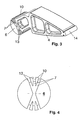
- the retaining element 3 consists of a boom part 4 supporting the lamella 1 and of a foot part 5 engaging in the profile rail 2.
- the foot part 5 is provided on both of its two end faces 6 which reach between the limbs of the profile rail 2 provided with three over the entire end face 6 extending grooves 7 which extend at an angle to each other.
- These receiving grooves 7 engage in the assembled state in the two projecting webs 8 of the profile rail 2 becamebileten as C-profile, as can be seen from Figure 1.
- the receiving grooves 7 are expediently arranged at the same angle to each other, as can be seen in particular from Figure 4.
- the foot part 5 has a cylindrical shape, wherein the receiving grooves intersect centrally in the circular end faces 6. As a result, the foot part 5 can be easily arranged in any desired angular position in the rail 2.
- the receiving grooves 7 form an angle of 20 ° with each other; In principle, however, there is also the possibility of providing deviating angular dimensions here.
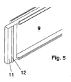
- a spacer 9 is provided in each case, which ensures that the holding elements 3 comply with each other evenly spaced.
- the receiving grooves 7 of both end faces 6 are connected to each other via a receiving gap 10 arranged in the lateral surface of the foot part 5.
- the spacer 9 thus extends almost flush with the projecting webs 8 of the rail 2, so that the interior is closed by the spacers 9.
- the insertion strip 11 has, as is apparent from the figure 5, at least one arranged at a distance from its free end latching projection 12 provided in each of the receiving slots 10 locking grooves 13. In this way, a secure connection between the spacers 9 and the holding elements 3 is ensured. This results in a noticeable end position during assembly, also results in the snapping that tolerances are ineffective, so a wobble of the holder is avoided.
- the boom part 4 of the support member 3 has at its end facing away from the foot part 5 a receiving holder 14 for the one edge of the blade 1, while in the region of the foot part 5 on both sides of the boom part 4 each Einrasthinterschneidung 15 is arranged for the other edge of the blade 1 , As a result, it is possible to arrange the lamella 1 selectively on one or the other side of the holding element 3, as can be seen by way of example from FIGS. 7 and 8.
- the at the free end of the Boom part 4 arranged receiving holder 14 is advantageously formed circular, which facilitates the optional assembly of the blade 1 from one side or the other.
Landscapes
- Engineering & Computer Science (AREA)
- Civil Engineering (AREA)
- Structural Engineering (AREA)
- Architecture (AREA)
- Specific Sealing Or Ventilating Devices For Doors And Windows (AREA)
- Grates (AREA)
- Mutual Connection Of Rods And Tubes (AREA)
- Chain Conveyers (AREA)
- Door And Window Frames Mounted To Openings (AREA)
Applications Claiming Priority (1)
| Application Number | Priority Date | Filing Date | Title |
|---|---|---|---|
| DE102006005235A DE102006005235B4 (de) | 2006-02-06 | 2006-02-06 | Lamellenanordnung für Fassaden |
Publications (2)
| Publication Number | Publication Date |
|---|---|
| EP1816280A2 true EP1816280A2 (fr) | 2007-08-08 |
| EP1816280A3 EP1816280A3 (fr) | 2011-11-16 |
Family
ID=38015568
Family Applications (1)
| Application Number | Title | Priority Date | Filing Date |
|---|---|---|---|
| EP07001802A Withdrawn EP1816280A3 (fr) | 2006-02-06 | 2007-01-27 | Ensemble de lamelles pour façades |
Country Status (2)
| Country | Link |
|---|---|
| EP (1) | EP1816280A3 (fr) |
| DE (1) | DE102006005235B4 (fr) |
Families Citing this family (2)
| Publication number | Priority date | Publication date | Assignee | Title |
|---|---|---|---|---|
| DE102018106519B4 (de) * | 2018-03-20 | 2023-06-29 | Technische Hochschule Nürnberg Georg Simon Ohm | Profilelement zur Abdeckung einer Gebäudehülle |
| GB2629605A (en) * | 2023-05-03 | 2024-11-06 | Trevor Mcgrath | Building louvre assembly |
Family Cites Families (4)
| Publication number | Priority date | Publication date | Assignee | Title |
|---|---|---|---|---|
| DE7522884U (de) * | 1974-07-22 | 1979-10-04 | Ingenioerfirma Lund-Hansen A/S, Skoedstrup (Daenemark) | Sonnenjalousie o.dgl. |
| DE9401939U1 (de) * | 1994-02-05 | 1994-03-31 | E.M.B. Metallbau und Brandschutztechnik GmbH, 46446 Emmerich | Sonnenschutzeinrichtung |
| DE10009565A1 (de) * | 2000-02-29 | 2001-08-30 | Colt Internat Holdings Ag Baar | Sonnenschutzeinrichtung |
| DE20311814U1 (de) * | 2003-07-31 | 2004-12-02 | SCHÜCO International KG | Lamellenelement |
-
2006
- 2006-02-06 DE DE102006005235A patent/DE102006005235B4/de not_active Expired - Fee Related
-
2007
- 2007-01-27 EP EP07001802A patent/EP1816280A3/fr not_active Withdrawn
Also Published As
| Publication number | Publication date |
|---|---|
| DE102006005235B4 (de) | 2009-05-07 |
| EP1816280A3 (fr) | 2011-11-16 |
| DE102006005235A1 (de) | 2007-08-16 |
Similar Documents
| Publication | Publication Date | Title |
|---|---|---|
| EP1878847B1 (fr) | Structure de mur rideau | |
| EP2063047B1 (fr) | Système de rails profilés | |
| DE102006057491A1 (de) | Paneel sowie Bodenbelag | |
| DE3200310A1 (de) | Gestell aus mehreren profilstaeben | |
| EP0180837A2 (fr) | Jeu de pièces séparées pour un dispositif de fixation de murs rideaux | |
| EP0199025B1 (fr) | Agencement de fixation pour les lamelles d'un store vénitien | |
| CH707332B1 (de) | Rahmensystem für ein Insekten- und/oder Pollenschutzgitter. | |
| AT511046B1 (de) | Rahmensystem eines partikelschutzgitters | |
| EP2816172A2 (fr) | Système de montage pour un revêtement de sol | |
| DE202012104033U1 (de) | Haltevorrichtung für eine Brüstungs- oder Geländerplatte sowie Geländer oder Brüstung mit Scheibe | |
| EP0104428A2 (fr) | Latte ou plaque de support d'un revêtement de rideau pour un mur ou plafond | |
| DE9207859U1 (de) | Glasscheibenhalter | |
| EP1816280A2 (fr) | Ensemble de lamelles pour façades | |
| WO2009006926A1 (fr) | CONCEPT DE PANNEAU DE PAROI À 45º | |
| DE102010060672B4 (de) | Fenster- oder Türrahmen | |
| EP1830029A2 (fr) | Ensemble de lamelles pour façades | |
| EP2754810B1 (fr) | Paroi de séparation | |
| DE3733359C2 (fr) | ||
| EP1503029B1 (fr) | Système de jalousies | |
| DE69002041T2 (de) | Montagesystem und montageelemente für trennwände in bürogebäuden und dergleichen. | |
| DE102017000924A1 (de) | Plattenhalter | |
| EP0152813A2 (fr) | Système modulaire pour une bande de fixation pour petits bois | |
| DE102012104000B4 (de) | Halter zur Fixierung eines Isolationskörpers an einer Pfosten- und Riegelanordnung und eine solche Pfosten- und Riegelanordnung | |
| DE20203512U1 (de) | Rahmensystemanordnung | |
| EP3243413B1 (fr) | Dispositif de support de pièces décoratives pour des rebords de fenêtres |
Legal Events
| Date | Code | Title | Description |
|---|---|---|---|
| PUAI | Public reference made under article 153(3) epc to a published international application that has entered the european phase |
Free format text: ORIGINAL CODE: 0009012 |
|
| AK | Designated contracting states |
Kind code of ref document: A2 Designated state(s): AT BE BG CH CY CZ DE DK EE ES FI FR GB GR HU IE IS IT LI LT LU LV MC NL PL PT RO SE SI SK TR |
|
| AX | Request for extension of the european patent |
Extension state: AL BA HR MK YU |
|
| PUAL | Search report despatched |
Free format text: ORIGINAL CODE: 0009013 |
|
| AK | Designated contracting states |
Kind code of ref document: A3 Designated state(s): AT BE BG CH CY CZ DE DK EE ES FI FR GB GR HU IE IS IT LI LT LU LV MC NL PL PT RO SE SI SK TR |
|
| AX | Request for extension of the european patent |
Extension state: AL BA HR MK RS |
|
| RIC1 | Information provided on ipc code assigned before grant |
Ipc: E06B 7/084 20060101ALN20111013BHEP Ipc: E04F 10/08 20060101AFI20111013BHEP |
|
| AKX | Designation fees paid |
Designated state(s): AT BE BG CH CY CZ DE DK EE ES FI FR GB GR HU IE IS IT LI LT LU LV MC NL PL PT RO SE SI SK TR |
|
| STAA | Information on the status of an ep patent application or granted ep patent |
Free format text: STATUS: THE APPLICATION IS DEEMED TO BE WITHDRAWN |
|
| 18D | Application deemed to be withdrawn |
Effective date: 20120517 |