EP1816283A2 - Vorrichtung zum Verbinden von Parkettartige Platten oder -Stücke - Google Patents
Vorrichtung zum Verbinden von Parkettartige Platten oder -Stücke Download PDFInfo
- Publication number
- EP1816283A2 EP1816283A2 EP07380022A EP07380022A EP1816283A2 EP 1816283 A2 EP1816283 A2 EP 1816283A2 EP 07380022 A EP07380022 A EP 07380022A EP 07380022 A EP07380022 A EP 07380022A EP 1816283 A2 EP1816283 A2 EP 1816283A2
- Authority
- EP
- European Patent Office
- Prior art keywords
- pieces
- piece
- plaques
- parquet
- type
- Prior art date
- Legal status (The legal status is an assumption and is not a legal conclusion. Google has not performed a legal analysis and makes no representation as to the accuracy of the status listed.)
- Withdrawn
Links
Images




Classifications
-
- E—FIXED CONSTRUCTIONS
- E04—BUILDING
- E04F—FINISHING WORK ON BUILDINGS, e.g. STAIRS, FLOORS
- E04F15/00—Flooring
- E04F15/02—Flooring or floor layers composed of a number of similar elements
-
- E—FIXED CONSTRUCTIONS
- E04—BUILDING
- E04F—FINISHING WORK ON BUILDINGS, e.g. STAIRS, FLOORS
- E04F15/00—Flooring
- E04F15/02—Flooring or floor layers composed of a number of similar elements
- E04F15/06—Flooring or floor layers composed of a number of similar elements of metal, whether or not in combination with other material
-
- E—FIXED CONSTRUCTIONS
- E04—BUILDING
- E04F—FINISHING WORK ON BUILDINGS, e.g. STAIRS, FLOORS
- E04F2201/00—Joining sheets or plates or panels
- E04F2201/01—Joining sheets, plates or panels with edges in abutting relationship
- E04F2201/0123—Joining sheets, plates or panels with edges in abutting relationship by moving the sheets, plates or panels parallel to the abutting edges
-
- E—FIXED CONSTRUCTIONS
- E04—BUILDING
- E04F—FINISHING WORK ON BUILDINGS, e.g. STAIRS, FLOORS
- E04F2201/00—Joining sheets or plates or panels
- E04F2201/05—Separate connectors or inserts, e.g. pegs, pins, keys or strips
- E04F2201/0517—U- or C-shaped brackets and clamps
Definitions
- the present invention relates to a device for joining parquet-type plaques or pieces, with which notable advantages are contributed compared to previous floors of this type and which includes means of tongue-and-grooving between the different pieces.
- the device in question is based on the classical pieces or tiles constituting the floor or parquet, but endowed with certain characteristic means of securing which is explained below.
- the means of securing consist of certain angular projections located in at least one of the sides of the piece, and which collaborate with certain extensions or flanges to which they are backed onto via their lower face, in order to be interconnected in a tongue-and-grooved fashion and also intermeshed with the recipient housings of the adjacent piece and which are found on the opposite side of the pieces.
- the pieces have another plaque of pavement backed onto them, some separation joints are preferably included, for which the edges include a corresponding machining.
- the joint has an inverted profile in the form of a "T", the central piece of which is located between the adjacent plaques and the cross-piece is included in separate openings of the parquet type plaques or pieces, with these openings being effected higher than the paracentral extension or connection flange, in other words, very close to the upper face of the parquet-type piece.
- One tab of the corner piece and part of the other will remain inserted in the recess of the flange of one of the pieces and the rest of this tab in the depression of the flange of the plaque which occupies a diagonal position, being covered with the plaque which closes the joining of the four pieces.
- an intermeshed composition in other words, when they are located in a quincunx, the blocking corner pieces are not required because the array is kept very stable and blocked.
- the pieces have a rectangular shape, the larger sides are the ones to bear the means of angular engagement and the lesser sides bear the other type of engagement.
- an intermeshed composition can be carried out half-piece, with the pieces centred or in a quincunx, or an intermeshed composition can be carried out in quarter-piece or other variations that might be desired, since it all depends on the number of angular projections and recesses existing.
- the parquet which the invention proposes is made up of pieces that include some connection projections in one of their edges and specifically in the lower third of their thickness, and recipient recesses in the opposite edge of an adjacent piece and also made in a flange in an extension of the same lower third of the thickness of the piece.
- the projections are located below a continuous flange emerging from the central third of the thickness of the piece and this flange will in turn be housed in a recipient groove of the opposite edge of the adjacent piece in a linear or intermeshed composition of the pieces.
- the upper face or strip of the pieces can carry a ceramic or similar plaque backed onto it by means of glue. It is also considered that there could exist sealing joints interposed between the ceramic plaques, said joints in that case having an inverted "T" cross-section so that the central piece is located between the adjacent plaques and the cross-piece is introduced into the respective slots cut perimetrically in the upper third of the thickness of the wooden or similar piece. Above the perimetric slot, the wooden or similar piece will have a facing in order to permit the accurate fit of the joint, with this facing corresponding to the upper half of the central piece of that joint.
- the ceramic plaques will of course have the dimensions corresponding to those of the visible face of the lower piece.
- connection projections between the pieces are located in two consecutive sides thereof and the corresponding recesses exist in the two opposite sides to the previous ones.
- the shape of the recesses and projections is identical to each other and have the form of a obtuse angle triangle, the projections thus being obliquely or diagonally shaped but in such a way that the orientation of those located on one of the sides is inverted with respect to those located on the other adjacent side.
- This arrangement determines that the coupling between pieces can be done by coplanar sliding of the new piece to be fitted with a diagonal movement. So, the new installed piece will not be able to be removed unless it is displaced in the same diagonal direction as it was introduced, since it will otherwise remain intermeshed. It is no longer necessary to make compound displacements in order to connect these pieces or tiles as used to occur with the configuration of recesses or projections commented on earlier.
- Another characteristic shown by this second form of embodiment lies in the fact that the flange of the central third of the thickness of the piece is continuously extended along both consecutive sides, with the particular feature moreover that its upper face ends in the form of a ramp descending towards the free edge and slightly projecting beyond the connection projections located beneath it.
- Each of the opposite edges to said flanges in extension of the central third of the thickness has a recipient groove of complementary cross-section made in it, in order to optimise the fit between pieces.
- the clips or "U" shaped engagement elements are also used for achieving a better intermeshing of every two contiguous pieces in the same row, for which the lower face of the pieces have some angular notches cut in them which affect only the lower third of the thickness, one of which sections is arranged close to and parallel to the adjacent sides and is made from the other opposite sides.
- the other section which completes the angular shape of the recipient notch of the "U" shaped clip affects solely the edge of the end zones.
- hermetic sealing joints can be fitted between the plaques, such joints having the form of an inverted "T" shape in cross-section, and in this case the upper third of the thickness of the piece has a perimetric facing in order to reduce the surface and which permits the joint to be fitted between the two adjacent plaques.
- the joints have the general form of an inverted "T” and the cross-member is housed in separate perimetric grooves made for the purpose in this upper third of the thickness of the pieces.
- the parquet in a third form of embodiment, presents the advantageous characteristic mentioned earlier in the section on object of the invention.
- This consists of the fact that the number of different compositions of the parquet can be increased without tongue-and-grooving, as with herring-bone formations in the case of rectangular pieces.
- the parquet there are two types of pieces involved in the formation of the parquet, both of them being symmetric with respect to a perpendicular plane parallel to one of their sides and with mirror symmetry. All the pieces have the flanges, slots, oblique recesses and oblique projections, in a symmetrical arrangement, and therefore the herring-bone formation is achieved by alternating pieces of one type with those of the other type in order to be able to fit the new piece in a position rotated through 90° with respect to the one previously fitted of the type.
- the herring-bone formation is carried out with pieces of both types in equal dimensions. Provision is also made for the length of one type of piece to be a multiple of the width of the piece of the other type and the width of the former to be a divisor of the length of the latter. So, the pieces of one of the types can be square and those of the other type rectangular of lesser side having half the value of the side of the square, and the larger side being double among other combinations.
- the device for joining parquet type plaques or pieces which the invention proposes, permits the tongue-and-groove fitting of these pieces in two perpendicular coplanar movements, one of approach and the other of lateral sliding for the fit.
- Figure 1 shows the joining of plaques 1 in a linear combination (they are aligned in two perpendicular directions, with the joints therefore coinciding) and figure 2 shows a half-piece intermeshed composition.
- the plaques 1 have in one of their larger sides some angular extensions 2 as an extension of the lower face and corresponding to a third of the total thickness of the piece, as can be seen in figure 5.
- the angular extensions or projections 2 remain backing on below the central rim 4 of that edge and the recesses 3 eliminate the wall of the lower flange 5 defined in the lower third of the thickness of the plaque 1.
- the paracentral flange 4 (central in the case shown in the figures, since, as we have said, the thickness is approximately one third of that of the plaque 1), projects with respect to the upper or visible face of the plaque 1, this upper face being perfectly rectangular as can be seen in the fitting of plaques 1. Said flange 4 will remain introduced in the groove 6 of the opposite edge of an adjacent piece, as can be seen more clearly in figures 7 and 8.
- the visible face is referenced with the number 7 and the lower or hidden face with the number 8.
- connection in two perpendicular movements can be seen for engaging the angular extensions 2 in the recesses 3.
- the furthermost recess 3 of those existing also remains open at the contiguous edge owing to the proximity to the corner of the plaque.
- connection via the lesser edges is also carried out in a precise manner due to the existence in one of them of the flanges 9 formed on one and the other side of the mortise 10, in the same lower plane as the flange 5, said flanges 9 being introduced in the mortised depressions 11 of the opposite edge of an adjacent plaque, to one side and the other of the trapezoid projection 12 intermediate between them, in a linear movement simultaneous to the lateral displacement for entrance of the elbows of the angular projection 2 and angular recess 3.
- the joints 14 are finished in a double bevel in order to solve the meeting points (see figures 9 and 10) when the fitting of the plaques is done adapting a linear composition. If the fitting is half-piece intermeshing (figure 12) the joints 14 are straight because they make end to end contact against each other in the longitudinal lines which are continuous and also in the transverse or perpendicular sections between them.
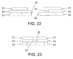
- the thickness of the pieces 18 is divided into three parts which can be equal or different.
- the upper third is referenced with number 21, the central one with number 22 and the lower with number 23.
- connection projections between pieces 18, made between the lower face 20 and which occupy the lower third 23, are referenced with the number 24 and are to be found on two adjacent sides and below the flange 25 which is continued along both adjacent or consecutive sides.
- the upper face of this flange is referenced with 26 and it shapes a ramp which facilitates the entrance of said flange 25 in the groove 27 of the respective opposite sides of the piece 18, as can be seen in the enlarged detail of figure 16.
- the coupling of two adjacent pieces is more clearly seen in figures 22 and 23, which respectively show the position before and after the coupling.
- the recesses corresponding to the projections 24 located on the respective opposite sides and also consecutive with each other are referenced with the number 28, and there exist four recesses 28 and a further four projections 24 in the contour of the pieces 18, in facing positions.
- the recesses are made in the edge of the flange 29 located in an extension of the lower third 23 of the thickness of the piece 18, in two of the corresponding consecutive sides, as is seen in the enlarged detail of figure 16 which corresponds to an elevation view of figure 15.
- the projections 24 and the complementary recesses 28 all have the shape of an obtuse angle triangle adopting an oblique arrangement in the same diagonal direction of the pieces 18, which means that the pieces can only be coupled in this diagonal direction since they enter perfectly centred. Both also have their edges rounded for that same purpose.
- clips 30 are located in the angular notches 31 of perpendicular sections 32 and 33 which, in the assembly of two pieces, shape the recipient housing for the clip 30, the angular notches 31 affecting solely the lower third 29 of the thickness of the piece.
- the sections 32 are made solely in two of the opposite sides of the pieces 18 and in proximity to the other two sides thereof.
- the sections 33 affect just the edge of the end zones of these same sides.
- one of the clips is already fitted and it can be seen how a blocking is produced in alignments of pieces in a linear composition, while in figure 24 an assembly can be seen following an intermeshed composition of the pieces 18.
- the central part of the clips 30 do not project from the edge from which the projections 24 emerge in order not to hinder the fitting of the other adjacent piece.
- the clips 30 have their arms slightly converging in order to facilitate the progressive insertion.
- the clips 30 on the sides of the recesses 28 are seated in a front or facing machining of the lower flange 29 which cuts the length of the tab precisely to the degree of the thickness of the central part of that clip 30.
- the parquet is formed as shown in figures 25 and 26 with two types of pieces in order to be able to produce intermeshed or herring-bone assemblies where some rectangular pieces, equal in their dimensions in this case, adopt an arrangement rotated 90° with respect to the one which has previously been laid.
- the pieces 34 offer the geometry shown in figures 27 to 31, and the pieces 35 that shown in figures 32 to 36.
- the pieces 34 and 35 are symmetric with respect to a vertical plane, in other words, they have mirror symmetry, as we will see further below.
- the pieces 34 present a visible or upper surface 36 with straight edges and a lower one 37 with some oblique projections 38 in two of their contiguous sides, and complementary oblique recesses 39 in the other two sides.
- the oblique projections 38 have a thickness corresponding to the lower third of the thickness of the pieces 34, and they are backed on below the paracentral flange 40 which emerges from the central zone of the thickness of the piece, in just two of these contiguous sides. In the other two opposite sides there exists a corresponding slot 41 which will receive the flange 40 in the tongue and groove coupling.
- the recesses 39 are made in the flange 42 which projects out in the lower third of the thickness of the pieces 34 being extended along the corresponding adjacent sides, these recesses being located below the paracentral flange 40 in the corresponding section in which they overlap when being laid and will in turn remain introduced in the recesses 39.
- the projections are oblique in the same way as the recesses, the coupling is carried out with a diagonal approach of the new piece to be laid.
- the pieces 35 possess the same geometrical characteristics in terms of flanges (40, 42), oblique recesses 39, oblique projections 38 and slots 41, but with all of them arranged symmetrically, as can be deduced from making a parallel comparison of figures 27, 28 and 30 of pieces 34, with 41, 42 and 44 of pieces 35.
Landscapes
- Engineering & Computer Science (AREA)
- Architecture (AREA)
- Civil Engineering (AREA)
- Structural Engineering (AREA)
- Floor Finish (AREA)
- Finishing Walls (AREA)
- Road Paving Structures (AREA)
Applications Claiming Priority (3)
| Application Number | Priority Date | Filing Date | Title |
|---|---|---|---|
| ES200601794A ES2322524B1 (es) | 2006-02-06 | 2006-02-06 | Dispositivo de union de placas o piezas tipo parquet. |
| ES200602066A ES2310100B1 (es) | 2006-07-31 | 2006-07-31 | Parquet. |
| ES200602092U ES1063793Y (es) | 2006-09-25 | 2006-09-25 | Parquet |
Publications (1)
| Publication Number | Publication Date |
|---|---|
| EP1816283A2 true EP1816283A2 (de) | 2007-08-08 |
Family
ID=38006830
Family Applications (1)
| Application Number | Title | Priority Date | Filing Date |
|---|---|---|---|
| EP07380022A Withdrawn EP1816283A2 (de) | 2006-02-06 | 2007-02-05 | Vorrichtung zum Verbinden von Parkettartige Platten oder -Stücke |
Country Status (8)
| Country | Link |
|---|---|
| US (1) | US20070214741A1 (de) |
| EP (1) | EP1816283A2 (de) |
| JP (1) | JP2007211584A (de) |
| KR (1) | KR20070080240A (de) |
| AU (1) | AU2007200499A1 (de) |
| BR (1) | BRPI0700232A (de) |
| CA (1) | CA2576889A1 (de) |
| MX (1) | MX2007001472A (de) |
Cited By (5)
| Publication number | Priority date | Publication date | Assignee | Title |
|---|---|---|---|---|
| WO2009044299A1 (en) * | 2007-10-04 | 2009-04-09 | Sepa S.R.L. | Flooring element for a modular floor, modular floor obtained therewith and method for assembling said modular floor |
| GB2454795A (en) * | 2007-11-14 | 2009-05-20 | Modular Arts Inc | Self-aligning modular, raised panel |
| FR2983891A1 (fr) * | 2011-12-07 | 2013-06-14 | Lay Thierry Le | Tapis parquet |
| IT201700115693A1 (it) * | 2017-10-13 | 2019-04-13 | Sepa Srl | Elemento di giunzione per pannelli per la realizzazione di pavimenti o pareti e sistema di realizzazione di pavimenti e pareti così ottenuto |
| WO2020159352A1 (en) * | 2019-01-30 | 2020-08-06 | Floor Locking Technology B.V. | Floor panel and floor covering |
Families Citing this family (46)
| Publication number | Priority date | Publication date | Assignee | Title |
|---|---|---|---|---|
| BRPI0308966B8 (pt) | 2002-04-03 | 2016-05-17 | Vaelinge Innovation Ab | tábua de assoalho |
| US7748177B2 (en) | 2004-02-25 | 2010-07-06 | Connor Sport Court International, Inc. | Modular tile with controlled deflection |
| US8397466B2 (en) | 2004-10-06 | 2013-03-19 | Connor Sport Court International, Llc | Tile with multiple-level surface |
| US8407951B2 (en) | 2004-10-06 | 2013-04-02 | Connor Sport Court International, Llc | Modular synthetic floor tile configured for enhanced performance |
| US7841144B2 (en) | 2005-03-30 | 2010-11-30 | Valinge Innovation Ab | Mechanical locking system for panels and method of installing same |
| USD656250S1 (en) | 2005-03-11 | 2012-03-20 | Connor Sport Court International, Llc | Tile with wide mouth coupling |
| SE533410C2 (sv) | 2006-07-11 | 2010-09-14 | Vaelinge Innovation Ab | Golvpaneler med mekaniska låssystem med en flexibel och förskjutbar tunga samt tunga därför |
| US7516587B2 (en) * | 2006-09-27 | 2009-04-14 | Barlow David R | Interlocking floor system |
| US8266857B2 (en) * | 2006-09-27 | 2012-09-18 | David Barlow R | Interlocking floor system with barbs for retaining covering |
| US11725394B2 (en) | 2006-11-15 | 2023-08-15 | Välinge Innovation AB | Mechanical locking of floor panels with vertical folding |
| US8689512B2 (en) | 2006-11-15 | 2014-04-08 | Valinge Innovation Ab | Mechanical locking of floor panels with vertical folding |
| SE531111C2 (sv) | 2006-12-08 | 2008-12-23 | Vaelinge Innovation Ab | Mekanisk låsning av golvpaneler |
| SG146580A1 (en) * | 2007-03-29 | 2008-10-30 | Promociones Brial S L | Assembly system for floor and/or wall tiles |
| WO2009116926A1 (en) | 2008-01-31 | 2009-09-24 | Välinge Innovation Belgium BVBA | Mechanical locking of floor panels, methods to install and uninstall panels, a method and an equipement to produce the locking system, a method to connect a displaceable tongue to a panel and a tongue blank |
| USD595431S1 (en) * | 2008-04-08 | 2009-06-30 | Monier Technical Centre Ltd. | Flat interlocking tile |
| SG172871A1 (en) * | 2009-01-30 | 2011-08-29 | Vaelinge Innovation Belgium Bvba | Mechanical lockings of floor panels and a tongue blank |
| CN101881076B (zh) * | 2010-06-09 | 2014-07-09 | 黄焕文 | 一种方便铺的组合式地板 |
| CN102695838B (zh) | 2010-01-12 | 2016-01-20 | 瓦林格创新股份有限公司 | 地板镶板的机械锁定系统 |
| US8683769B2 (en) | 2010-01-22 | 2014-04-01 | Connor Sport Court International, Llc | Modular sub-flooring system |
| US8881482B2 (en) | 2010-01-22 | 2014-11-11 | Connor Sport Court International, Llc | Modular flooring system |
| US8505256B2 (en) | 2010-01-29 | 2013-08-13 | Connor Sport Court International, Llc | Synthetic floor tile having partially-compliant support structure |
| BR112012018285B1 (pt) | 2010-02-04 | 2020-02-18 | Välinge Innovation AB | Conjunto de painéis de piso |
| UA114715C2 (uk) | 2011-07-05 | 2017-07-25 | Сералок Інновейшн Аб | Механічна фіксація панелей настилу підлоги до язичка з нанесеним шаром клею |
| US9725912B2 (en) | 2011-07-11 | 2017-08-08 | Ceraloc Innovation Ab | Mechanical locking system for floor panels |
| US8650826B2 (en) | 2011-07-19 | 2014-02-18 | Valinge Flooring Technology Ab | Mechanical locking system for floor panels |
| US8769905B2 (en) | 2011-08-15 | 2014-07-08 | Valinge Flooring Technology Ab | Mechanical locking system for floor panels |
| US8857126B2 (en) | 2011-08-15 | 2014-10-14 | Valinge Flooring Technology Ab | Mechanical locking system for floor panels |
| JP6313778B2 (ja) | 2012-11-22 | 2018-04-18 | セラロック、イノベーション、アクチボラグ | フロアパネルの機械的固定システム |
| US9194134B2 (en) | 2013-03-08 | 2015-11-24 | Valinge Innovation Ab | Building panels provided with a mechanical locking system |
| CA2913392C (en) | 2013-06-27 | 2022-01-18 | Valinge Innovation Ab | Building panel with a mechanical locking system |
| US9458634B2 (en) | 2014-05-14 | 2016-10-04 | Valinge Innovation Ab | Building panel with a mechanical locking system |
| US10246883B2 (en) | 2014-05-14 | 2019-04-02 | Valinge Innovation Ab | Building panel with a mechanical locking system |
| EP3868978B1 (de) | 2014-11-27 | 2025-05-21 | Välinge Innovation AB | Satz im wesentlichen identischer fussbodenpaneele mit mechanischem verriegelungssystem |
| US9951518B2 (en) * | 2015-03-31 | 2018-04-24 | Gestion Mcd Inc. | Tile system for suspended ceiling and wall, and method |
| US9631375B1 (en) | 2016-07-11 | 2017-04-25 | 308, Llc | Shock absorbing interlocking floor system |
| US10738484B2 (en) | 2016-07-11 | 2020-08-11 | 308, Llc | Shock absorbing interlocking floor system |
| US9874307B1 (en) * | 2016-07-13 | 2018-01-23 | Nestor Del Castillo | Portable stand system with two plaques |
| NL2020972B1 (en) | 2018-05-23 | 2019-12-02 | Innovations4Flooring Holding N V | Multi-purpose tile system, tile covering, and tile |
| CA3125895A1 (en) | 2019-01-10 | 2020-07-16 | Valinge Innovation Ab | Set of panels that can be vertically unlocked, a method and a device therefore |
| US12012755B2 (en) * | 2019-03-06 | 2024-06-18 | Armfoam Inc. | Tile system for ceiling and wall |
| CN212336618U (zh) * | 2020-07-08 | 2021-01-12 | 武汉枫叶通达汽保设备工具有限公司 | 一种拼接格栅块及洗车房拼接地板 |
| US20220064963A1 (en) * | 2020-08-26 | 2022-03-03 | Wearwell, Llc | Integrated mat assembly and method of use |
| CN113027097B (zh) * | 2021-03-23 | 2022-08-30 | 江苏广吴建设园林有限公司 | 一种异形拼花地砖铺设装置及铺设方法 |
| CN113502998A (zh) * | 2021-06-20 | 2021-10-15 | 郑素梅 | 分体式地板及其生产方法 |
| WO2023200367A1 (ru) * | 2022-04-12 | 2023-10-19 | Денис САГИДУЛЛИН | Светоотражающая декоративная панель |
| CN115126868A (zh) * | 2022-05-31 | 2022-09-30 | 中国北方发动机研究所(天津) | 一种拼接单元组合密封的装置及其加工方法 |
Family Cites Families (10)
| Publication number | Priority date | Publication date | Assignee | Title |
|---|---|---|---|---|
| US2189218A (en) * | 1937-12-06 | 1940-02-06 | Celotex Corp | Tiling |
| US3082488A (en) * | 1957-05-16 | 1963-03-26 | Nusbaum Mortimer | Floor or like tile |
| SE414067B (sv) * | 1977-03-30 | 1980-07-07 | Wicanders Korkfabriker Ab | Skivformigt golvelement med not- och spontpassning |
| US4426820A (en) * | 1979-04-24 | 1984-01-24 | Heinz Terbrack | Panel for a composite surface and a method of assembling same |
| SE514645C2 (sv) * | 1998-10-06 | 2001-03-26 | Perstorp Flooring Ab | Golvbeläggningsmaterial innefattande skivformiga golvelement avsedda att sammanfogas av separata sammanfogningsprofiler |
| US6332733B1 (en) * | 1999-12-23 | 2001-12-25 | Hamberger Industriewerke Gmbh | Joint |
| SE522860C2 (sv) * | 2000-03-10 | 2004-03-09 | Pergo Europ Ab | Vertikalt förenade golvelement innefattande en kombination av olika golvelement |
| US6684592B2 (en) * | 2001-08-13 | 2004-02-03 | Ron Martin | Interlocking floor panels |
| DE10159284B4 (de) * | 2001-12-04 | 2005-04-21 | Kronotec Ag | Gebäudeplatte, insbesondere Bodenpaneel |
| CN2764857Y (zh) * | 2005-02-28 | 2006-03-15 | 丹阳蓝客金刚石精密刀具有限公司 | 防断裂平装卡扣式地板拼块及其拼接的地板 |
-
2007
- 2007-02-05 CA CA002576889A patent/CA2576889A1/en not_active Abandoned
- 2007-02-05 EP EP07380022A patent/EP1816283A2/de not_active Withdrawn
- 2007-02-06 BR BRPI0700232-7A patent/BRPI0700232A/pt not_active Application Discontinuation
- 2007-02-06 JP JP2007026879A patent/JP2007211584A/ja active Pending
- 2007-02-06 KR KR1020070012383A patent/KR20070080240A/ko not_active Withdrawn
- 2007-02-06 MX MX2007001472A patent/MX2007001472A/es not_active Application Discontinuation
- 2007-02-06 AU AU2007200499A patent/AU2007200499A1/en not_active Abandoned
- 2007-02-06 US US11/702,604 patent/US20070214741A1/en not_active Abandoned
Cited By (8)
| Publication number | Priority date | Publication date | Assignee | Title |
|---|---|---|---|---|
| WO2009044299A1 (en) * | 2007-10-04 | 2009-04-09 | Sepa S.R.L. | Flooring element for a modular floor, modular floor obtained therewith and method for assembling said modular floor |
| CN101855411B (zh) * | 2007-10-04 | 2012-06-13 | 塞帕有限公司 | 用于模块化地板的地板元件、利用该地板元件获得的模块化地板及其组装方法 |
| US8596012B2 (en) | 2007-10-04 | 2013-12-03 | Sepa S.R.L. | Flooring element for a modular floor, modular floor obtained therewith and method for assembling modular floor |
| GB2454795A (en) * | 2007-11-14 | 2009-05-20 | Modular Arts Inc | Self-aligning modular, raised panel |
| FR2983891A1 (fr) * | 2011-12-07 | 2013-06-14 | Lay Thierry Le | Tapis parquet |
| IT201700115693A1 (it) * | 2017-10-13 | 2019-04-13 | Sepa Srl | Elemento di giunzione per pannelli per la realizzazione di pavimenti o pareti e sistema di realizzazione di pavimenti e pareti così ottenuto |
| WO2020159352A1 (en) * | 2019-01-30 | 2020-08-06 | Floor Locking Technology B.V. | Floor panel and floor covering |
| US11761215B2 (en) | 2019-01-30 | 2023-09-19 | 14F Licensing Nv | Floor panel and floor covering |
Also Published As
| Publication number | Publication date |
|---|---|
| CA2576889A1 (en) | 2007-08-06 |
| KR20070080240A (ko) | 2007-08-09 |
| JP2007211584A (ja) | 2007-08-23 |
| MX2007001472A (es) | 2009-02-12 |
| AU2007200499A1 (en) | 2007-08-23 |
| BRPI0700232A (pt) | 2007-11-06 |
| US20070214741A1 (en) | 2007-09-20 |
Similar Documents
| Publication | Publication Date | Title |
|---|---|---|
| US20070214741A1 (en) | Device for joining parquet-type plaques or pieces | |
| CA2283288C (en) | Building component structure, or building components | |
| US8544233B2 (en) | Building panels | |
| JP3570723B2 (ja) | 連結された複数のフォーム・パネルを使用する絶縁コンクリート型枠 | |
| CN103649437B (zh) | 用于地板镶板的机械锁定系统 | |
| US6546691B2 (en) | Method of laying panels | |
| US20030009971A1 (en) | Joining system and method for floor boards and boards therefor | |
| US8429869B2 (en) | Locking system and flooring board | |
| WO2000023674A9 (en) | Portable floor | |
| CA2627705C (en) | Assembly system for floor and/or wall tiles | |
| BRPI0718739A2 (pt) | " conjunto de painéis de assoalho providos com um sistema de travamento, método para instalar painéis de assoalho, método para desconectar painéis de assoalho e lingueta flexível para travamento vertical e horizontal de painéis de assoalho" | |
| US7003925B2 (en) | Locking system for floorboards | |
| EP2758608A1 (de) | Schräger mauerstein und wandabschnitt damit | |
| TWI412648B (zh) | 用於地板及/或牆面磁磚之裝配系統 | |
| CN101025043A (zh) | 用于连接镶木地板型饰板或部件的装置 | |
| JP7589165B2 (ja) | 結合要素と第1建築要素と建築パネルとを備えるセット、および前記セットを組み立てる方法 | |
| CN111433422B (zh) | 镶板和覆盖物 | |
| CN115726538A (zh) | 一种地板连接结构 | |
| EP1587998B1 (de) | Parkettplatte, die zur mechanischen verbindungsverriegelung mit entsprechenden parkettplatten angeordnet ist, und verfahren zur herstellung von parkettplatten | |
| AU2006213930A1 (en) | Floor covering |
Legal Events
| Date | Code | Title | Description |
|---|---|---|---|
| PUAI | Public reference made under article 153(3) epc to a published international application that has entered the european phase |
Free format text: ORIGINAL CODE: 0009012 |
|
| AK | Designated contracting states |
Kind code of ref document: A2 Designated state(s): AT BE BG CH CY CZ DE DK EE ES FI FR GB GR HU IE IS IT LI LT LU LV MC NL PL PT RO SE SI SK TR |
|
| AX | Request for extension of the european patent |
Extension state: AL BA HR MK YU |
|
| STAA | Information on the status of an ep patent application or granted ep patent |
Free format text: STATUS: THE APPLICATION IS DEEMED TO BE WITHDRAWN |
|
| 18D | Application deemed to be withdrawn |
Effective date: 20100901 |