EP1816312A2 - Sicherungsvorrichtung für Ausziehleitern - Google Patents
Sicherungsvorrichtung für Ausziehleitern Download PDFInfo
- Publication number
- EP1816312A2 EP1816312A2 EP06026778A EP06026778A EP1816312A2 EP 1816312 A2 EP1816312 A2 EP 1816312A2 EP 06026778 A EP06026778 A EP 06026778A EP 06026778 A EP06026778 A EP 06026778A EP 1816312 A2 EP1816312 A2 EP 1816312A2
- Authority
- EP
- European Patent Office
- Prior art keywords
- tubes
- ladder
- hole
- tube
- rung
- Prior art date
- Legal status (The legal status is an assumption and is not a legal conclusion. Google has not performed a legal analysis and makes no representation as to the accuracy of the status listed.)
- Granted
Links
Images





Classifications
-
- E—FIXED CONSTRUCTIONS
- E06—DOORS, WINDOWS, SHUTTERS, OR ROLLER BLINDS IN GENERAL; LADDERS
- E06C—LADDERS
- E06C1/00—Ladders in general
- E06C1/02—Ladders in general with rigid longitudinal member or members
- E06C1/04—Ladders for resting against objects, e.g. walls poles, trees
- E06C1/08—Ladders for resting against objects, e.g. walls poles, trees multi-part
- E06C1/12—Ladders for resting against objects, e.g. walls poles, trees multi-part extensible, e.g. telescopic
- E06C1/125—Ladders for resting against objects, e.g. walls poles, trees multi-part extensible, e.g. telescopic with tubular longitudinal members nested within each other
-
- E—FIXED CONSTRUCTIONS
- E06—DOORS, WINDOWS, SHUTTERS, OR ROLLER BLINDS IN GENERAL; LADDERS
- E06C—LADDERS
- E06C7/00—Component parts, supporting parts, or accessories
- E06C7/06—Securing devices or hooks for parts of extensible ladders
Definitions
- the present invention relates to an extending ladder which includes several rung units and each unit includes two buttons for releasing or securing the two columns relative to another rung unit.
- a conventional ladder includes two columns which are usually parallel to each other and rungs are connected between the two columns. The rungs are fixed to the columns so that the ladder is bulky and inconvenient for storage.
- Two extending ladders are known to applicant and disclosed in U.S. Patent No. 6,708,800 and U.S. Patent No. 6,883,645 .
- the two extending ladders require the user to push two thumbs toward a center portion of the ladder to extend or collapse the ladder. If the travel of the movement of the thumbs are too short, then the ladder cannot be extended or collapsed, and this is obviously inconvenient for the users.
- the present invention intends to provide a ladder that requires the user to push two buttons to release the interlocking between the rung units which are then easily extended or collapsed.
- the present invention relates to a ladder which comprises two parallel columns and each column is composed of a plurality of hollow tubes which have gradually reduced outer diameter so that the tubes with small sizes can be telescopically receivable in the tubes with large sizes.
- Each tube has an upper hole and a lower hole.
- Each pair of the tubes have a rung connected therebetween and two connectors are connected between two ends of the rung and the two tubes.
- Each connector has a mounting ring mounted on a top end of each tube and, an insertion inserted into one of the two ends of the rung.
- a connection member is connected between the mounting ring and the insertion.
- the connection member has a through hole is in alignment with the upper hole and communicates with the insertion and the mounting ring.
- Each insertion has a controller received therein and the controller including a seat and a button.
- the seat has a biasing member and a locking bar which is biased by the biasing member at one end thereof.
- the locking bar is inserted into the through hole of the connection member and the upper hole of the tube.
- a pin transversely extends through the locking bar.
- the button has a curved head and two tongues extend from an side of the head and extend into the insertion so as to push the locking bar.
- the rung has two apertures defined in a side of two ends thereof and the insertions are inserted into the two ends of the rung so that when the locking bars extend through the through holes of the connectors, the upper holes of the two tubes with large size and the lower holes of the tubes with small size, the ladder is extended and established.
- the buttons are pushed, tongues shift the pins such that the locking bars are withdrawn from the lower holes of the tubes with small size, and the tubes with small sizes are telescopically received in the tubes of large sizes.
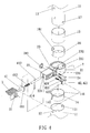
- the ladder of the present invention is composed of composed of a plurality of rung units and each rung unit includes two hollow tubes 11 and a rung 3 connected therebetween.
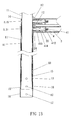
- the hollow tubes 11 form two parallel columns 1 and the hollow tubes 11 have gradually reduced outer diameter so that the tubes 11 with small sizes are telescopically receivable in the tubes 11 with large sizes as shown in Fig. 1.
- Each tube 11 has an upper hole 12 and a lower hole 13 defined through a wall of two ends thereof, and the upper holes 12 and the lower holes 13 in the two respective tubes 11 face each other.
- Two connectors 2 are connected between two ends of the rung 3 and the two tubes 11.
- a separation bar 18 is connected between the two tubes 11 with largest sizes to keep a stable width between the two columns 1.
- Each connector 2 has a mounting ring 21 and an insertion 22, wherein the mounting ring 21 is mounted on a top end of each tube 11 and the insertion 22 is inserted into one of the two ends of the rung 3.
- a connection member 23 is connected between the mounting ring 21 and the insertion 22.
- a through hole 231 is defined in the connection member 23 and in alignment with the upper hole 12 so as to communicate with the insertion 22 and the mounting ring 21.
- the connection member 23 has an L-shaped slot 232 which communicates with the mounting ring 21.
- Two passages 233 are defined through the connection member 23 such that the through hole 231 is located between the two passages 233.
- Two bolts 24 extend through the passages 233 and are connected to a reinforcement plate 241 so that the mounting ring 21 is fixed on the tube 11.
- Each of the tubes 11 has a positioning hole 121 located close to the top end thereof and the mounting ring 21 has a positioning protrusion 211 extending from an inner periphery thereof so that the positioning protrusion
- each of the tubes 11 has an inner bush 14 inserted in a top end thereof and the inner bush 14 has a flange 141 extending radially outward therefrom so as to be positioned between the mounting ring 21 and the tube 11.
- the inner bush 14 has a notch 142 which is in alignment with the upper hole 12.
- Each of the tubes 11 has an outer bush 15 and an outer collar 16 mounted to an outer periphery of a lower end of the tube 11.
- the outer bush 15 and the outer collar 16 are located between the tube 11 with small size and the tube 11 with large size, and do not block the lower hole 13.
- Each of the tubes 11 has an engaging hole 17 defined through a wall of the lower end thereof and the outer bush 16 has a boss 161 extending from an inner periphery thereof. The boss 161 is engaged with the engaging hole 17 such that the outer bush 16 is fixed on the tube 11.
- Each insertion 22 has a controller 4 received therein and the controller 4 includes a seat 41 and a button 42.
- the seat 41 includes a board 411, a biasing member 412 received in a box on the board 411 and a locking bar 413 which has one end inserted in the box via an open end of the box and is biased by the biasing member 412 at one end thereof.
- the board 411 can be inserted in a groove 211 defined in an underside of the insertion 22 so as to be securely connected to the insertion 22.
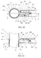
- the locking bar 413 is inserted into the through hole 231 of the connection member 23 and the upper hole 12 of the tube 11.
- a pin 414 transversely extends through the locking bar 413.
- the button 42 has a curved head 421 which has a stepped surface 422 and two tongues 423 extend from an side of the head 421 and into the insertion 22.
- Each of the tongues 423 has an inclined section which pushes the locking bar 413 when the button 42 is pushed.
- the rung 3 has two apertures 31 defined in a side of two ends thereof and the insertions 22 are inserted into the two ends of the rung 3 and the heads 421 project from the apertures 31.
- the stepped surface 422 of each button 42 is engaged with an inside of the aperture 31 corresponding thereto.
- the ladder can be easily collapsed or extended by pushing the two buttons 42 to move the locking bars 413.
- the tubes 11 can be made by a first material, and the inner bushes 14, the outer bushes 15 and the outer collars 16 can be made by a second material.
- the first material can be aluminum alloy and the second material can be composite material.
Landscapes
- Engineering & Computer Science (AREA)
- Mechanical Engineering (AREA)
- Ladders (AREA)
- Programmable Controllers (AREA)
Applications Claiming Priority (1)
| Application Number | Priority Date | Filing Date | Title |
|---|---|---|---|
| CNU2006200015385U CN2876303Y (zh) | 2006-02-07 | 2006-02-07 | 按压式伸缩梯 |
Publications (3)
| Publication Number | Publication Date |
|---|---|
| EP1816312A2 true EP1816312A2 (de) | 2007-08-08 |
| EP1816312A3 EP1816312A3 (de) | 2009-03-18 |
| EP1816312B1 EP1816312B1 (de) | 2010-04-14 |
Family
ID=37819540
Family Applications (1)
| Application Number | Title | Priority Date | Filing Date |
|---|---|---|---|
| EP06026778A Not-in-force EP1816312B1 (de) | 2006-02-07 | 2006-12-22 | Sicherungsvorrichtung für Ausziehleitern |
Country Status (4)
| Country | Link |
|---|---|
| EP (1) | EP1816312B1 (de) |
| CN (1) | CN2876303Y (de) |
| AT (1) | ATE464454T1 (de) |
| DE (1) | DE602006013589D1 (de) |
Cited By (4)
| Publication number | Priority date | Publication date | Assignee | Title |
|---|---|---|---|---|
| EP2740879A3 (de) * | 2008-08-22 | 2016-11-09 | Core Distribution Inc. | Aus- und einziehbare Leiter |
| US10731413B2 (en) | 2014-12-02 | 2020-08-04 | Core Distribution, Inc. | Foldable ladder |
| US11174678B2 (en) | 2017-11-08 | 2021-11-16 | Core Distribution, Inc. | Locking assembly for a telescoping ladder |
| US11795760B2 (en) | 2019-10-24 | 2023-10-24 | Core Distribution, Inc. | Ladder tripod assembly and system |
Families Citing this family (2)
| Publication number | Priority date | Publication date | Assignee | Title |
|---|---|---|---|---|
| WO2010034135A1 (zh) * | 2008-09-25 | 2010-04-01 | Kuo Chingyao | 伸缩梯 |
| CN109826554A (zh) * | 2019-04-08 | 2019-05-31 | 黄崇华 | 伸缩梯 |
Family Cites Families (3)
| Publication number | Priority date | Publication date | Assignee | Title |
|---|---|---|---|---|
| SE523253C2 (sv) * | 2001-06-13 | 2004-04-06 | Telesteps Ab | Hopfällbar stege |
| US6708800B2 (en) * | 2002-08-02 | 2004-03-23 | Core Distribution, Inc. | Extending ladder and associated manufacturing methods |
| CN2674056Y (zh) * | 2003-12-03 | 2005-01-26 | 郭晶耀 | 伸缩梯结构 |
-
2006
- 2006-02-07 CN CNU2006200015385U patent/CN2876303Y/zh not_active Expired - Fee Related
- 2006-12-22 EP EP06026778A patent/EP1816312B1/de not_active Not-in-force
- 2006-12-22 AT AT06026778T patent/ATE464454T1/de not_active IP Right Cessation
- 2006-12-22 DE DE602006013589T patent/DE602006013589D1/de active Active
Cited By (7)
| Publication number | Priority date | Publication date | Assignee | Title |
|---|---|---|---|---|
| EP2740879A3 (de) * | 2008-08-22 | 2016-11-09 | Core Distribution Inc. | Aus- und einziehbare Leiter |
| US10053912B2 (en) | 2008-08-22 | 2018-08-21 | Core Distribution, Inc. | Extendable / retractable ladder |
| EP3444425A1 (de) * | 2008-08-22 | 2019-02-20 | Core Distribution Inc. | Aus- und einziehbare leiter |
| US10753149B2 (en) | 2008-08-22 | 2020-08-25 | Core Distribution, Inc. | Extendable / retractable ladder |
| US10731413B2 (en) | 2014-12-02 | 2020-08-04 | Core Distribution, Inc. | Foldable ladder |
| US11174678B2 (en) | 2017-11-08 | 2021-11-16 | Core Distribution, Inc. | Locking assembly for a telescoping ladder |
| US11795760B2 (en) | 2019-10-24 | 2023-10-24 | Core Distribution, Inc. | Ladder tripod assembly and system |
Also Published As
| Publication number | Publication date |
|---|---|
| EP1816312B1 (de) | 2010-04-14 |
| CN2876303Y (zh) | 2007-03-07 |
| DE602006013589D1 (de) | 2010-05-27 |
| ATE464454T1 (de) | 2010-04-15 |
| EP1816312A3 (de) | 2009-03-18 |
Similar Documents
| Publication | Publication Date | Title |
|---|---|---|
| US20070209875A1 (en) | Securing device for extending ladder | |
| US20100270106A1 (en) | Securing device for extending ladder | |
| US7686323B2 (en) | Baby stroller with portable cradle | |
| US6357080B1 (en) | Multi-sections retractable handle | |
| US6371873B1 (en) | Goal assembly | |
| EP3444425B1 (de) | Aus- und einziehbare leiter | |
| US6752729B1 (en) | Connection member for connecting parts of frame assembly | |
| US20080042383A1 (en) | Front wheel assembly for baby strollers | |
| US8387753B2 (en) | Ergonomic extendable/retractable ladder | |
| US8622175B2 (en) | Collapsible ladder | |
| CN101472409A (zh) | 电子装置壳体 | |
| US20040129472A1 (en) | Electric vehicle handle collapsing device | |
| EP1816312B1 (de) | Sicherungsvorrichtung für Ausziehleitern | |
| US7434844B2 (en) | Quick release pipe connection | |
| US20060051159A1 (en) | Positioning device for a foldable structure | |
| US6171099B1 (en) | Switch safety device for a gas torch | |
| US20090049950A1 (en) | Pedal adjustable device for exercisers | |
| US20060144206A1 (en) | Punch structure | |
| US4687076A (en) | Segment connector for modular ladder | |
| US6226834B1 (en) | Handle structure for a luggage | |
| US20030132180A1 (en) | Display rack for roller board | |
| EP1656855B1 (de) | Ein Stuhl | |
| US20040004332A1 (en) | Caster receiving device for luggage | |
| US20030015641A1 (en) | Telescopic boom for use in model building | |
| EP2042404B1 (de) | Kinderwagen mit tragbarer Wiege |
Legal Events
| Date | Code | Title | Description |
|---|---|---|---|
| PUAI | Public reference made under article 153(3) epc to a published international application that has entered the european phase |
Free format text: ORIGINAL CODE: 0009012 |
|
| AK | Designated contracting states |
Kind code of ref document: A2 Designated state(s): AT BE BG CH CY CZ DE DK EE ES FI FR GB GR HU IE IS IT LI LT LU LV MC NL PL PT RO SE SI SK TR |
|
| AX | Request for extension of the european patent |
Extension state: AL BA HR MK YU |
|
| PUAL | Search report despatched |
Free format text: ORIGINAL CODE: 0009013 |
|
| AK | Designated contracting states |
Kind code of ref document: A3 Designated state(s): AT BE BG CH CY CZ DE DK EE ES FI FR GB GR HU IE IS IT LI LT LU LV MC NL PL PT RO SE SI SK TR |
|
| AX | Request for extension of the european patent |
Extension state: AL BA HR MK RS |
|
| RIC1 | Information provided on ipc code assigned before grant |
Ipc: E06C 7/06 20060101ALI20090212BHEP Ipc: E06C 1/12 20060101AFI20070510BHEP |
|
| 17P | Request for examination filed |
Effective date: 20090319 |
|
| 17Q | First examination report despatched |
Effective date: 20090602 |
|
| GRAP | Despatch of communication of intention to grant a patent |
Free format text: ORIGINAL CODE: EPIDOSNIGR1 |
|
| AKX | Designation fees paid |
Designated state(s): AT BE BG CH CY CZ DE DK EE ES FI FR GB GR HU IE IS IT LI LT LU LV MC NL PL PT RO SE SI SK TR |
|
| GRAS | Grant fee paid |
Free format text: ORIGINAL CODE: EPIDOSNIGR3 |
|
| GRAL | Information related to payment of fee for publishing/printing deleted |
Free format text: ORIGINAL CODE: EPIDOSDIGR3 |
|
| GRAS | Grant fee paid |
Free format text: ORIGINAL CODE: EPIDOSNIGR3 |
|
| GRAA | (expected) grant |
Free format text: ORIGINAL CODE: 0009210 |
|
| AK | Designated contracting states |
Kind code of ref document: B1 Designated state(s): AT BE BG CH CY CZ DE DK EE ES FI FR GB GR HU IE IS IT LI LT LU LV MC NL PL PT RO SE SI SK TR |
|
| REG | Reference to a national code |
Ref country code: GB Ref legal event code: FG4D |
|
| REG | Reference to a national code |
Ref country code: CH Ref legal event code: EP |
|
| REG | Reference to a national code |
Ref country code: IE Ref legal event code: FG4D |
|
| REF | Corresponds to: |
Ref document number: 602006013589 Country of ref document: DE Date of ref document: 20100527 Kind code of ref document: P |
|
| REG | Reference to a national code |
Ref country code: NL Ref legal event code: VDEP Effective date: 20100414 |
|
| LTIE | Lt: invalidation of european patent or patent extension |
Effective date: 20100414 |
|
| PG25 | Lapsed in a contracting state [announced via postgrant information from national office to epo] |
Ref country code: ES Free format text: LAPSE BECAUSE OF FAILURE TO SUBMIT A TRANSLATION OF THE DESCRIPTION OR TO PAY THE FEE WITHIN THE PRESCRIBED TIME-LIMIT Effective date: 20100725 Ref country code: SE Free format text: LAPSE BECAUSE OF FAILURE TO SUBMIT A TRANSLATION OF THE DESCRIPTION OR TO PAY THE FEE WITHIN THE PRESCRIBED TIME-LIMIT Effective date: 20100414 Ref country code: NL Free format text: LAPSE BECAUSE OF FAILURE TO SUBMIT A TRANSLATION OF THE DESCRIPTION OR TO PAY THE FEE WITHIN THE PRESCRIBED TIME-LIMIT Effective date: 20100414 Ref country code: LT Free format text: LAPSE BECAUSE OF FAILURE TO SUBMIT A TRANSLATION OF THE DESCRIPTION OR TO PAY THE FEE WITHIN THE PRESCRIBED TIME-LIMIT Effective date: 20100414 |
|
| PG25 | Lapsed in a contracting state [announced via postgrant information from national office to epo] |
Ref country code: AT Free format text: LAPSE BECAUSE OF FAILURE TO SUBMIT A TRANSLATION OF THE DESCRIPTION OR TO PAY THE FEE WITHIN THE PRESCRIBED TIME-LIMIT Effective date: 20100414 Ref country code: IS Free format text: LAPSE BECAUSE OF FAILURE TO SUBMIT A TRANSLATION OF THE DESCRIPTION OR TO PAY THE FEE WITHIN THE PRESCRIBED TIME-LIMIT Effective date: 20100814 Ref country code: LV Free format text: LAPSE BECAUSE OF FAILURE TO SUBMIT A TRANSLATION OF THE DESCRIPTION OR TO PAY THE FEE WITHIN THE PRESCRIBED TIME-LIMIT Effective date: 20100414 Ref country code: SI Free format text: LAPSE BECAUSE OF FAILURE TO SUBMIT A TRANSLATION OF THE DESCRIPTION OR TO PAY THE FEE WITHIN THE PRESCRIBED TIME-LIMIT Effective date: 20100414 Ref country code: FI Free format text: LAPSE BECAUSE OF FAILURE TO SUBMIT A TRANSLATION OF THE DESCRIPTION OR TO PAY THE FEE WITHIN THE PRESCRIBED TIME-LIMIT Effective date: 20100414 |
|
| PG25 | Lapsed in a contracting state [announced via postgrant information from national office to epo] |
Ref country code: CY Free format text: LAPSE BECAUSE OF FAILURE TO SUBMIT A TRANSLATION OF THE DESCRIPTION OR TO PAY THE FEE WITHIN THE PRESCRIBED TIME-LIMIT Effective date: 20100512 Ref country code: GR Free format text: LAPSE BECAUSE OF FAILURE TO SUBMIT A TRANSLATION OF THE DESCRIPTION OR TO PAY THE FEE WITHIN THE PRESCRIBED TIME-LIMIT Effective date: 20100715 Ref country code: PL Free format text: LAPSE BECAUSE OF FAILURE TO SUBMIT A TRANSLATION OF THE DESCRIPTION OR TO PAY THE FEE WITHIN THE PRESCRIBED TIME-LIMIT Effective date: 20100414 |
|
| PG25 | Lapsed in a contracting state [announced via postgrant information from national office to epo] |
Ref country code: PT Free format text: LAPSE BECAUSE OF FAILURE TO SUBMIT A TRANSLATION OF THE DESCRIPTION OR TO PAY THE FEE WITHIN THE PRESCRIBED TIME-LIMIT Effective date: 20100816 Ref country code: EE Free format text: LAPSE BECAUSE OF FAILURE TO SUBMIT A TRANSLATION OF THE DESCRIPTION OR TO PAY THE FEE WITHIN THE PRESCRIBED TIME-LIMIT Effective date: 20100414 Ref country code: DK Free format text: LAPSE BECAUSE OF FAILURE TO SUBMIT A TRANSLATION OF THE DESCRIPTION OR TO PAY THE FEE WITHIN THE PRESCRIBED TIME-LIMIT Effective date: 20100414 |
|
| PLBE | No opposition filed within time limit |
Free format text: ORIGINAL CODE: 0009261 |
|
| STAA | Information on the status of an ep patent application or granted ep patent |
Free format text: STATUS: NO OPPOSITION FILED WITHIN TIME LIMIT |
|
| PG25 | Lapsed in a contracting state [announced via postgrant information from national office to epo] |
Ref country code: RO Free format text: LAPSE BECAUSE OF FAILURE TO SUBMIT A TRANSLATION OF THE DESCRIPTION OR TO PAY THE FEE WITHIN THE PRESCRIBED TIME-LIMIT Effective date: 20100414 Ref country code: BE Free format text: LAPSE BECAUSE OF FAILURE TO SUBMIT A TRANSLATION OF THE DESCRIPTION OR TO PAY THE FEE WITHIN THE PRESCRIBED TIME-LIMIT Effective date: 20100414 Ref country code: CZ Free format text: LAPSE BECAUSE OF FAILURE TO SUBMIT A TRANSLATION OF THE DESCRIPTION OR TO PAY THE FEE WITHIN THE PRESCRIBED TIME-LIMIT Effective date: 20100414 Ref country code: SK Free format text: LAPSE BECAUSE OF FAILURE TO SUBMIT A TRANSLATION OF THE DESCRIPTION OR TO PAY THE FEE WITHIN THE PRESCRIBED TIME-LIMIT Effective date: 20100414 |
|
| 26N | No opposition filed |
Effective date: 20110117 |
|
| PG25 | Lapsed in a contracting state [announced via postgrant information from national office to epo] |
Ref country code: IT Free format text: LAPSE BECAUSE OF FAILURE TO SUBMIT A TRANSLATION OF THE DESCRIPTION OR TO PAY THE FEE WITHIN THE PRESCRIBED TIME-LIMIT Effective date: 20100414 |
|
| PG25 | Lapsed in a contracting state [announced via postgrant information from national office to epo] |
Ref country code: MC Free format text: LAPSE BECAUSE OF NON-PAYMENT OF DUE FEES Effective date: 20101231 |
|
| REG | Reference to a national code |
Ref country code: CH Ref legal event code: PL |
|
| REG | Reference to a national code |
Ref country code: FR Ref legal event code: ST Effective date: 20110831 |
|
| PG25 | Lapsed in a contracting state [announced via postgrant information from national office to epo] |
Ref country code: CH Free format text: LAPSE BECAUSE OF NON-PAYMENT OF DUE FEES Effective date: 20101231 Ref country code: LI Free format text: LAPSE BECAUSE OF NON-PAYMENT OF DUE FEES Effective date: 20101231 Ref country code: IE Free format text: LAPSE BECAUSE OF NON-PAYMENT OF DUE FEES Effective date: 20101222 Ref country code: FR Free format text: LAPSE BECAUSE OF NON-PAYMENT OF DUE FEES Effective date: 20110103 |
|
| PG25 | Lapsed in a contracting state [announced via postgrant information from national office to epo] |
Ref country code: LU Free format text: LAPSE BECAUSE OF NON-PAYMENT OF DUE FEES Effective date: 20101222 Ref country code: BG Free format text: LAPSE BECAUSE OF FAILURE TO SUBMIT A TRANSLATION OF THE DESCRIPTION OR TO PAY THE FEE WITHIN THE PRESCRIBED TIME-LIMIT Effective date: 20100414 Ref country code: HU Free format text: LAPSE BECAUSE OF FAILURE TO SUBMIT A TRANSLATION OF THE DESCRIPTION OR TO PAY THE FEE WITHIN THE PRESCRIBED TIME-LIMIT Effective date: 20101015 |
|
| PG25 | Lapsed in a contracting state [announced via postgrant information from national office to epo] |
Ref country code: TR Free format text: LAPSE BECAUSE OF FAILURE TO SUBMIT A TRANSLATION OF THE DESCRIPTION OR TO PAY THE FEE WITHIN THE PRESCRIBED TIME-LIMIT Effective date: 20100414 |
|
| PGFP | Annual fee paid to national office [announced via postgrant information from national office to epo] |
Ref country code: GB Payment date: 20121107 Year of fee payment: 7 |
|
| PGFP | Annual fee paid to national office [announced via postgrant information from national office to epo] |
Ref country code: DE Payment date: 20121231 Year of fee payment: 7 |
|
| PG25 | Lapsed in a contracting state [announced via postgrant information from national office to epo] |
Ref country code: BG Free format text: LAPSE BECAUSE OF FAILURE TO SUBMIT A TRANSLATION OF THE DESCRIPTION OR TO PAY THE FEE WITHIN THE PRESCRIBED TIME-LIMIT Effective date: 20100714 |
|
| REG | Reference to a national code |
Ref country code: DE Ref legal event code: R119 Ref document number: 602006013589 Country of ref document: DE |
|
| GBPC | Gb: european patent ceased through non-payment of renewal fee |
Effective date: 20131222 |
|
| REG | Reference to a national code |
Ref country code: DE Ref legal event code: R119 Ref document number: 602006013589 Country of ref document: DE Effective date: 20140701 |
|
| PG25 | Lapsed in a contracting state [announced via postgrant information from national office to epo] |
Ref country code: DE Free format text: LAPSE BECAUSE OF NON-PAYMENT OF DUE FEES Effective date: 20140701 |
|
| PG25 | Lapsed in a contracting state [announced via postgrant information from national office to epo] |
Ref country code: GB Free format text: LAPSE BECAUSE OF NON-PAYMENT OF DUE FEES Effective date: 20131222 |