EP1816408B1 - Klimatisierungsvorrichtung mit freier Kühlung - Google Patents
Klimatisierungsvorrichtung mit freier Kühlung Download PDFInfo
- Publication number
- EP1816408B1 EP1816408B1 EP07100880A EP07100880A EP1816408B1 EP 1816408 B1 EP1816408 B1 EP 1816408B1 EP 07100880 A EP07100880 A EP 07100880A EP 07100880 A EP07100880 A EP 07100880A EP 1816408 B1 EP1816408 B1 EP 1816408B1
- Authority
- EP
- European Patent Office
- Prior art keywords
- fan
- air
- shutter
- ports
- open
- Prior art date
- Legal status (The legal status is an assumption and is not a legal conclusion. Google has not performed a legal analysis and makes no representation as to the accuracy of the status listed.)
- Not-in-force
Links
- 238000001816 cooling Methods 0.000 title claims abstract description 56
- 230000003750 conditioning effect Effects 0.000 title claims abstract description 40
- 239000003570 air Substances 0.000 claims abstract description 72
- 238000005057 refrigeration Methods 0.000 claims abstract description 22
- 239000012080 ambient air Substances 0.000 claims abstract description 16
- 238000011144 upstream manufacturing Methods 0.000 claims abstract description 7
- 230000003213 activating effect Effects 0.000 description 2
- 238000005516 engineering process Methods 0.000 description 2
- 230000000670 limiting effect Effects 0.000 description 2
- 238000004378 air conditioning Methods 0.000 description 1
- 239000000463 material Substances 0.000 description 1
- 230000007704 transition Effects 0.000 description 1
Images

Classifications
-
- F—MECHANICAL ENGINEERING; LIGHTING; HEATING; WEAPONS; BLASTING
- F24—HEATING; RANGES; VENTILATING
- F24F—AIR-CONDITIONING; AIR-HUMIDIFICATION; VENTILATION; USE OF AIR CURRENTS FOR SCREENING
- F24F1/00—Room units for air-conditioning, e.g. separate or self-contained units or units receiving primary air from a central station
- F24F1/02—Self-contained room units for air-conditioning, i.e. with all apparatus for treatment installed in a common casing
- F24F1/022—Self-contained room units for air-conditioning, i.e. with all apparatus for treatment installed in a common casing comprising a compressor cycle
- F24F1/027—Self-contained room units for air-conditioning, i.e. with all apparatus for treatment installed in a common casing comprising a compressor cycle mounted in wall openings, e.g. in windows
-
- F—MECHANICAL ENGINEERING; LIGHTING; HEATING; WEAPONS; BLASTING
- F24—HEATING; RANGES; VENTILATING
- F24F—AIR-CONDITIONING; AIR-HUMIDIFICATION; VENTILATION; USE OF AIR CURRENTS FOR SCREENING
- F24F12/00—Use of energy recovery systems in air conditioning, ventilation or screening
-
- F—MECHANICAL ENGINEERING; LIGHTING; HEATING; WEAPONS; BLASTING
- F24—HEATING; RANGES; VENTILATING
- F24F—AIR-CONDITIONING; AIR-HUMIDIFICATION; VENTILATION; USE OF AIR CURRENTS FOR SCREENING
- F24F11/00—Control or safety arrangements
- F24F11/0001—Control or safety arrangements for ventilation
- F24F2011/0006—Control or safety arrangements for ventilation using low temperature external supply air to assist cooling
-
- Y—GENERAL TAGGING OF NEW TECHNOLOGICAL DEVELOPMENTS; GENERAL TAGGING OF CROSS-SECTIONAL TECHNOLOGIES SPANNING OVER SEVERAL SECTIONS OF THE IPC; TECHNICAL SUBJECTS COVERED BY FORMER USPC CROSS-REFERENCE ART COLLECTIONS [XRACs] AND DIGESTS
- Y02—TECHNOLOGIES OR APPLICATIONS FOR MITIGATION OR ADAPTATION AGAINST CLIMATE CHANGE
- Y02B—CLIMATE CHANGE MITIGATION TECHNOLOGIES RELATED TO BUILDINGS, e.g. HOUSING, HOUSE APPLIANCES OR RELATED END-USER APPLICATIONS
- Y02B30/00—Energy efficient heating, ventilation or air conditioning [HVAC]
- Y02B30/54—Free-cooling systems
Definitions
- the present invention relates to a conditioning device of the free cooling type.
- Air conditioning devices provided with the option known as "free cooling" are currently known in the field of climate control of enclosed spaces ranging from industrial facilities to telephone exchanges to offices to private dwellings and the like.
- the free cooling option is based on the ability of the climate control unit to use, for the conditioning of an enclosed space, air which arrives from outside when said air has an enthalpy value which is higher than that of the air of the internal space.
- Free cooling allows considerable energy saving on the part of the user as well as a healthier management of the air of the internal space, which is replaced appropriately by activating free cooling.
- Known types of free cooling conditioning device are generally installed externally or are wall-mounted with respect to the walls which form the space to be climate-controlled.
- the refrigeration circuit In the first conditioning mode, the refrigeration circuit is active, the shutter closes a first port for aspirating air from outside and opens a second port for aspirating air from the enclosed space, forming a first intake channel which connects said second port to the first fan, from which the air reaches the evaporator and from there returns to the space to be climate-controlled.
- the second fan also is active and aspirates air from outside in order to send it to the condenser of the refrigeration circuit.
- the transition from this first mode to the second free cooling operating mode occurs by tilting the shutter, which is arranged in a second configuration which is adapted to close the first intake channel between the second port, which is open onto the inside environment, and the first fan, and to open a second channel between a third port, which is open onto the outside, and the first fan, and a third channel between the second port and a fourth port, which also is open onto the outside.
- the second fan In this second operating mode, the second fan is off, the refrigeration circuit is inactive, warm air flows from the internal environment outward through the third channel, and the fan aspirates cool air from the outside in order to introduce it into the environment by means of the second channel.
- a cooling device having the features set forth in preamble of claim 1 known from US 2004/0148948 A1 .
- the aim of the present invention is to provide a conditioning device of the free cooling type which is capable of obviating the drawbacks revealed by known types.
- an object of the present invention is to provide a conditioning device which is capable of increasing the efficiency and effectiveness of the free cooling operating mode.
- Another object of the present invention is to provide a conditioning device which is not less compact than known types of device.
- Another object of the present invention is to provide a conditioning device of the free cooling type which can be manufactured cheaply with known systems and technologies.
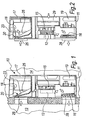
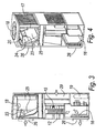
- a conditioning device of the free cooling type according to the invention is generally designated by the reference numeral 10.
- the conditioning device 10 comprises, within a box-like containment body 11:
- the first shutter 15 is of the type with baskets, shown schematically in Figure 5 and constituted by a first basket 21 and by at least one complementarily shaped second basket 22 inserted within it.
- the first basket 21 opens onto the first fan 12 and is provided with first front ports 21a on its bottom and second lateral ports 21 b on its lateral surface.
- the second basket 22 which is internal and is a single one in the embodiment of the invention described here, forms the flow control means of the first shutter 15, by being connected to rotation means for rotation with respect to the first basket 21 and by being contoured so that portions of its bottom and its lateral surface alternately block the first front ports 21a and the second lateral ports 21b; the second basket 22 can be actuated so as to provide selectively one of the following three configurations:
- the first configuration allows the operation of the device 10 in the first mode for cooling with ambient air recirculation and active refrigeration circuit.
- the second configuration is designed for the operation of the device 10 in the second free cooling mode, by connecting the outside to the first fan 12.
- the second shutter 20 is provided by a louver 23, which is arranged so as to open/close a corresponding opening 24 which is formed on a redirection wall 25 which is arranged in front of a first port 26 for the outflow of air from the enclosed space 13.
- the redirection wall 25 is inclined so that when the opening 24 is closed the air is redirected toward the first shutter 15 and the first fan 12, as shown by way of example in Figure 1 .
- louver 23 If the louver 23 is open, the internal air can pass through the opening 24 and flow out through the second fan 18.
- the louver 23 is actuated by electromechanical movement means, not shown for the sake of simplicity, which are actuated by an electronic control unit, which also manages the first shutter 15 and the two fans 12 and 18.
- the device 10 according to the invention is therefore capable of operating in three modes.
- This third mode therefore allows to obviate the drawback of known types of device, since thanks to the opening 24 which connects the first port 26 (for the outflow of the air from the enclosed space 13) to the second fan 18, it is able to increase the efficiency and effectiveness of the free cooling operating mode, simply by activating the second fan 18 with the refrigeration circuit off.
- the second fan 18 is adapted to aspirate air from the enclosed space 13, accelerating its replacement.
- the device 10 which differently from known types of device has the port for the outflow of air from the enclosed space, i.e., the first port 26, connected by means of the second shutter 20 to the air passage chamber to which both the condenser 17 and the second fan 18 lead.
- the present invention provides a conditioning device which is capable of increasing the efficiency and effectiveness of the free cooling operating mode with respect to known devices.
- the present invention provides a conditioning device which is not less compact than known types of device.
- the present invention provides a conditioning device of the free cooling type which can be manufactured cheaply with known systems and technologies.
- the materials employed may be any according to requirements and to the state of the art.
Landscapes
- Engineering & Computer Science (AREA)
- Chemical & Material Sciences (AREA)
- Combustion & Propulsion (AREA)
- Mechanical Engineering (AREA)
- General Engineering & Computer Science (AREA)
- Air Conditioning Control Device (AREA)
- Air-Conditioning Room Units, And Self-Contained Units In General (AREA)
- Devices For Blowing Cold Air, Devices For Blowing Warm Air, And Means For Preventing Water Condensation In Air Conditioning Units (AREA)
- Devices That Are Associated With Refrigeration Equipment (AREA)
- Details Of Measuring And Other Instruments (AREA)
Claims (11)
- Eine Klimatisierungsvorrichtung mit freier Kühlung, die innerhalb eines kastenähnlichen Einschlusskörpers (11) Folgendes umfasst:- einen ersten Hauptventilator (12) zum Ansaugen von Luft aus einem geschlossenen Raum (13) oder von außen (14),- einen Verdunster (16), der von angesaugter Luft, die in den zu klimatisierenden geschlossenen Raum (13) eingeführt werden soll, erreicht wird,- einen Kondensator (17), der mit dem Verdunster (16) verküpft ist,- einen zweiten Ventilator (18) für die Strömung von Luft über den Kondensator (17),- einen Kompressor (19), der mit dem Kondensator (17) und dem Verdunster (16) verknüpft ist, um einen Kühlkreislauf zum Kühlen der angesaugten Luft zu bilden,- eine erste Klappe (15), die stromaufwärts vom ersten Ventilator (12) angeordnet ist, zur Auswahl des Luftstroms, der vom ersten Ventilator (12) angesaugt wird, und zwar entweder Umgebungsluft für einen Direktkühlung-Klimatisierungsmodus oder Außenluft für einen Freikühlung-Klimatisierungsmodus, und- eine zweite Klappe (20), die ausgebildet ist, um den Luftstrom im Ausgang von dem geschlossenen Raum (13) entweder zu dem zweiten Ventilator (18) hin umzuleiten, wenn die Vorrichtung (10) in dem Freikühlung-Modus arbeitet, oder zur ersten Klappe (15) hin, die zumindest teilweise offen ist, um Luft zum ersten Ventilator (12) hin strömen zu lassen, zum Ansaugen von mindestens teilweise Umgebungsluft durch den ersten Ventilator (12) in dem Direktkühlung-Klimatisierungsmodus mit Umgebungsluft-Rückführung,wobei die Vorrichtung dadurch gekennzeichnet ist, dass der erste Ventilator (12) stromaufwärts von dem Verdunster (16) angeordnet ist, um dorthin die angesaugte Luft zu leiten, um sie in den zu klimatisierenden geschlossenen Raum (13) einzulassen,
und dadurch, dass der zweite Ventilator (18) an einem oberen Ende des kastenähnlichen Körpers (11) und stromaufwärts von dem Kondensator (17) angeordnet ist, so dass in einem Freikühlung-Modus, in dem der zweite Ventilator (18) inaktiv ist, der Kühlkreislauf abgeschaltet ist und die zweite Klappe (20) offen ist, Umgebungsluft von einer ersten Öffnung (26) des kastenähnlichen Körpers (11) zum zweiten Ventilator (18) hin aufsteigt, wodurch die Umgebungsluft nach außen (14) gelangt; und so, dass in einem weiteren erzwungenen Freikühlung-Modus, in dem der zweite Ventilator (18) aktiv ist, der Kühlkreislauf abgeschaltet ist und die zweite Klappe (20) offen ist, die Strömung von Umgebungsluft, welche aus der ersten Öffnung (26) heraus strömt, von dem zweiten Ventilator (18) erzwungen wird. - Die Klimatisierungsvorrichtung gemäß Anspruch 1, dadurch gekennzeichnet, dass die erste Klappe (15) vom Korbtyp ist und aus einem ersten Korb (21) und mindestens einem komplementär geformten zweiten Korb (22) besteht, der in ihn eingesetzt wird, wobei der erste Korb (21) zum ersten Ventilator (12) hin offen ist und an seiner Unterseite mit ersten vorderen Öffnungen (21a) und an seiner lateralen Oberfläche mit zweiten seitlichen Öffnungen (21b) versehen ist, wobei der mindestens eine zweite innere Korb (22) ausgebildet ist, um Mittel zur Strömungssteuerung der ersten Klappe (15) zu bilden, und mit Mitteln zur Drehung gegenüber dem ersten Korb (21) ausgestattet ist und so geformt ist, dass Bereiche seiner unteren und seiner lateralen Oberfläche alternierend die ersten vorderen Öffnungen (21a) und die zweiten seitlichen Öffnungen (21b) beeinflussen.
- Die Vorrichtung gemäß einem oder mehreren der obigen Ansprüche, dadurch gekennzeichnet, dass die erste Klappe (15) aus zwei Körben (21, 22) besteht, wobei der zweite Korb (22) so betätigt werden kann, dass er wahlweise eine der folgenden drei Anordnungen bereitstellt:- eine erste Anordnung, in der die ersten Öffnungen (21a) geschlossen sind und die zweiten Öffnungen (21b) offen sind,- eine zweite Anordnung, in der die ersten Öffnungen (21a) offen sind und die zweiten Öffnungen (21b) geschlossen sind,- eine dritte Anordnung, in der die ersten Öffnungen (21a) und die zweiten Öffnungen (21b) teilweise offen sind,wobei die erste Anordnung den Betrieb der Vorrichtung (10) im Direktkühlung-Klimatisierungsmodus mit Umgebungsluft-Rückführung und einem aktiven Kühlkreislauf ermöglicht, wobei die zweite Anordnung für den Betrieb der Vorrichtung (10) im zweiten Freikühlung-Modus geeignet ist, welcher die Außenseite mit dem ersten Ventilator (12) verbindet.
- Die Vorrichtung gemäß einem oder mehreren der obigen Ansprüche, dadurch gekennzeichnet, dass die zweite Klappe (20) von einem Luftleitblech (23) gebildet wird, das so angeordnet ist, dass es eine entsprechende Öffnung (24) öffnet/schließt, die in einer Ablenkwand (25) gebildet ist, welche vor einer ersten Öffnung (26) für das Herausströmen von Luft aus dem geschlossenen Raum (13) angeordnet ist.
- Die Vorrichtung gemäß einem oder mehreren der obigen Ansprüche, dadurch gekennzeichnet, dass die Ablenkwand (25) geneigt ist, so dass, wenn die Öffnung (24) geschlossen wird, die Luft zur ersten Klappe (15) und zum ersten Ventilator (12) hin umgelenkt wird, während, wenn das Luftleitblech (23) offen ist, die Innenluft durch die Öffnung (24) und durch den zweiten Ventilator (18) zur Außenseite dringen kann.
- Die Vorrichtung gemäß einem oder mehreren der obigen Ansprüche, dadurch gekennzeichnet, dass das Luftleitblech (23) von elektromechanischen Bewegungsmitteln betätigt wird, die von einer elektronischen Steuereinheit betätigt werden, welche auch die erste Klappe (15) und die zwei Ventilatoren (12, 18) steuert.
- Die Vorrichtung gemäß einem oder mehreren der obigen Ansprüche, dadurch gekennzeichnet, dass sie selektiv in einer von drei Betriebsarten arbeiten kann:- einem ersten Direktkühlung- Klimatisierungsmodus,- einem zweiten Freikühlung-Klimatisierungsmodus,- einem dritten erzwungenen Freikühlung-Klimatisierungsmodus.
- Die Vorrichtung gemäß einem beliebigen der Ansprüche 2-7, dadurch gekennzeichnet, dass im Direktkühlung-Klimatisierungsmodus, das heißt, mit aktivem Kühlkreislauf:- die erste Klappe (15) sich in der ersten Anordnung befindet, in der die ersten Öffnungen (21a) geschlossen sind und die zweiten Öffnungen (21b) offen sind, und der erste Ventilator (12) saugt Luft aus dem geschlossenen Raum (13) durch die erste Öffnung (26) an,- die zweite Klappe (20) geschlossen ist und die durch die erste Öffnung (26) angesaugte Luft vollständig zum ersten Ventilator (12) und von dort zum Verdunster (16) hin umgelenkt wird, von wo die gekühlte Luft dann über eine zweite Öffnung (28) zur Abgabe an die Umgebung den geschlossenen Raum (13) erreicht,- der zweite Kühlkreislauf aktiv ist und ebenso der zweite Ventilator (18), der die Luftströmung von außen nach außen über den Kondensator (17) erzwingt.
- Die Vorrichtung gemäß einem beliebigen der Ansprüche 2-8, dadurch gekennzeichnet, dass in dem Freikühlung-Klimatisierungsmodus, das heißt mit abgeschaltetem Kühlkreislauf,- die erste Klappe (15) sich in der zweiten Anordnung befindet, in der die ersten Öffnungen (21a) offen sind und die zweiten Öffnungen (21b) geschlossen sind, und der erste Ventilator (12) saugt Luft von außen (14) durch eine dritte Öffnung (29) an, die nach außen hin offen ist,- die zweite Klappe (20) offen ist und die Luft von der ersten Öffnung (26) aufsteigt und vollständig zum zweiten Ventilator (18) hin umgelenkt wird, der inaktiv ist und wodurch sie nach außen gelangt,- der Kühlkreislauf ausgeschaltet ist, und ebenso der zweite Ventilator (18).
- Die Vorrichtung gemäß einem beliebigen der Ansprüche 2-9, dadurch gekennzeichnet, dass in dem erzwungenen Freikühlung-Klimatisierungsmodus- die erste Klappe (15) sich in der zweiten Anordnung befindet, in der die ersten Öffnungen (21a) offen sind und die zweiten Öffnungen (21b) geschlossen sind, und der erste Ventilator (12) saugt Luft von außen (14) durch die dritte Öffnung (29) an, die nach außen hin offen ist,- die zweite Klappe (20) offen ist und die Luft durch die erste Öffnung (26) zum zweiten Ventilator (18) hin aufsteigt, der aktiv ist und wodurch sie nach außen gedrückt wird,- der Kühlkreislauf ausgeschaltet ist.
- Die Vorrichtung gemäß einem oder mehreren der obigen Ansprüche, dadurch gekennzeichnet, dass in dem erzwungenen Freikühlung-Klimatisierungsmodus die Öffnung (24) zum Hinausströmen der Luft aus dem geschlossenen Raum (13) die erste Öffnung (26) mit dem zweiten Ventilator (18) verbindet, was die Effizienz und Effektivität des Freikühlung-Klimatisierungsmodus sowie die Geschwindigkeit des Luftaustauschs im geschlossenen Raum (13) erhöht.
Applications Claiming Priority (1)
| Application Number | Priority Date | Filing Date | Title |
|---|---|---|---|
| IT000015U ITPD20060015U1 (it) | 2006-02-07 | 2006-02-07 | Dispositivo di condizionamento perfezionato del tipo a raffreddamento libero |
Publications (2)
| Publication Number | Publication Date |
|---|---|
| EP1816408A1 EP1816408A1 (de) | 2007-08-08 |
| EP1816408B1 true EP1816408B1 (de) | 2009-10-21 |
Family
ID=38016553
Family Applications (1)
| Application Number | Title | Priority Date | Filing Date |
|---|---|---|---|
| EP07100880A Not-in-force EP1816408B1 (de) | 2006-02-07 | 2007-01-22 | Klimatisierungsvorrichtung mit freier Kühlung |
Country Status (6)
| Country | Link |
|---|---|
| US (1) | US20070180848A1 (de) |
| EP (1) | EP1816408B1 (de) |
| AT (1) | ATE446483T1 (de) |
| DE (1) | DE602007002831D1 (de) |
| ES (1) | ES2335237T3 (de) |
| IT (1) | ITPD20060015U1 (de) |
Families Citing this family (4)
| Publication number | Priority date | Publication date | Assignee | Title |
|---|---|---|---|---|
| US7637031B2 (en) * | 2007-06-26 | 2009-12-29 | Gm Global Technology Operations, Inc. | Evaporator core drying system |
| DE102008025817A1 (de) * | 2008-05-29 | 2009-12-03 | Maersk Container Industri A/S | Lüftungsventilanordnung und Transportcontainer mit einer Lüftungsventilanordnung |
| JP6111499B2 (ja) * | 2013-02-13 | 2017-04-12 | パナソニックIpマネジメント株式会社 | 空気調和システム、指示装置 |
| US10180261B1 (en) * | 2015-12-28 | 2019-01-15 | Amazon Technologies, Inc. | Model based cooling control system |
Family Cites Families (8)
| Publication number | Priority date | Publication date | Assignee | Title |
|---|---|---|---|---|
| US2470488A (en) * | 1943-08-16 | 1949-05-17 | Anemostat Corp America | Air flow control means |
| DE3027447A1 (de) * | 1980-07-19 | 1982-02-11 | Horst Joachim 6700 Ludwigshafen Schmittel | Vorrichtung zur be- und entlueftung |
| US4519539A (en) * | 1982-09-29 | 1985-05-28 | Carrier Corporation | Method and apparatus for regulating an economizer damper using indoor fan air pressure |
| AT391933B (de) * | 1986-08-14 | 1990-12-27 | Altexa Lueftungstechnische Anl | Klima- und lueftungsgeraet zum einbau in eine wand, fenster oder dergleichen |
| US6038879A (en) * | 1995-08-08 | 2000-03-21 | Yvon Turcotte | Combined air exchange and air conditioning unit |
| IT1319610B1 (it) * | 2000-12-22 | 2003-10-20 | Siemens Inf & Comm Networks | Procedimento e apparecchiatura per il condizionamento termico diarmadi contenenti apparecchiature elettroniche |
| FI120705B (fi) * | 2001-11-09 | 2010-01-29 | Chiller Oy | Jäähdytyslaitteisto sisäilman jäähdyttämiseksi |
| JP2003289195A (ja) | 2002-03-28 | 2003-10-10 | Mitsubishi Electric Corp | 冷却装置 |
-
2006
- 2006-02-07 IT IT000015U patent/ITPD20060015U1/it unknown
-
2007
- 2007-01-22 AT AT07100880T patent/ATE446483T1/de not_active IP Right Cessation
- 2007-01-22 EP EP07100880A patent/EP1816408B1/de not_active Not-in-force
- 2007-01-22 DE DE602007002831T patent/DE602007002831D1/de active Active
- 2007-01-22 ES ES07100880T patent/ES2335237T3/es active Active
- 2007-01-25 US US11/657,444 patent/US20070180848A1/en not_active Abandoned
Also Published As
| Publication number | Publication date |
|---|---|
| US20070180848A1 (en) | 2007-08-09 |
| ITPD20060015U1 (it) | 2007-08-08 |
| ATE446483T1 (de) | 2009-11-15 |
| EP1816408A1 (de) | 2007-08-08 |
| DE602007002831D1 (de) | 2009-12-03 |
| ES2335237T3 (es) | 2010-03-23 |
Similar Documents
| Publication | Publication Date | Title |
|---|---|---|
| KR102724053B1 (ko) | 공기조화기 | |
| US11022338B2 (en) | Air conditioner | |
| EP3739270B1 (de) | Klimaanlage | |
| US10578319B2 (en) | Air conditioner | |
| US10591170B2 (en) | Air conditioner | |
| KR20090038555A (ko) | 토출풍향 제어장치를 구비한 공기조화기 | |
| CN109804202B (zh) | 空调 | |
| ES2370766T3 (es) | Unidad de acondicionador de aire y sistema de acondicionador de aire que comprende la misma. | |
| KR20180032439A (ko) | 공기조화기 | |
| JP2014215013A (ja) | 化粧パネル、及び空気調和機の室内ユニット | |
| EP1816408A1 (de) | Klimatisierungsvorrichtung mit freier Kühlung | |
| KR100722276B1 (ko) | 공기조화기 및 그 소음 제어 방법 | |
| KR20130088579A (ko) | 일체형 공기조화기 | |
| US12442542B2 (en) | Indoor unit of air conditioner, and air conditioner | |
| KR20050104674A (ko) | 에어커튼 기능이 구비되는 공조기 | |
| KR100838861B1 (ko) | 공기 조화기의 실외기 | |
| CN116710707A (zh) | 空调机 | |
| KR100832478B1 (ko) | 공기조화기의 실외기 | |
| KR20230096487A (ko) | 천장형 공기조화기 | |
| KR100710219B1 (ko) | 공기조화 시스템 | |
| KR100710374B1 (ko) | 공기조화 시스템 | |
| KR100324533B1 (ko) | 일체형 공기조화기의 환기장치 | |
| KR20050111206A (ko) | 공기조화기의 실외기 | |
| KR20020096318A (ko) | 천정형 공기조화기의 풍량조절장치 | |
| KR200238255Y1 (ko) | 에어컨 실외기 |
Legal Events
| Date | Code | Title | Description |
|---|---|---|---|
| PUAI | Public reference made under article 153(3) epc to a published international application that has entered the european phase |
Free format text: ORIGINAL CODE: 0009012 |
|
| AK | Designated contracting states |
Kind code of ref document: A1 Designated state(s): AT BE BG CH CY CZ DE DK EE ES FI FR GB GR HU IE IS IT LI LT LU LV MC NL PL PT RO SE SI SK TR |
|
| AX | Request for extension of the european patent |
Extension state: AL BA HR MK YU |
|
| 17P | Request for examination filed |
Effective date: 20080207 |
|
| AKX | Designation fees paid |
Designated state(s): AT BE BG CH CY CZ DE DK EE ES FI FR GB GR HU IE IS IT LI LT LU LV MC NL PL PT RO SE SI SK TR |
|
| GRAP | Despatch of communication of intention to grant a patent |
Free format text: ORIGINAL CODE: EPIDOSNIGR1 |
|
| GRAS | Grant fee paid |
Free format text: ORIGINAL CODE: EPIDOSNIGR3 |
|
| GRAA | (expected) grant |
Free format text: ORIGINAL CODE: 0009210 |
|
| AK | Designated contracting states |
Kind code of ref document: B1 Designated state(s): AT BE BG CH CY CZ DE DK EE ES FI FR GB GR HU IE IS IT LI LT LU LV MC NL PL PT RO SE SI SK TR |
|
| REG | Reference to a national code |
Ref country code: GB Ref legal event code: FG4D |
|
| REG | Reference to a national code |
Ref country code: CH Ref legal event code: EP |
|
| REG | Reference to a national code |
Ref country code: IE Ref legal event code: FG4D |
|
| REF | Corresponds to: |
Ref document number: 602007002831 Country of ref document: DE Date of ref document: 20091203 Kind code of ref document: P |
|
| REG | Reference to a national code |
Ref country code: RO Ref legal event code: EPE |
|
| REG | Reference to a national code |
Ref country code: ES Ref legal event code: FG2A Ref document number: 2335237 Country of ref document: ES Kind code of ref document: T3 |
|
| LTIE | Lt: invalidation of european patent or patent extension |
Effective date: 20091021 |
|
| NLV1 | Nl: lapsed or annulled due to failure to fulfill the requirements of art. 29p and 29m of the patents act | ||
| PG25 | Lapsed in a contracting state [announced via postgrant information from national office to epo] |
Ref country code: IS Free format text: LAPSE BECAUSE OF FAILURE TO SUBMIT A TRANSLATION OF THE DESCRIPTION OR TO PAY THE FEE WITHIN THE PRESCRIBED TIME-LIMIT Effective date: 20100221 Ref country code: FI Free format text: LAPSE BECAUSE OF FAILURE TO SUBMIT A TRANSLATION OF THE DESCRIPTION OR TO PAY THE FEE WITHIN THE PRESCRIBED TIME-LIMIT Effective date: 20091021 Ref country code: SE Free format text: LAPSE BECAUSE OF FAILURE TO SUBMIT A TRANSLATION OF THE DESCRIPTION OR TO PAY THE FEE WITHIN THE PRESCRIBED TIME-LIMIT Effective date: 20091021 Ref country code: PT Free format text: LAPSE BECAUSE OF FAILURE TO SUBMIT A TRANSLATION OF THE DESCRIPTION OR TO PAY THE FEE WITHIN THE PRESCRIBED TIME-LIMIT Effective date: 20100222 Ref country code: LT Free format text: LAPSE BECAUSE OF FAILURE TO SUBMIT A TRANSLATION OF THE DESCRIPTION OR TO PAY THE FEE WITHIN THE PRESCRIBED TIME-LIMIT Effective date: 20091021 |
|
| REG | Reference to a national code |
Ref country code: SK Ref legal event code: T3 Ref document number: E 6712 Country of ref document: SK |
|
| PG25 | Lapsed in a contracting state [announced via postgrant information from national office to epo] |
Ref country code: SI Free format text: LAPSE BECAUSE OF FAILURE TO SUBMIT A TRANSLATION OF THE DESCRIPTION OR TO PAY THE FEE WITHIN THE PRESCRIBED TIME-LIMIT Effective date: 20091021 Ref country code: PL Free format text: LAPSE BECAUSE OF FAILURE TO SUBMIT A TRANSLATION OF THE DESCRIPTION OR TO PAY THE FEE WITHIN THE PRESCRIBED TIME-LIMIT Effective date: 20091021 Ref country code: LV Free format text: LAPSE BECAUSE OF FAILURE TO SUBMIT A TRANSLATION OF THE DESCRIPTION OR TO PAY THE FEE WITHIN THE PRESCRIBED TIME-LIMIT Effective date: 20091021 |
|
| PG25 | Lapsed in a contracting state [announced via postgrant information from national office to epo] |
Ref country code: AT Free format text: LAPSE BECAUSE OF FAILURE TO SUBMIT A TRANSLATION OF THE DESCRIPTION OR TO PAY THE FEE WITHIN THE PRESCRIBED TIME-LIMIT Effective date: 20091021 Ref country code: BE Free format text: LAPSE BECAUSE OF FAILURE TO SUBMIT A TRANSLATION OF THE DESCRIPTION OR TO PAY THE FEE WITHIN THE PRESCRIBED TIME-LIMIT Effective date: 20091021 |
|
| PG25 | Lapsed in a contracting state [announced via postgrant information from national office to epo] |
Ref country code: EE Free format text: LAPSE BECAUSE OF FAILURE TO SUBMIT A TRANSLATION OF THE DESCRIPTION OR TO PAY THE FEE WITHIN THE PRESCRIBED TIME-LIMIT Effective date: 20091021 Ref country code: BG Free format text: LAPSE BECAUSE OF FAILURE TO SUBMIT A TRANSLATION OF THE DESCRIPTION OR TO PAY THE FEE WITHIN THE PRESCRIBED TIME-LIMIT Effective date: 20100121 Ref country code: DK Free format text: LAPSE BECAUSE OF FAILURE TO SUBMIT A TRANSLATION OF THE DESCRIPTION OR TO PAY THE FEE WITHIN THE PRESCRIBED TIME-LIMIT Effective date: 20091021 |
|
| PLBE | No opposition filed within time limit |
Free format text: ORIGINAL CODE: 0009261 |
|
| STAA | Information on the status of an ep patent application or granted ep patent |
Free format text: STATUS: NO OPPOSITION FILED WITHIN TIME LIMIT |
|
| PG25 | Lapsed in a contracting state [announced via postgrant information from national office to epo] |
Ref country code: MC Free format text: LAPSE BECAUSE OF NON-PAYMENT OF DUE FEES Effective date: 20100131 Ref country code: CZ Free format text: LAPSE BECAUSE OF FAILURE TO SUBMIT A TRANSLATION OF THE DESCRIPTION OR TO PAY THE FEE WITHIN THE PRESCRIBED TIME-LIMIT Effective date: 20091021 |
|
| 26N | No opposition filed |
Effective date: 20100722 |
|
| PG25 | Lapsed in a contracting state [announced via postgrant information from national office to epo] |
Ref country code: GR Free format text: LAPSE BECAUSE OF FAILURE TO SUBMIT A TRANSLATION OF THE DESCRIPTION OR TO PAY THE FEE WITHIN THE PRESCRIBED TIME-LIMIT Effective date: 20100122 |
|
| PG25 | Lapsed in a contracting state [announced via postgrant information from national office to epo] |
Ref country code: IE Free format text: LAPSE BECAUSE OF NON-PAYMENT OF DUE FEES Effective date: 20100122 |
|
| REG | Reference to a national code |
Ref country code: CH Ref legal event code: PL |
|
| PG25 | Lapsed in a contracting state [announced via postgrant information from national office to epo] |
Ref country code: LI Free format text: LAPSE BECAUSE OF NON-PAYMENT OF DUE FEES Effective date: 20110131 Ref country code: CH Free format text: LAPSE BECAUSE OF NON-PAYMENT OF DUE FEES Effective date: 20110131 |
|
| PG25 | Lapsed in a contracting state [announced via postgrant information from national office to epo] |
Ref country code: CY Free format text: LAPSE BECAUSE OF FAILURE TO SUBMIT A TRANSLATION OF THE DESCRIPTION OR TO PAY THE FEE WITHIN THE PRESCRIBED TIME-LIMIT Effective date: 20091021 |
|
| PG25 | Lapsed in a contracting state [announced via postgrant information from national office to epo] |
Ref country code: NL Free format text: LAPSE BECAUSE OF FAILURE TO SUBMIT A TRANSLATION OF THE DESCRIPTION OR TO PAY THE FEE WITHIN THE PRESCRIBED TIME-LIMIT Effective date: 20091021 Ref country code: HU Free format text: LAPSE BECAUSE OF FAILURE TO SUBMIT A TRANSLATION OF THE DESCRIPTION OR TO PAY THE FEE WITHIN THE PRESCRIBED TIME-LIMIT Effective date: 20100422 Ref country code: LU Free format text: LAPSE BECAUSE OF NON-PAYMENT OF DUE FEES Effective date: 20100122 |
|
| REG | Reference to a national code |
Ref country code: FR Ref legal event code: PLFP Year of fee payment: 10 |
|
| PGFP | Annual fee paid to national office [announced via postgrant information from national office to epo] |
Ref country code: ES Payment date: 20160104 Year of fee payment: 10 Ref country code: DE Payment date: 20160118 Year of fee payment: 10 Ref country code: IT Payment date: 20151230 Year of fee payment: 10 |
|
| PGFP | Annual fee paid to national office [announced via postgrant information from national office to epo] |
Ref country code: FR Payment date: 20160129 Year of fee payment: 10 Ref country code: GB Payment date: 20160127 Year of fee payment: 10 |
|
| PGFP | Annual fee paid to national office [announced via postgrant information from national office to epo] |
Ref country code: RO Payment date: 20170105 Year of fee payment: 11 |
|
| PGFP | Annual fee paid to national office [announced via postgrant information from national office to epo] |
Ref country code: SK Payment date: 20170102 Year of fee payment: 11 |
|
| PGFP | Annual fee paid to national office [announced via postgrant information from national office to epo] |
Ref country code: TR Payment date: 20170106 Year of fee payment: 11 |
|
| REG | Reference to a national code |
Ref country code: DE Ref legal event code: R119 Ref document number: 602007002831 Country of ref document: DE |
|
| GBPC | Gb: european patent ceased through non-payment of renewal fee |
Effective date: 20170122 |
|
| REG | Reference to a national code |
Ref country code: FR Ref legal event code: ST Effective date: 20170929 |
|
| PG25 | Lapsed in a contracting state [announced via postgrant information from national office to epo] |
Ref country code: FR Free format text: LAPSE BECAUSE OF NON-PAYMENT OF DUE FEES Effective date: 20170131 |
|
| PG25 | Lapsed in a contracting state [announced via postgrant information from national office to epo] |
Ref country code: GB Free format text: LAPSE BECAUSE OF NON-PAYMENT OF DUE FEES Effective date: 20170122 Ref country code: DE Free format text: LAPSE BECAUSE OF NON-PAYMENT OF DUE FEES Effective date: 20170801 |
|
| PG25 | Lapsed in a contracting state [announced via postgrant information from national office to epo] |
Ref country code: IT Free format text: LAPSE BECAUSE OF NON-PAYMENT OF DUE FEES Effective date: 20170122 |
|
| PG25 | Lapsed in a contracting state [announced via postgrant information from national office to epo] |
Ref country code: ES Free format text: LAPSE BECAUSE OF NON-PAYMENT OF DUE FEES Effective date: 20170123 |
|
| REG | Reference to a national code |
Ref country code: SK Ref legal event code: MM4A Ref document number: E 6712 Country of ref document: SK Effective date: 20180122 |
|
| PG25 | Lapsed in a contracting state [announced via postgrant information from national office to epo] |
Ref country code: RO Free format text: LAPSE BECAUSE OF NON-PAYMENT OF DUE FEES Effective date: 20180122 |
|
| REG | Reference to a national code |
Ref country code: ES Ref legal event code: FD2A Effective date: 20181116 |
|
| PG25 | Lapsed in a contracting state [announced via postgrant information from national office to epo] |
Ref country code: SK Free format text: LAPSE BECAUSE OF NON-PAYMENT OF DUE FEES Effective date: 20180122 |
|
| PG25 | Lapsed in a contracting state [announced via postgrant information from national office to epo] |
Ref country code: TR Free format text: LAPSE BECAUSE OF NON-PAYMENT OF DUE FEES Effective date: 20180122 |