EP1816486A1 - Procédés et systèmes de détection de la proximité d'un objet - Google Patents
Procédés et systèmes de détection de la proximité d'un objet Download PDFInfo
- Publication number
- EP1816486A1 EP1816486A1 EP07101619A EP07101619A EP1816486A1 EP 1816486 A1 EP1816486 A1 EP 1816486A1 EP 07101619 A EP07101619 A EP 07101619A EP 07101619 A EP07101619 A EP 07101619A EP 1816486 A1 EP1816486 A1 EP 1816486A1
- Authority
- EP
- European Patent Office
- Prior art keywords
- detector
- proximity
- radiation
- view
- detectors
- Prior art date
- Legal status (The legal status is an assumption and is not a legal conclusion. Google has not performed a legal analysis and makes no representation as to the accuracy of the status listed.)
- Withdrawn
Links
- 238000000034 method Methods 0.000 title abstract description 6
- 230000005855 radiation Effects 0.000 claims abstract description 24
- 238000004891 communication Methods 0.000 claims description 4
- 230000003287 optical effect Effects 0.000 claims description 4
- 239000000758 substrate Substances 0.000 claims 3
- 238000001514 detection method Methods 0.000 description 6
- 239000000523 sample Substances 0.000 description 5
- 238000013461 design Methods 0.000 description 4
- 238000012935 Averaging Methods 0.000 description 2
- XUIMIQQOPSSXEZ-UHFFFAOYSA-N Silicon Chemical compound [Si] XUIMIQQOPSSXEZ-UHFFFAOYSA-N 0.000 description 2
- 239000000463 material Substances 0.000 description 2
- 238000012544 monitoring process Methods 0.000 description 2
- 229910052710 silicon Inorganic materials 0.000 description 2
- 239000010703 silicon Substances 0.000 description 2
- 241001465754 Metazoa Species 0.000 description 1
- 230000015572 biosynthetic process Effects 0.000 description 1
- 230000005670 electromagnetic radiation Effects 0.000 description 1
- 238000001914 filtration Methods 0.000 description 1
- 238000004519 manufacturing process Methods 0.000 description 1
- 239000011159 matrix material Substances 0.000 description 1
- 238000005259 measurement Methods 0.000 description 1
- 238000012986 modification Methods 0.000 description 1
- 230000004048 modification Effects 0.000 description 1
- 230000002265 prevention Effects 0.000 description 1
- 238000002604 ultrasonography Methods 0.000 description 1
- 230000000007 visual effect Effects 0.000 description 1
Images

Classifications
-
- G—PHYSICS
- G01—MEASURING; TESTING
- G01V—GEOPHYSICS; GRAVITATIONAL MEASUREMENTS; DETECTING MASSES OR OBJECTS; TAGS
- G01V8/00—Prospecting or detecting by optical means
- G01V8/10—Detecting, e.g. by using light barriers
Definitions
- This invention relates generally to proximity sensors, and more particularly to methods and apparatus for detecting the proximity of an object using a thermal energy sensor.
- At least some known systems are used to monitor the surroundings of a vehicle. Such systems are used, for example, for accident prevention, automatic cruise control (ACC), or observation of the blind spot with respect to the visual field of the driver.
- Radar sensors, Light Detection And Ranging (LIDAR) sensors, ultrasound sensors, and video sensors are known for determining the location of an object which is present in the surroundings of the vehicle.
- the various sensors require different considerations for the sensors different detection ranges and characteristics.
- Systems using infrared (IR) detectors have used separate IR detectors and mirror systems to define two fields of view on the road. Each detector and mirror is physically independent of the other leading to significant problems in optically aligning the two separate units so that the relative position of the spots on the road are well defined. The relative alignment is difficult and costly to implement due to requiring a precision housing for the separate units.
- a method of detecting a proximity of an object includes receiving a first beam of radiation from a first field of view directed onto a first detector and a second beam of radiation from a second field of view directed onto a second detector wherein the second beam is angularly displaced from the first beam by a predetermined amount, generating a first output signal from the first detector correlative to the energy received from the first beam and a second output signal from the second detector correlative to the energy received from the second beam, and outputting a proximity signal indicative of the proximity of an object when a differential between the first and second output signals exceeds a predetermined threshold.
- a proximity sensor in another embodiment, includes a first detector configured to receive a first beam of radiation from a first field of view and generate a first output signal correlative to the energy received from the first beam, a second detector configured to receive a second beam of radiation from a second field of view generate a second output signal correlative to the energy received from the second beam wherein the second beam is displaced from the first beam by a predetermined angle, and an electronic circuit configured to output a proximity signal indicative of the proximity of an object when a differential between the first and second output signals exceeds a predetermined threshold.
- a system for determining a proximity to an object includes a first detector in optical communication with a first field of view through a first reflector, a second detector in optical communication with a second field of view through a second reflector, and an electronic circuit configured to receive first and second temperature signals from the first and second detectors respectively, the electronic circuit further configured to output a proximity signal indicative of the proximity of an object using the first and second temperature signals.
- FIG. 1 is a perspective view of a proximity probe system 100 in accordance with an exemplary embodiment of the present invention.
- System 100 includes a base 102 configured to couple to a sensor housing 104.
- base 102 comprises a printed circuit board 102 configured to communicatively couple to a sensor 106.
- a first reflector 108 and a second reflector 110 are positioned at least partially within housing 104 and are optically coupled to sensor 106 based on the orientation of first reflector 108 and second reflector 110 with respect to sensor 106.
- Housing 104 includes a panel 112 that is substantially transparent or translucent to infrared radiation.
- panel 122 comprises an opening therethrough.
- a silicon window 114 is coupled to an exterior surface of panel 112 to filter visible wavelength radiation and other stray radiations.
- window 114 is fabricated from other visible light filtering materials and materials configured to filter other wavelengths of electromagnetic radiation.
- a gasket 116 provides a seal and a friction grip to maintain silicon window in place against panel 112.
- An aperture assembly 118 configured to couple to panel 112 comprises a body 120 and an aperture 122 therethrough.
- sensor 106 comprises at least two detectors 124 and 126, for example, thermopiles, configured to each receive a beam of infrared radiation from respective fields of view.
- sensor 106 includes an electronic circuit 127 configured to receive signals from detectors 124 and 126 and process them to determine a proximity of an object.
- electronic circuit 127 is mounted to or incorporated in base 102.
- Reflector 108 and reflector 110 are parabolic mirrors that reflect the beams from two specific angles (in one embodiment, sixty-two degrees) apart onto respective detectors 124 and 126. In various other embodiments, reflectors 108 and 110 are arcuate of predetermined curvature.
- At least a portion of reflectors 108 and 110 are substantially planar.
- a typical signature in the difference output from detectors 124 and 126 as the vehicle moves from one field of view into the other is produced.
- the fields of view are oriented to give a general reference temperature from one of the fields of view, so that a vehicle only passes through one field of view, not both at the same time.
- a relative difference in temperature sensed by detectors 124 and 126 when a vehicle is approaching exceeds a predetermined threshold, such as at least one degree Celsius. This temperature difference is effectively captured by the mirror design through a relatively narrow field of view and a relatively large F-number aperture 122.
- the signal captured through detectors 124 and 126 for example, a thermopile, is processed to determine a differential signal that is compared to the predetermined threshold to generate a warning output signal when the differential signal exceeds the threshold value.
- Reflectors 108 and 110 are curved such that respective detectors 124 and 126 are off-focus to enable the beams to be substantially uniformly captured on detectors 124 and 126. Such a configuration acts as averaging filter on detectors 124 and 126 for more reliable data. Reflectors 108 and 110 are oriented off-axis for the parabolic mirror design that enables reflectors 108 and 110 to be manufactured as single piece to facilitate reducing errors from dislocation with respect to detectors 124 and 126.
- four boundary points define the surface limits for reflector 108: X 2 Y 5, X-10 Y 5, X-6 Y 14, X-4 Y 14, wherein reflector 108 is tilted in x by +90° and y by +31 deg, position is: X -1.125 mm, Y 4.150 mm, Z 1.100 mm
- Focal point is X 1.45 mm, Y -0.14 mm, Z 1.1 mm
- reflector 110 X -2 Y 5, X 10 Y 5, X 6 Y 14, X 4 Y 14, wherein reflector 110 is tilted in x by +90 and y by -31 deg, position is: X 1.125 mm, Y 4.150 mm, Z 1.100 mm
- Focal point is X -1.45 mm, Y -0.14 mm, Z 1.1 mm
- Reflectors 108 and 110 are fabricated such that detectors 124 and 126 are just off focus, permitting the respective beam energy to be uniformly distributed on the thermopile of detectors 124 and 126. This acts as averaging filter on the matrix for more reliable data.
- Reflectors 108 and 110 are oriented off axis with respect to the beams of radiation passing through aperture 122.
- the off axis parabolic mirrors design of reflectors 108 and 110 permits manufacture as single piece incorporating both reflectors 108 and 110 in fixed orientation with respect to each other facilitating reducing errors associated with a dislocation with respect to a respective thermopile.
- mounting of detectors 124 and 126 into a single package and the formation of reflectors 108 and 110 from one member and then direct mounting reflectors 108 and 110 to the package comprising detectors 124 and 126 facilitates minimizing of relative misalignment.
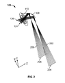
- Figure 2 is a three dimensional perspective view of proximity probe system 100 (shown in Figure 1).
- a first beam of radiation 202 from a first field of view 204 is reflected towards detector 126 by reflector 108.
- the beam arrives at detector 126 off focus such that the energy of beam 202 is substantially uniformly distributed across detector 124 to average the energy received and facilitate improving reliability of the beam information received.
- a second beam of radiation 206 from a second field of view 208 is reflected towards detector 124 by reflector 110.
- the beam arrives at detector 124 off focus such that the energy of beam 206 is substantially uniformly distributed across detector 126 to average the energy received and facilitate improving reliability of the beam information received.
- infrared radiation detection proximity sensors provides a cost-effective and reliable means for monitoring the proximity of an object. More specifically, the use of two sensors in one package facilitates minimizing misalignment of the aperture, reflectors and detectors by accurately locating the two fields of view generated by the system and accurately locating the fields of views with respect to each other. This allows a detection algorithm receiving signals from detectors 124 and 126 to reliably detect a vehicle presence by the difference in signal from the two fields of view. As a result, an infrared radiation based proximity detection system is provided that facilitates detecting approaching other vehicles to the sides of a vehicle to alert the driver to prevent accidents.
- detecting system components illustrated are not limited to the specific embodiments described herein, but rather, components of each detecting system may be utilized independently and separately from other components described herein.
- the detecting system components described above may also be used in combination with other detecting systems.
- Proximity of objects includes the detection of people, vehicles, packages, animals, or any other object.
- proximity probe system 102 base 104 housing 106 sensor 108 first reflector 110 second reflector 112 panel 114 window 116 gasket 118 aperture assembly 120 body 122 aperture 124 detectors 126 detectors 127 electronic circuit 202 first beam of radiation 204 first field of view 206 second beam of radiation 208 second field of view
Landscapes
- Physics & Mathematics (AREA)
- Life Sciences & Earth Sciences (AREA)
- General Life Sciences & Earth Sciences (AREA)
- General Physics & Mathematics (AREA)
- Geophysics (AREA)
- Geophysics And Detection Of Objects (AREA)
Applications Claiming Priority (1)
| Application Number | Priority Date | Filing Date | Title |
|---|---|---|---|
| US11/347,711 US7348538B2 (en) | 2006-02-03 | 2006-02-03 | Methods and systems for detecting proximity of an object |
Publications (1)
| Publication Number | Publication Date |
|---|---|
| EP1816486A1 true EP1816486A1 (fr) | 2007-08-08 |
Family
ID=37989136
Family Applications (1)
| Application Number | Title | Priority Date | Filing Date |
|---|---|---|---|
| EP07101619A Withdrawn EP1816486A1 (fr) | 2006-02-03 | 2007-02-02 | Procédés et systèmes de détection de la proximité d'un objet |
Country Status (3)
| Country | Link |
|---|---|
| US (1) | US7348538B2 (fr) |
| EP (1) | EP1816486A1 (fr) |
| JP (1) | JP2007206078A (fr) |
Families Citing this family (7)
| Publication number | Priority date | Publication date | Assignee | Title |
|---|---|---|---|---|
| DE102006047634A1 (de) * | 2006-10-09 | 2008-04-10 | Robert Bosch Gmbh | Verfahren zum Erfassen eines Umfelds eines Fahrzeugs |
| DE102010003930A1 (de) * | 2010-04-13 | 2011-12-15 | Deltron Elektronische Systeme Gmbh | Anwesenheitssensor und Verfahren zur Erfassung der Anwesenheit einer Person oder eines Tieres |
| US20110317153A1 (en) * | 2010-06-24 | 2011-12-29 | Apple Inc. | Laser peak energy point calibration method and apparatus |
| DE102011056670A1 (de) * | 2010-12-20 | 2012-08-02 | Mattel, Inc. | Näherungssensor-Vorrichtung für ein Spielgerät |
| DE102011052625A1 (de) * | 2011-08-12 | 2013-02-14 | Deltron Elektronische Systeme Gmbh | Anwesenheitssensor und Verfahren zur Erfassung von Personen, Tieren oder Objekten |
| EP3315069A1 (fr) * | 2016-10-25 | 2018-05-02 | Roche Diabetes Care GmbH | Procédé de mesure de la concentration d'analyte dans un fluide corporel et dispositif de mesure de concentration d'analyte |
| US11486968B2 (en) * | 2017-11-15 | 2022-11-01 | Magna Electronics Inc. | Vehicle Lidar sensing system with sensor module |
Citations (6)
| Publication number | Priority date | Publication date | Assignee | Title |
|---|---|---|---|---|
| US4659919A (en) * | 1983-03-28 | 1987-04-21 | Price William E | Optical sensing circuit for audio activation of toys |
| EP0624857A1 (fr) * | 1993-05-11 | 1994-11-17 | Optex Co. Ltd. | Système de détection de type passif d'objet en mouvement |
| WO2000013153A1 (fr) * | 1998-08-27 | 2000-03-09 | Rokonet Electronics Ltd. | Procede et dispositif de detection infrarouge d'effraction |
| US6140648A (en) * | 1997-01-30 | 2000-10-31 | Takenaka Engineering Co., Ltd. | Compound-eye crime prevention sensor system |
| WO2002055335A1 (fr) * | 2001-01-15 | 2002-07-18 | 1138037 Ontario Ltd. ('alirt') | Dispositif et procede de surveillance de l'angle mort |
| WO2004099742A2 (fr) | 2003-05-07 | 2004-11-18 | Peugeot Citroen Automobiles Sa | Dispositif d'exploration optique et vehicule comportant un tel dispositif |
Family Cites Families (19)
| Publication number | Priority date | Publication date | Assignee | Title |
|---|---|---|---|---|
| US3143588A (en) * | 1957-07-11 | 1964-08-04 | Rca Corp | Range measuring system |
| US4251291A (en) * | 1979-02-01 | 1981-02-17 | Gomez Ernesto E | Thermoelectric generator with latent heat storage |
| US6820897B2 (en) * | 1992-05-05 | 2004-11-23 | Automotive Technologies International, Inc. | Vehicle object detection system and method |
| JPS60200133A (ja) * | 1984-03-24 | 1985-10-09 | Matsushita Electric Works Ltd | 赤外線検知装置 |
| EP0322356A3 (fr) * | 1987-12-19 | 1991-06-12 | Baumer Electric Ag | Méthode et dispositif pour la mesure optique de distance |
| JPH0660940B2 (ja) * | 1988-05-25 | 1994-08-10 | ダイキン工業株式会社 | 人体位置検知装置および該装置を備えた空気調和装置 |
| JPH0612505Y2 (ja) * | 1989-03-24 | 1994-03-30 | オプテックス株式会社 | 受動型赤外線検出装置 |
| JP2898843B2 (ja) * | 1993-05-11 | 1999-06-02 | オプテックス株式会社 | 受動型赤外線検知装置 |
| DE4337953A1 (de) * | 1993-11-06 | 1995-05-11 | Abb Patent Gmbh | Vorrichtung zur Erfassung von Lichtstrahlen |
| US5973594A (en) * | 1995-03-29 | 1999-10-26 | Hubbell Incorporated | Multiple optical designs for a multifunction sensor |
| JPH11348695A (ja) * | 1998-06-09 | 1999-12-21 | Nec Corp | 後方車両検知装置 |
| JP3451238B2 (ja) * | 2000-05-09 | 2003-09-29 | マツダマイクロニクス株式会社 | 防犯用サーモパイル放射遠赤外線検出装置 |
| US6470273B2 (en) * | 2000-11-08 | 2002-10-22 | Milton Halsted | Collision warning system |
| DE10059313A1 (de) * | 2000-11-29 | 2002-06-13 | Bosch Gmbh Robert | Anordnung und Verfahren zur Überwachung des Umfelds eines Fahrzeugs |
| JP4990451B2 (ja) * | 2001-08-30 | 2012-08-01 | コンビ株式会社 | 3つ折りタイプのベビーカー |
| US7129519B2 (en) | 2002-05-08 | 2006-10-31 | Advanced Technology Materials, Inc. | Monitoring system comprising infrared thermopile detector |
| JP4251085B2 (ja) * | 2004-01-26 | 2009-04-08 | パナソニック電工株式会社 | 人体検知装置 |
| US7828478B2 (en) * | 2004-09-29 | 2010-11-09 | Delphi Technologies, Inc. | Apparatus and method for thermal detection |
| US7115871B1 (en) * | 2005-08-25 | 2006-10-03 | Inet Consulting Limited Company | Field coverage configurable passive infrared radiation intrusion detection device |
-
2006
- 2006-02-03 US US11/347,711 patent/US7348538B2/en not_active Expired - Fee Related
-
2007
- 2007-02-02 JP JP2007023769A patent/JP2007206078A/ja active Pending
- 2007-02-02 EP EP07101619A patent/EP1816486A1/fr not_active Withdrawn
Patent Citations (6)
| Publication number | Priority date | Publication date | Assignee | Title |
|---|---|---|---|---|
| US4659919A (en) * | 1983-03-28 | 1987-04-21 | Price William E | Optical sensing circuit for audio activation of toys |
| EP0624857A1 (fr) * | 1993-05-11 | 1994-11-17 | Optex Co. Ltd. | Système de détection de type passif d'objet en mouvement |
| US6140648A (en) * | 1997-01-30 | 2000-10-31 | Takenaka Engineering Co., Ltd. | Compound-eye crime prevention sensor system |
| WO2000013153A1 (fr) * | 1998-08-27 | 2000-03-09 | Rokonet Electronics Ltd. | Procede et dispositif de detection infrarouge d'effraction |
| WO2002055335A1 (fr) * | 2001-01-15 | 2002-07-18 | 1138037 Ontario Ltd. ('alirt') | Dispositif et procede de surveillance de l'angle mort |
| WO2004099742A2 (fr) | 2003-05-07 | 2004-11-18 | Peugeot Citroen Automobiles Sa | Dispositif d'exploration optique et vehicule comportant un tel dispositif |
Also Published As
| Publication number | Publication date |
|---|---|
| US7348538B2 (en) | 2008-03-25 |
| JP2007206078A (ja) | 2007-08-16 |
| US20070181784A1 (en) | 2007-08-09 |
Similar Documents
| Publication | Publication Date | Title |
|---|---|---|
| US7501980B2 (en) | Method and device for calibrating sensors in a motor vehicle | |
| EP3396408B1 (fr) | Fusion de données de lidar et de caméra pour véhicule automatisé | |
| EP1816486A1 (fr) | Procédés et systèmes de détection de la proximité d'un objet | |
| US11022691B2 (en) | 3-D lidar sensor | |
| JP7417859B2 (ja) | 距離補正情報の算出方法、測距装置、移動体及びステレオカメラ装置 | |
| CN102749626B (zh) | 雷达传感器、汽车以及目标方位识别方法 | |
| JP2014051284A (ja) | 一体型レーダー−カメラセンサ | |
| JP2001099930A (ja) | 周辺監視センサ | |
| US20120062871A1 (en) | Method and system for the measurement/detection of chemical spillage | |
| EP3629056B1 (fr) | Alignement de capteur de détection d'objets | |
| KR20170114242A (ko) | 확장된 수평 시야각을 가지는 스캐닝 라이다 장치 | |
| KR101903960B1 (ko) | 라이다 장치 | |
| JPH1062551A (ja) | 自動相対位置検出用センサシステム | |
| JP2020177012A (ja) | 光学装置、車載システム、および移動装置 | |
| JP2013108914A (ja) | 物体検知装置 | |
| EP4455718A1 (fr) | Détection de parois et portes en verre et mesure de distance pour robots et son procédé de commande | |
| EP4066016B1 (fr) | Detecteur de brouillard pour un véhicule avec une lentille de forme speciale | |
| KR20200019990A (ko) | 송신기 모듈 및 수신기 모듈을 부착하기 위한 장착 요소를 구비한 라이다 유닛 | |
| US20230366994A1 (en) | Method and device for determining false-positive detections of a lidar sensor | |
| KR101893501B1 (ko) | 통합기상검지기 | |
| KR101887477B1 (ko) | 안전 및 보안 시스템을 위한 가이드 광원을 포함하는 광대역 광센서 시스템 | |
| KR101960417B1 (ko) | 객체인식률을 높인 융합센서 및 이를 구비한 차량 안전지원 시스템 | |
| US20240192341A1 (en) | Method for monitoring an angular position of a lidar system | |
| CN113917491B (zh) | 一种基于ccd激光雷达的一体式大气气溶胶探测系统及方法 | |
| JP4341435B2 (ja) | 距離検出装置 |
Legal Events
| Date | Code | Title | Description |
|---|---|---|---|
| PUAI | Public reference made under article 153(3) epc to a published international application that has entered the european phase |
Free format text: ORIGINAL CODE: 0009012 |
|
| AK | Designated contracting states |
Kind code of ref document: A1 Designated state(s): AT BE BG CH CY CZ DE DK EE ES FI FR GB GR HU IE IS IT LI LT LU LV MC NL PL PT RO SE SI SK TR |
|
| AX | Request for extension of the european patent |
Extension state: AL BA HR MK YU |
|
| 17P | Request for examination filed |
Effective date: 20080208 |
|
| 17Q | First examination report despatched |
Effective date: 20080317 |
|
| AKX | Designation fees paid |
Designated state(s): AT BE BG CH CY CZ DE DK EE ES FI FR GB GR HU IE IS IT LI LT LU LV MC NL PL PT RO SE SI SK TR |
|
| STAA | Information on the status of an ep patent application or granted ep patent |
Free format text: STATUS: THE APPLICATION IS DEEMED TO BE WITHDRAWN |
|
| 18D | Application deemed to be withdrawn |
Effective date: 20140829 |