EP1816637A2 - Bildanzeigevorrichtung und Bildanzeigeverfahren - Google Patents
Bildanzeigevorrichtung und Bildanzeigeverfahren Download PDFInfo
- Publication number
- EP1816637A2 EP1816637A2 EP07250408A EP07250408A EP1816637A2 EP 1816637 A2 EP1816637 A2 EP 1816637A2 EP 07250408 A EP07250408 A EP 07250408A EP 07250408 A EP07250408 A EP 07250408A EP 1816637 A2 EP1816637 A2 EP 1816637A2
- Authority
- EP
- European Patent Office
- Prior art keywords
- period
- ratio
- value
- black
- image
- Prior art date
- Legal status (The legal status is an assumption and is not a legal conclusion. Google has not performed a legal analysis and makes no representation as to the accuracy of the status listed.)
- Withdrawn
Links
Images





Classifications
-
- G—PHYSICS
- G09—EDUCATION; CRYPTOGRAPHY; DISPLAY; ADVERTISING; SEALS
- G09G—ARRANGEMENTS OR CIRCUITS FOR CONTROL OF INDICATING DEVICES USING STATIC MEANS TO PRESENT VARIABLE INFORMATION
- G09G3/00—Control arrangements or circuits, of interest only in connection with visual indicators other than cathode-ray tubes
- G09G3/20—Control arrangements or circuits, of interest only in connection with visual indicators other than cathode-ray tubes for presentation of an assembly of a number of characters, e.g. a page, by composing the assembly by combination of individual elements arranged in a matrix no fixed position being assigned to or needed to be assigned to the individual characters or partial characters
- G09G3/34—Control arrangements or circuits, of interest only in connection with visual indicators other than cathode-ray tubes for presentation of an assembly of a number of characters, e.g. a page, by composing the assembly by combination of individual elements arranged in a matrix no fixed position being assigned to or needed to be assigned to the individual characters or partial characters by control of light from an independent source
- G09G3/36—Control arrangements or circuits, of interest only in connection with visual indicators other than cathode-ray tubes for presentation of an assembly of a number of characters, e.g. a page, by composing the assembly by combination of individual elements arranged in a matrix no fixed position being assigned to or needed to be assigned to the individual characters or partial characters by control of light from an independent source using liquid crystals
-
- G—PHYSICS
- G09—EDUCATION; CRYPTOGRAPHY; DISPLAY; ADVERTISING; SEALS
- G09G—ARRANGEMENTS OR CIRCUITS FOR CONTROL OF INDICATING DEVICES USING STATIC MEANS TO PRESENT VARIABLE INFORMATION
- G09G3/00—Control arrangements or circuits, of interest only in connection with visual indicators other than cathode-ray tubes
- G09G3/20—Control arrangements or circuits, of interest only in connection with visual indicators other than cathode-ray tubes for presentation of an assembly of a number of characters, e.g. a page, by composing the assembly by combination of individual elements arranged in a matrix no fixed position being assigned to or needed to be assigned to the individual characters or partial characters
- G09G3/34—Control arrangements or circuits, of interest only in connection with visual indicators other than cathode-ray tubes for presentation of an assembly of a number of characters, e.g. a page, by composing the assembly by combination of individual elements arranged in a matrix no fixed position being assigned to or needed to be assigned to the individual characters or partial characters by control of light from an independent source
- G09G3/3406—Control of illumination source
- G09G3/342—Control of illumination source using several illumination sources separately controlled corresponding to different display panel areas, e.g. along one dimension such as lines
-
- G—PHYSICS
- G09—EDUCATION; CRYPTOGRAPHY; DISPLAY; ADVERTISING; SEALS
- G09G—ARRANGEMENTS OR CIRCUITS FOR CONTROL OF INDICATING DEVICES USING STATIC MEANS TO PRESENT VARIABLE INFORMATION
- G09G3/00—Control arrangements or circuits, of interest only in connection with visual indicators other than cathode-ray tubes
- G09G3/20—Control arrangements or circuits, of interest only in connection with visual indicators other than cathode-ray tubes for presentation of an assembly of a number of characters, e.g. a page, by composing the assembly by combination of individual elements arranged in a matrix no fixed position being assigned to or needed to be assigned to the individual characters or partial characters
-
- G—PHYSICS
- G09—EDUCATION; CRYPTOGRAPHY; DISPLAY; ADVERTISING; SEALS
- G09G—ARRANGEMENTS OR CIRCUITS FOR CONTROL OF INDICATING DEVICES USING STATIC MEANS TO PRESENT VARIABLE INFORMATION
- G09G5/00—Control arrangements or circuits for visual indicators common to cathode-ray tube indicators and other visual indicators
-
- G—PHYSICS
- G09—EDUCATION; CRYPTOGRAPHY; DISPLAY; ADVERTISING; SEALS
- G09G—ARRANGEMENTS OR CIRCUITS FOR CONTROL OF INDICATING DEVICES USING STATIC MEANS TO PRESENT VARIABLE INFORMATION
- G09G2310/00—Command of the display device
- G09G2310/02—Addressing, scanning or driving the display screen or processing steps related thereto
- G09G2310/024—Scrolling of light from the illumination source over the display in combination with the scanning of the display screen
-
- G—PHYSICS
- G09—EDUCATION; CRYPTOGRAPHY; DISPLAY; ADVERTISING; SEALS
- G09G—ARRANGEMENTS OR CIRCUITS FOR CONTROL OF INDICATING DEVICES USING STATIC MEANS TO PRESENT VARIABLE INFORMATION
- G09G2310/00—Command of the display device
- G09G2310/06—Details of flat display driving waveforms
- G09G2310/061—Details of flat display driving waveforms for resetting or blanking
-
- G—PHYSICS
- G09—EDUCATION; CRYPTOGRAPHY; DISPLAY; ADVERTISING; SEALS
- G09G—ARRANGEMENTS OR CIRCUITS FOR CONTROL OF INDICATING DEVICES USING STATIC MEANS TO PRESENT VARIABLE INFORMATION
- G09G2320/00—Control of display operating conditions
- G09G2320/02—Improving the quality of display appearance
- G09G2320/0247—Flicker reduction other than flicker reduction circuits used for single beam cathode-ray tubes
-
- G—PHYSICS
- G09—EDUCATION; CRYPTOGRAPHY; DISPLAY; ADVERTISING; SEALS
- G09G—ARRANGEMENTS OR CIRCUITS FOR CONTROL OF INDICATING DEVICES USING STATIC MEANS TO PRESENT VARIABLE INFORMATION
- G09G2320/00—Control of display operating conditions
- G09G2320/02—Improving the quality of display appearance
- G09G2320/0261—Improving the quality of display appearance in the context of movement of objects on the screen or movement of the observer relative to the screen
-
- G—PHYSICS
- G09—EDUCATION; CRYPTOGRAPHY; DISPLAY; ADVERTISING; SEALS
- G09G—ARRANGEMENTS OR CIRCUITS FOR CONTROL OF INDICATING DEVICES USING STATIC MEANS TO PRESENT VARIABLE INFORMATION
- G09G2320/00—Control of display operating conditions
- G09G2320/06—Adjustment of display parameters
- G09G2320/0626—Adjustment of display parameters for control of overall brightness
- G09G2320/0633—Adjustment of display parameters for control of overall brightness by amplitude modulation of the brightness of the illumination source
-
- G—PHYSICS
- G09—EDUCATION; CRYPTOGRAPHY; DISPLAY; ADVERTISING; SEALS
- G09G—ARRANGEMENTS OR CIRCUITS FOR CONTROL OF INDICATING DEVICES USING STATIC MEANS TO PRESENT VARIABLE INFORMATION
- G09G2320/00—Control of display operating conditions
- G09G2320/06—Adjustment of display parameters
- G09G2320/0626—Adjustment of display parameters for control of overall brightness
- G09G2320/0646—Modulation of illumination source brightness and image signal correlated to each other
-
- G—PHYSICS
- G09—EDUCATION; CRYPTOGRAPHY; DISPLAY; ADVERTISING; SEALS
- G09G—ARRANGEMENTS OR CIRCUITS FOR CONTROL OF INDICATING DEVICES USING STATIC MEANS TO PRESENT VARIABLE INFORMATION
- G09G2320/00—Control of display operating conditions
- G09G2320/10—Special adaptations of display systems for operation with variable images
- G09G2320/103—Detection of image changes, e.g. determination of an index representative of the image change
-
- G—PHYSICS
- G09—EDUCATION; CRYPTOGRAPHY; DISPLAY; ADVERTISING; SEALS
- G09G—ARRANGEMENTS OR CIRCUITS FOR CONTROL OF INDICATING DEVICES USING STATIC MEANS TO PRESENT VARIABLE INFORMATION
- G09G2340/00—Aspects of display data processing
- G09G2340/16—Determination of a pixel data signal depending on the signal applied in the previous frame
-
- G—PHYSICS
- G09—EDUCATION; CRYPTOGRAPHY; DISPLAY; ADVERTISING; SEALS
- G09G—ARRANGEMENTS OR CIRCUITS FOR CONTROL OF INDICATING DEVICES USING STATIC MEANS TO PRESENT VARIABLE INFORMATION
- G09G2360/00—Aspects of the architecture of display systems
- G09G2360/18—Use of a frame buffer in a display terminal, inclusive of the display panel
-
- G—PHYSICS
- G09—EDUCATION; CRYPTOGRAPHY; DISPLAY; ADVERTISING; SEALS
- G09G—ARRANGEMENTS OR CIRCUITS FOR CONTROL OF INDICATING DEVICES USING STATIC MEANS TO PRESENT VARIABLE INFORMATION
- G09G3/00—Control arrangements or circuits, of interest only in connection with visual indicators other than cathode-ray tubes
- G09G3/20—Control arrangements or circuits, of interest only in connection with visual indicators other than cathode-ray tubes for presentation of an assembly of a number of characters, e.g. a page, by composing the assembly by combination of individual elements arranged in a matrix no fixed position being assigned to or needed to be assigned to the individual characters or partial characters
- G09G3/34—Control arrangements or circuits, of interest only in connection with visual indicators other than cathode-ray tubes for presentation of an assembly of a number of characters, e.g. a page, by composing the assembly by combination of individual elements arranged in a matrix no fixed position being assigned to or needed to be assigned to the individual characters or partial characters by control of light from an independent source
- G09G3/36—Control arrangements or circuits, of interest only in connection with visual indicators other than cathode-ray tubes for presentation of an assembly of a number of characters, e.g. a page, by composing the assembly by combination of individual elements arranged in a matrix no fixed position being assigned to or needed to be assigned to the individual characters or partial characters by control of light from an independent source using liquid crystals
- G09G3/3611—Control of matrices with row and column drivers
- G09G3/3648—Control of matrices with row and column drivers using an active matrix
Definitions
- the present invention relates to an image display device in which the quality of a moving image and a still image is improved while restraining increase in power consumption.
- CTR cathode ray tube
- the liquid crystal display device and the organic EL display have a problem such that the image appears to be blurred when the moving image is displayed. This problem is caused by the fact that temporal characteristics of an image display method are different between the liquid crystal display device or the organic EL display and the CRT. The cause of this problem will be described in detail below.
- the liquid crystal display device or the organic EL display in which a transistor is used as a selection switch for display/non-display for each pixel is a display device in which a display method in which a displayed image is held for one frame period (hereinafter, referred to as a hold-type display) is employed.
- the CRT is a display device in which a display method in which each pixel becomes dark after having illuminated for a certain period (hereinafter, referred to as an impulse-type display) is employed.
- the same image is kept displayed from the timing when a certain frame of the moving image is displayed until the timing when the next frame thereof is displayed. From the timing when a frame N in the moving image is displayed until the timing when the next frame N+1 is displayed (between frames), the image of the frame N is kept displayed.
- the moving object stands still on a screen from the timing when the frame N is displayed until the frame N+1 is displayed.
- the moving object moves discontinuously.
- a second method of determining whether an input image is a moving image or a still image and displaying black between continuous frames only when it is the moving image is also proposed in the related art (for example, see JP-A-2002-123223 ).
- a pseudo-impulse-type display is carried out such as the CRT by intentionally turning the liquid crystal screen black between frames to restrain deterioration of the moving image quality.
- the power consumption of a backlight which is illuminated during the black display as well is wasteful.
- flicker caused by the impulse-type display occurs.
- an image display device including:
- the quality of the moving image and the still image displayed on the image display device can be improved as much as possible while restraining increase in power consumption and the flicker.
- a liquid crystal display device 10 according to a first embodiment of the invention will be described.
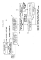
- Fig. 1 shows a configuration of the liquid crystal display device 10.
- An input video signal is supplied to a frame memory 12, a moving image/still image determination unit 14, and a target black display period ratio calculating unit 16.
- the frame memory 12 holds the input video signal for one frame period, and outputs the same to the moving image/still image determination unit 14 as a video signal delayed by one frame.
- the term "one frame” corresponds to a piece of image displayed on the liquid crystal display device 10, and the term “one field” which is generally referred regarding an interlace video signal and the term “one frame” here are identical.
- the moving image/still image determination unit 14 detects a magnitude of the movement between temporally adjacent two frames using the input video signal and the video signal delayed by one frame period by the frame memory 12, and outputs the result to the target black display period ratio calculating unit 16 as movement information.
- the target black display period ratio calculating unit 16 calculates the ratio of black display period in one frame period of black display which is displayed between frames of the input video signal displayed on the liquid crystal panel 26 on the basis of the input movement information, and outputs the result to a black display period ratio change amount calculating unit 18 as information on discrete target ratios of black display period.
- the black display period ratio change amount calculating unit 18 calculates the amount of change in ratio of black display period per one frame on the basis of the ratio of black display period in the past frame and the supplied discrete target ratios of black display period, and outputs the same to a black display period ratio determining unit 20.
- the black display period ratio determining unit 20 adds the supplied amount of change in ratio of black display period to the ratio of black display period in the previous frame to determine the ratio of black display period for performing actual display, and outputs the same to a black display period control unit 22 and a backlight luminance control unit 24.
- the black display period control unit 22 outputs the video signal to be displayed on the liquid crystal panel 26 and a control signal for driving the liquid crystal panel 26 (horizontal synchronous signal, vertical synchronous signal, and so on) to the liquid crystal panel 26 on the basis of the supplied ratio of black display period.
- the backlight luminance control unit 24 determines the luminance of a backlight 28 on the basis of the supplied ratio of black display period and outputs the same to the backlight 28 as a backlight luminance control signal.
- the liquid crystal panel 26 displays a video signal in which black displays are inserted between the frames on the basis of the input video signal and the control signal.
- the backlight 28 is emitted at a luminance on the basis of the backlight luminance control signal.
- the moving image/still image determination unit 14, the target black display period ratio calculating unit 16, the black display period ratio change amount calculating unit 18, the black display period ratio determining unit 20, the black display period control unit 22 and the backlight luminance control unit 24 in this embodiment are realized by a timing controller IC of the liquid crystal display device. However, they may be realized by causing a computer to implement programs having these functions.
- the moving image/still image determination unit 14 detects the moving image/still image using a plurality of frames in the input video signal and outputs the same as movement information.
- the input video signal is held for one frame period in the frame memory 12, and the moving image/still image is detected using the video signal delayed by one frame and the input video signal, that is, the temporally adjacent two frames.
- the frames for detecting the moving image/still image are not limited to the two temporally adjacent two frames, and, for example, in a case in which the input video signal is an interlaced video signal, detection of the moving image/still image can be performed using only even fields or odd fields.
- moving image/still image detecting means may be of various types, in this embodiment, the sum of absolute differences (SAD) between the two frames is employed as the movement information.
- SAD represents the sum of absolute differences and f (u, v, n) represents the value Y of the pixel at a position (u, v) of the n th frame.
- F(u, v, n) is expressed as in Expression 2 as a linear sum of the pixel values (tones) of red, green and blue.
- R(u, v, n), G(u, v, n) andB(u, v, n) represent the pixel values of red, green and blue in the positions (u, v) respectively.
- the sum of absolute differences of the value Y is obtained.
- a configuration to obtain the sum of absolute differences of the pixel values of red, green and blue is also applicable.
- the sum of absolute differences is obtained for all the pixels in one frame.
- a configuration in which the sum of absolute differences is obtained for discrete pixels is also applicable.
- a configuration in which one frame is sub sampled, and the sum of absolute differences is obtained for a sub sampled image is also applicable.
- a configuration in which the sum of absolute differences between frames may be obtained every two frame, or other several frames other than between the adjacent frames is also applicable.
- a method of determining the movement information of the current frame using the movement information of several frames in the past may be employed. For example, a median value processing is performed from the movement information of the past five frames, and the movement information of the median values is employed as the movement information of the current frame.
- the target black display period ratio calculating unit 16 calculates the discrete target ratios of black display period on the basis of the input movement information.
- the target ratio of black display period is obtained as the continuous values from a movement information value (that is, the target value).
- B D (N) represents the discrete target ratio of black display period of the N th frame
- B T (N) represents the target ratio of black display period of the N th frame
- Th represents a threshold value used for the discretization.
- the relation between the target ratio of black display period and the value of the movement information may be set in advance such that the target ratio of black display period becomes a large value when the movement information value is large.
- the target ratio of black display period is preferably processed so as to fall between a minimum value in the discrete target ratio of black display period and a maximum value in the discrete target ratio of black display period.
- the discrete target ratios of black display period are set to 0% as the minimum value and 50% as the maximum value.
- the threshold value is a fixed value
- the discrete target ratios of black display period may be 0% or 50% from frame to frame if the value of the target ratio of black display period is a value near the threshold value. Therefore, the threshold value is varied according to the discrete target ratios of black display period of the previous frame and the target ratio of black display period of the current frame as shown in Expression 4.
- Expression 4 Th ⁇ Th B D ⁇ N - 1 ⁇ B T N Th + C otherwise
- C represents a value which determines redundancy for the threshold value.
- the operation will be described in a case in which the threshold value is assumed to be 0.25, the C is assumed to be -0.1, and the current target ratio of black display period is 0.2.
- the threshold value is 0.25 and, consequently, the discrete target ratio of black display period of the current frame is set to 0.
- a variable threshold value as shown in Expression 4
- the threshold value when the discrete target ratio of black display period of the previous frame is 0.5 becomes a small value, and hence the discrete target ratio of black display period of the current frame can easily be set to 0.5. In other words, the ratio of black display period is stabilized to the target ratio of black display period which realizes a moving image in good quality.
- the discrete target ratios of black display period are set to two values of 0% and 50%.
- the discrete target ratios of black display period may be set to three or more values in the same manner.
- the discrete target ratios of black display period between which the current target ratio of black display period exists are inspected.
- the discrete target ratios of black display period are set to 0, 0.25 and 0.5, it can be obtained using Expression 5.
- B D . H ⁇ 0.25 B T N ⁇ 0.25 0.5 otherwise
- B D . L ⁇ 0 B T N ⁇ 0.25 0.25 otherwise
- B D, H is the maximum value of the discrete target ratio of black display period in which the target ratio of black display period is included
- B D, L is the minimum value of the discrete target ratio of black display period in which the target ratio of black display period is included.
- the range of the discrete target ratio of black display period including the target ratio of black display period is determined by Expression 5, and then the threshold value is set by Expression 4 (the value of Th is set in advance for each range of discrete target ratio of black display period in which the target ratio of black display period is included), and finally, the discrete target ratio of black display period is calculated by Expression 6.
- B D N ⁇ B D . L B T N ⁇ Th B D . H otherwise
- the discrete target ratio of black display period obtained by the procedure described above is supplied to the black display period ratio change amount calculating unit 18, and the amount of change in ratio of black display period in one frame period is calculated.
- the amount of change in ratio of black display period is set to restrain flicker occurring due to an abrupt change in the current ratio of black display period (that is, the output value) as much as possible.
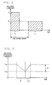
- the relative display luminance during the period t0 is assumed to be L0
- the relative display luminance during the period t1 is assumed to be L1. Since the average luminance of one frame period is constant irrespective of the ratio of image display period, Expression 7 is satisfied.
- a relative integrated luminance during one frame period in a case in which the ratio of image display period is changed from to to t1 is considered.
- the humane eye perceives the brightness by integrating stimulation that the retina has received during a certain period. Therefore, the brightness which is perceived by integrating the luminance of the liquid crystal display device 10 during one frame period is modeled.
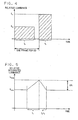
- Fig. 3 shows a temporal change in the relative integrated luminance during one frame period in a case in which the ratio of image display period is changed from t0 to t1.
- the horizontal axis represents time and the vertical axis represents the relative integrated luminance.
- ⁇ represents the constant of proportionality
- the flicker perceived when the ratio of image display period is changed from t0 to t1 is proportional to the amount of change in ratio of image display period, that is, the amount of change in ratio of black display period from Expression 11 and Expression 15. Therefore, by setting a transient black display period by the amount of change in ratio of black display period in which the perceived flicker is lower than recognizable limit, occurrence of the flicker due to the abrupt change in ratio of black display period can be restrained.
- the amount of change in black display period is set and the amount of change in ratio of black display period from frame to frame is set to 3%.
- the calculated ratio of black display period is supplied to the black display period control unit 22 and the backlight luminance control unit 24.
- the black display period control unit 22 outputs the video signal and the control signal (horizontal, vertical synchronous signal, and so on) for driving the liquid crystal panel 26 in accordance with the calculated ratio of black display period.
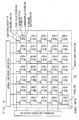
- the liquid crystal panel 26 is of an active matrix type, and as shown in Fig. 6, a plurality of signal lines 52 and a plurality of scanning lines 54 are arranged on an array substrate 50 via an insulating layer, not shown, in a matrix pattern, and pixels 58 are formed at respective intersecting points of the both lines. Ends of the signal lines 52 and the scanning lines 54 intersecting thereto are connected to a signal line drive circuit 60 and a scanning line drive circuit 62, respectively.
- a switch element 72 composed of a thin film transistor (TFT) is the switch element 72 for writing a video signal, and gates of thereof in the respective horizontal line are connected to the common scanning line 54, and sources thereof in the respective vertical lines are connected to the common signal line 52.
- a drain is connected to a pixel electrode 64, and is connected to a storage capacitor 66 arranged in electrically parallel with the pixel electrode 64.
- the pixel electrodes 64 are formed on the array substrate 50, and common electrodes 68 electrically opposite from the pixel electrodes 64 are formed on a common substrate, not shown.
- the common electrodes 68 are provided with predetermined common voltage from a common voltage generating circuit, not shown.
- a liquid crystal layer 70 is held between the pixel electrodes 64 and the common electrodes 68, and the peripheries of the array substrate 50 and the common substrate are sealed by a sealing material, not shown.
- the liquid crystal material used for the liquid crystal layer 70 may be of any type, but preferably, the one which can respond relatively quickly since two image signals for image display and black display are required to be written during one frame period in the case of the liquid crystal panel 26 in this embodiment as described later.
- ferroelectric liquid crystal and liquid crystal of OCB (Optically compensated Bend) mode are recommended.
- the scanning line drive circuit 62 includes a shift register, a level shifter and a buffer circuit, not shown.
- the scanning line drive circuit 62 outputs a line selecting signal for the respective scanning lines 54 on the basis of a vertical start signal or a vertical clock signal outputted from a ratio of display control unit as a control signal.
- the signal line drive circuit 60 includes an analogue switch, a shift register, a sample hold circuit, and a video bus, not shown.
- a horizontal start signal and a horizontal clock signal outputted from the ratio of display control unit as a control signal as well as a video signal are supplied to the signal line drive circuit 60.
- Fig. 7 is a timing chart of the liquid crystal panel 26.
- Fig. 7 shows display signals outputted from the signal line drive circuit 60 and drive waveforms of the scanning line signals outputted from the scanning line drive circuit 62, and the states of image display on the liquid crystal panel 26.
- blanking periods are not shown in Fig. 7 for simplicity of the drawing, the drive signal of the general liquid crystal panel 26 has horizontal and vertical blanking periods.
- An image display signal is outputted in a first half of one horizontal scanning period, and a black display signal is outputted in a second half thereof from the signal line drive circuit 60.
- scanning line drive circuit 62 scanning lines corresponding to the respective pixels 58 to which the image display signals should be supplied are selected in the first half of one horizontal scanning period, and scanning lines corresponding to the respective pixels 58 to which the black display signals should be supplied are selected in the second half of one horizontal scanning period.
- Fig. 7 is a timing chart in the case in which the ratio of black display period is 50%. Representing the number of vertical scanning lines by V, when selecting the first scanning line in the first half of the one horizontal scanning period and supplying the image display signal to the corresponding pixel 58, the V/2+1 st scanning line is selected in the second half of the one horizontal scanning period to supply the black display signal to the corresponding pixel 58. In the same manner, When the second scanning line is selected in the first half of the one horizontal scanning period, the V/2+2 nd scanning line is selected in the second half of the one horizontal scanning line. In the same manner, the next scanning line is selected in the first half and the second half of the one horizontal scanning period in sequence.
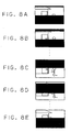
- Fig. 8 shows a displayed state on the liquid crystal panel 26 in the case in which the ratio of black display period is 50%.
- Fig. 8A shows a displayed state when writing of the image display signal of n th frame is completed until the V/2+1 st line and the black display signal is written into the first line.
- Fig. 8B shows a displayed state when writing of the image display signal of the n th frame is completed until the V/2+2 nd line and the black display signal is written into the second line.
- Fig. 8C shows a displayed state when writing of the image display signal of the n th frame is written into the V th line and the black display signal is written into the V/2-1 st line.
- Fig. 8D shows a displayed state when the image display signal of the n+1 st frame is written into the first line, and the black display signal is written into the V/2 nd line.
- Fig. 8E shows a displayed state when the image display signal of the n+1 st frame is written into the V/2 nd line and the black display signal is written into the V th line.
- desired black display period can be set by changing the timing to start writing the black display signal in the same manner, that is, by changing the timing of the scanning line signal. Therefore, the image can be displayed on the liquid crystal panel 26 at the desired ratio of black display period by outputting the control signal at the timing to start writing of the black display signal corresponding to the ratio of black display period from the black display period control unit 22 and inputting the same to the liquid crystal panel 26.
- the backlight luminance control unit 24 outputs a backlight luminance control signal for controlling a light source of the backlight 28 using supplied information on ratio of black display period.
- the light source of the backlight 28 is an analogue-modulated LED
- a pulse width modulating signal if the light source is a pulse width modulated (PWM) LED.
- the light source is a cold-cathode tube, it outputs an analogue voltage to be supplied to an inverter for illuminating the cold-cathode tube.
- an LED light source of a pulse width modulating system in which a large dynamic range of luminance can be ensured in a relatively simple configuration is employed.
- the relation between the pulse width to be supplied to the LED light source and the luminance of the backlight 28 is measured in advance, and stored in the backlight luminance control unit 24.
- data to be stored may be, for example, a function when the relation described above can be represented by the function, or may be stored as LUT (Look-up Table) in a ROM.
- the LED light source has a configuration to display white by mixing the LEDs of three primary colors of red, green and blue, data for the respective LEDs is preferably stored.
- the above described operation is performed at various ratios of black display period to obtain the relation between the ratio of black display period and the pulse width, and the results are stored as data.
- the luminance of the backlight 28 is controlled, and the luminance on the liquid crystal panel 26 can be maintained substantially at a constant value with respect to the arbitrary ratio of black display period.
- a method of installing a photodiode in the backlight 28, feeding back the luminance of the backlight 28 while measuring with the photodiode, and controlling the luminance of the LED light source is also applicable.
- the LED light source varies in light-emitting characteristics depending on the temperature, the configuration of feeding back the measured values of luminance using the photodiode as described above is effective.
- Fig. 9 shows a relation among the ratio of black display period , the relative transmissivity of the liquid crystal panel, the relative luminance of the backlight, and the relative luminance of the liquid crystal display device when the range of the ratio of black display period is set to 0% to 50%.
- the horizontal axis represents the ratio of black display period
- the left vertical axis represents the relative transmissivity with respect to the transmissivity of the liquid crystal panel 26 when the ratio of black display period is 0%
- the right vertical axis represents the relative luminance with respect to the luminance of the backlight 28 when the ratio of black display period is 50%.
- the transmissivity is decreased linearly with increase in ratio of black display period. Therefore, the luminance of the backlight 28 is controlled in such a manner that the luminance of the backlight 28 increases with increase in ratio of black display period and the relative luminance of the liquid crystal display device 10, that is, the luminance after having passed through the liquid crystal panel 26 is kept at a constant value.
- the relation between the ratio of black display period and the relative luminance of the backlight 28 is obtained and, the relation between the ratio of black display period and the pulse width can be obtained from the relation between the relative illumination of the backlight and the pulse width to be supplied to the LED light source, and then, the luminance control signal for the backlight 28 represented by the pulse width can be obtained from the information on ratio of black display period obtained by the black display period ratio control unit 22.
- the backlight 28 can be configured with various types of light sources described above, in this embodiment, a subjacent type backlight 28 having the LED as the light source is employed.
- the configuration of the backlight 28 is not limited to the one shown above and, for example, the edge light type backlight 28 having a light guide plate may also be employed.
- the backlight 28 is controlled in its luminance by the luminance control signal for the backlight 28 outputted from the backlight luminance control unit 24.
- the quality of displayed input video image can be improved while restraining increase in power consumption by changing the ratio of black display period depending on whether the input video image is a moving image or a still image.
- the ratio of black display period can be stabilized for various video images.
- liquid crystal display device 10 according to the second embodiment will be described.
- the basic configuration of the liquid crystal display device 10 in this embodiment is the same as the one in the first embodiment. However, the operation of the target black display period ratio calculating unit 16 and the black display period ratio change amount calculating unit 18 is different from that of the first embodiment.
- the target black display period ratio calculating unit 16 calculates the discrete target ratios of black display period by Expression 3 as in the first embodiment. However, the redundancy is not provided to the threshold value as in the first embodiment, and is a fixed value. In this embodiment, the discrete target ratios of black display period are calculated by applying the threshold processing to the target ratio of black display period. However, the above-described discretization is not essential, and the target ratio of black display period obtained from the movement information can be supplied as is to the black display period ratio change amount calculating unit 18.
- the black display period ratio change amount calculating unit 18 calculates the amount of change in ratio of black display period for one frame according to the difference between the ratio of black display period of the previous frame and the supplied discrete target ratio of black display period using Expression 18.
- Expression 18 ⁇ ⁇ B ⁇ ⁇ ⁇ B 1 B ⁇ N - 1 > B D N ⁇ ⁇ B 2 otherwise
- ⁇ B 1 and ⁇ B 2 represent the amounts of change in ratio of black display period for one frame in the cases where the discrete target ratio of black display period is smaller and larger than the ratio of black display period of the previous frame respectively.
- the values of ⁇ B 1 and ⁇ B 2 may be various values. However, as described in the first embodiment as well, they are preferably set to a value not to exceed the amount of change at which flicker in association with the change in black display period is not viewed, and more preferably, they are set to satisfy the relation ⁇ B 1 ⁇ B 2 . This is because the ratio of black display period can be stabilized to a large value, that is, to a state in which the good quality of moving image is ensured by setting the amount of change to be ⁇ B 1 ⁇ B 2 as in the first embodiment.
- Expression 18 calculates the amount of change in ratio of black display period with the discrete target ratio of black display period as an input. However, a configuration to input the non-discretized target ratio of black display period can also be employed. In this case, Expression 18 is expressed as Expression 19. Expression 19 ⁇ ⁇ B ⁇ ⁇ ⁇ B 1 B ⁇ N - 1 > B T N ⁇ ⁇ B 2 otherwise
- the quality of the displayed input video image can be improved while restraining increase in power consumption by changing the ratio of black display period depending on whether the input video image is a moving image or a still image.
- the ratio of black display period can be stabilized for various video images.
- liquid crystal display device 10 according to the third embodiment will be described.
- the basic configuration of the liquid crystal display device 10 in this embodiment is the same as the one in the first embodiment. However, the operation of the target black display period ratio calculating unit 16 and the black display period ratio change amount calculating unit 18 is different from that of the first embodiment.
- the target black display period ratio calculating unit 16 calculates the discrete target ratios of black display period by Expression 3 as in the first embodiment. However, the redundancy is not provided to the threshold value as in the first embodiment, and is a fixed value. In this embodiment, the discrete target ratios of black display period are calculated by applying the threshold processing to the target ratio of black display period. However, the above-described discretization is not essential, and the target ratio of black display period obtained from the movement information can be supplied as is to the black display period ratio change amount calculating unit 18.
- the black display period ratio change amount calculating unit 18 calculates the amount of change in ratio of black display period on the basis of the difference values obtained by subtracting the ratios of black display period in the plurality of frames in the past from the discrete target ratios of black display period in the plurality of frames in the past respectively. More specifically, as shown in Expression 20, the amount of change in ratio of black display period is set to a predetermined value when all the difference values obtained by subtracting the ratios of black display period in the plurality of frames in the past time from the discrete target ratios of black display period in the plurality of frames in the past respectively are positive values or negative values, and is set to 0 in other cases.
- the amount of change in ratio of black display period is calculated on the basis of the differences between the discrete target ratios of black display period and the ratios of black display period in n frames in the past.
- the different amount of change in ratio of black display period is employed depending on whether the differential values are positive values or negative values including the configuration according to the second embodiment.
- ⁇ B 1 and ⁇ B 2 may be the same value.
- the amount of change in ratio of black display period is set to 0. Therefore, a stable ratio of black display period can be obtained.
- Expression 20 the discrete target ratios of black display period are supplied as input.
- a configuration in which the target ratio of black display period is supplied as input as in Expression 21 is also applicable.
- the quality of the displayed input video image can be improved while restraining increase in power consumption by changing the ratio of black display period depending on whether the input video image is a moving image or a still image.
- the ratio of black display period can be stabilized for various video images.
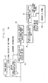
- Fig. 10 shows a configuration of the liquid crystal display device 10 according to this embodiment.
- the basic configuration of the liquid crystal display device 10 in this embodiment is the same as the one in the first embodiment, and is characterized in that the ratio of black display period of an input video image displayed on the liquid crystal display device 10 is controlled by controlling lighting and extinction of the backlight 28.
- the ratio of black display period is determined from the input video image by the same configuration as in the first embodiment.
- the determined ratio of black display period is supplied to the backlight luminance control unit 24 as information on ratio of black display period.
- the backlight luminance control unit 24 determines the light-emitting period of the backlight 28 and the light-emitting luminance of the backlight 28 on the basis of the information on ratio of black display period, and supplies the same to the backlight 28 as a ratio of light emission control signal for the backlight 28 and a luminance control signal for the backlight 28.
- the backlight 28 emits light on the basis of the supplied ratio of light emission control signal for the backlight 28 and the luminance control signal for the backlight 28.
- Fig. 11 the operation of the liquid crystal panel 26 and the backlight 28 is shown.
- the horizontal axis represents time and the vertical axis represents a vertical display position of the liquid crystal panel 26.
- a video image is written into line sequence from the top of the screen as one faces. Therefore, writing to the liquid crystal panel 26 is performed in such a manner that the video image is written into the liquid crystal panel 26 while shifting the writing time little by little from the top of the screen as one faces as shown in Fig. 11.
- writing into the liquid crystal panel 26 is performed while spending one frame period (generally, 1/60 second). However, in this embodiment, it is written into a period shorter than one frame period, that is, 1/4 frame period (1/240 second).
- the backlight 28 When a predetermined period from a timing when the video image is written into a lower most line of the liquid crystal panel 26 until the completion of response of the liquid crystal has elapsed, the backlight 28 emits light according to the light emission ratio control signal for the backlight 28.
- the light-emitting luminance of the backlight 28 is determined by the light-emitting period of the backlight 28, and control is made to make the product of the light-emitting period and the light-emitting luminance of the backlight 28 become substantially constant.
- the backlight 28 is preferably extinguished during the period of writing in the liquid crystal panel 26 and the response period of the liquid crystal. It is because part of a video image in the previous frame is displayed on the liquid crystal panel 26 during the period of writing in the liquid crystal panel 26 and the response period of the liquid crystal, and hence if the backlight 28 emits light during this period, the previous frame and the current frame are perceived to an observer in mixture.
- the ratio of black display period of the liquid crystal display device 10 can be controlled as in the first embodiment.
- the quality of the displayed input video image can be improved while restraining increase in power consumption by changing the ratio of black display period depending on whether the input video image is a moving image or a still image.
- the ratio of black display period can be stabilized for various video images.
- Fig. 12 shows a configuration of the liquid crystal display device 10 in this embodiment.
- the basic configuration of the liquid crystal display device 10 in the fifth embodiment is the same as the one in the fourth embodiment. However, the light-emitting area of the backlight 28 is divided so that the backlight 28 can be emitted at different timings.
- FIG. 13 An example of the structure of the backlight 28 is shown in Fig. 13.
- Fig. 13 is a structure referred to as a subjacent type backlight 28, which includes cold cathode tubes 80 aligned as light sources and the respective cold cathodes tubes 80 surrounded by a reflector plate 82.
- a diffuser panel 84 is installed above the cold cathode tubes 80 to diffuse light from the cold cathode tubes 80 so that a uniform surface light source is achieved.
- the timings of light emission of the respective cold cathode tubes 80 are differentiated.
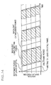
- Fig. 14 shows the operation of the liquid crystal panel 26 and the backlight 28.
- the backlight 28 is divided into four parts in the horizontal direction, and the respective areas can control the timings of light emission and extinction of the backlight 28.
- the timing of light emission of the backlight 28 is when a predetermined period has elapsed after the writing into the lower most line of the liquid crystal panel 26 is completed.
- the respective parts of the backlight 28 emit light when the response period of the liquid crystal has elapsed after the writing into the lower most line of the liquid crystal panel 26 corresponding to the divided area is completed according to the light emission ratio control signal for the backlight 28.
- the light-emitting period of the backlight 28 can be elongated with respect to the case of the fourth embodiment, and hence control of the ratio of black display period can be achieved in a larger area.
- the quality of the displayed input video image can be improved while restraining increase in power consumption by changing the ratio of black display period depending on whether the input video image is a moving image or a still image.
- the ratio of black display period can be stabilized for various video images.
- Fig. 15 shows a configuration of the organic EL display 100 according to this embodiment.
- the basic configuration of the organic EL display 100 is the same as the one in the first embodiment. However, the image display unit is configured with an organic EL panel 102.
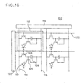
- Fig. 16 shows an example of the configuration of the organic EL panel 102.
- a pixel 112 includes a first switch element 104, a second switch element 106 formed of two thin film transistors, a voltage holding capacity 108 for holding a voltage supplied from the signal line 52, and an organic EL element 110, and ends of signal lines 114 and power source lines 116 are connected to a signal line drive circuit 118, and scanning lines 120 extending in the direction orthogonal to the signal lines 114 and the power source lines 116 are connected to a scanning line drive circuit 122.
- a scanning line drive signal in the ON state is applied to the first switch element 104 via the scanning line 120 by the scanning line drive circuit 122, so that the first switch element 104 is brought into the conducting state.
- a signal line drive signal outputted from the signal line drive circuit 118 is written into the voltage holding capacity 108 via the signal line.
- the conducting state of the second switch element 106 is determined according to the amount of electric charge accumulated in the voltage holding capacity 108, and an electric current is supplied from the power source line 116 to the organic EL element 110 to cause the organic EL element 110 to emit light. Even when the scanning line drive signal is brought into the OFF state, since the voltage which determines the conducting state of the second switch element 106 is accumulated in the voltage holding capacity 108, the electric current is continuously supplied from the power source line 116 to the organic EL element 110.
- a video signal is outputted in the first half of one horizontal scanning period, and a black video signal is outputted in the second half thereof from the signal line drive circuit 118. Then, a scanning line drive signal in the ON state which is in synchronous with the first half of the one horizontal scanning period is applied to the scanning line 120 for writing the video signal and a scanning line drive signal in the ON state which is in synchronous with the second half of the one horizontal scanning period is applied to the scanning line 120 for writing the black video signal, so that the video image display period and the black video image display period of the organic EL panel 102 can be controlled as in the first embodiment.
- the scanning line drive circuit 122 is controlled on the basis of the ratio of black display period determined by the display ratio control unit as in the first embodiment.
- the organic EL panel 102 is a self-light-emitting element, it is necessary to control the brightness of the video image in the period in which the video image is displayed according to the ratio of black display period to make the luminance of the one frame period substantially constant.
- the brightness of the video image is controlled digitally using the signal line drive circuit 118 provided with an output accuracy of 10 bits.
- a state in which the brightness is required in the video image most is a state in which the ratio of black display period becomes the maximum in a predetermined control range. In other words, since the ratio of black display period is large, the period for displaying the video image becomes shorter, and hence the brightness of the video image is required to be increased in order to achieve a substantially constant luminance in the one frame period.
- the maximum number of display tones of the video image at the moment when the highest ratio of black display period is reached in the predetermined range of controlling the ratio of black display period is set to 1020 tones, and the maximum luminance in the video image display period is controlled by reducing the maximum number of display tones of the video image to a smaller value as the ratio of black display period is reduced.
- the brightness during the video image display period can be controlled by obtaining the maximum tone according to the ratio of black display period by Expression 22 and then re-quantizing all the tones in the video image.
- the brightness of the organic EL panel 102 can also be controlled by controlling the current value supplied by the power source lines 116. Therefore, a configuration in which the current value supplied from the power source lines 116 is controlled so as to achieve a substantially constant luminance during one frame period according to the ratio of black display period may also be employed.
- the quality of the displayed input video image can be improved while restraining increase in power consumption by changing the ratio of black display period depending on whether the input video image is a moving image or a still image.
- the ratio of black display period can be stabilized for various video images.
Landscapes
- Engineering & Computer Science (AREA)
- Theoretical Computer Science (AREA)
- Physics & Mathematics (AREA)
- Computer Hardware Design (AREA)
- General Physics & Mathematics (AREA)
- Crystallography & Structural Chemistry (AREA)
- Chemical & Material Sciences (AREA)
- Control Of Indicators Other Than Cathode Ray Tubes (AREA)
- Liquid Crystal Display Device Control (AREA)
- Liquid Crystal (AREA)
- Control Of El Displays (AREA)
- Electroluminescent Light Sources (AREA)
- Transforming Electric Information Into Light Information (AREA)
Applications Claiming Priority (1)
| Application Number | Priority Date | Filing Date | Title |
|---|---|---|---|
| JP2006028924A JP2007206651A (ja) | 2006-02-06 | 2006-02-06 | 画像表示装置及びその方法 |
Publications (2)
| Publication Number | Publication Date |
|---|---|
| EP1816637A2 true EP1816637A2 (de) | 2007-08-08 |
| EP1816637A3 EP1816637A3 (de) | 2008-12-17 |
Family
ID=37964158
Family Applications (1)
| Application Number | Title | Priority Date | Filing Date |
|---|---|---|---|
| EP07250408A Withdrawn EP1816637A3 (de) | 2006-02-06 | 2007-01-31 | Bildanzeigevorrichtung und Bildanzeigeverfahren |
Country Status (5)
| Country | Link |
|---|---|
| US (1) | US20070182700A1 (de) |
| EP (1) | EP1816637A3 (de) |
| JP (1) | JP2007206651A (de) |
| KR (1) | KR100845632B1 (de) |
| CN (1) | CN101017657A (de) |
Cited By (5)
| Publication number | Priority date | Publication date | Assignee | Title |
|---|---|---|---|---|
| WO2011087718A1 (en) * | 2010-01-15 | 2011-07-21 | Atmel Corporation | Control of light-emitting-diode backlight illumination through frame insertion |
| EP2434474A4 (de) * | 2009-05-19 | 2013-03-27 | Sharp Kk | Flüssigkristallanzeigevorrichtung und verfahren zu ihrer ansteuerung |
| US9520411B2 (en) | 2009-11-13 | 2016-12-13 | Semiconductor Energy Laboratory Co., Ltd. | Display device and electronic device including the same |
| US10061172B2 (en) | 2009-10-16 | 2018-08-28 | Semiconductor Energy Laboratory Co., Ltd. | Liquid crystal display device and electronic apparatus having the same |
| WO2019147703A1 (en) | 2018-01-23 | 2019-08-01 | Valve Corporation | Rolling burst illumination for a display |
Families Citing this family (32)
| Publication number | Priority date | Publication date | Assignee | Title |
|---|---|---|---|---|
| KR20050082643A (ko) * | 2004-02-19 | 2005-08-24 | 삼성에스디아이 주식회사 | 액정표시장치의 구동방법 |
| ITTO20050090A1 (it) * | 2005-02-16 | 2006-08-17 | Sim2 Multimedia Spa | Metodo e/o apparato per migliorare la percezione visiva di una immagine visualizzata su uno schermo |
| JP4405481B2 (ja) * | 2006-06-30 | 2010-01-27 | 株式会社東芝 | 液晶表示装置 |
| JP2008268887A (ja) * | 2007-03-29 | 2008-11-06 | Nec Lcd Technologies Ltd | 画像表示装置 |
| US8736535B2 (en) * | 2007-03-29 | 2014-05-27 | Nlt Technologies, Ltd. | Hold type image display system |
| US8259057B2 (en) * | 2007-07-31 | 2012-09-04 | Hewlett-Packard Development Company, L.P. | Liquid crystal display |
| US8135761B2 (en) | 2007-12-10 | 2012-03-13 | Realnetworks, Inc. | System and method for automatically creating a media archive from content on a recording medium |
| US8582954B2 (en) * | 2007-12-10 | 2013-11-12 | Intel Corporation | System and method for automatically creating a media archive from content on a recording medium |
| KR101301769B1 (ko) * | 2007-12-21 | 2013-09-02 | 엘지디스플레이 주식회사 | 액정표시장치와 그 구동방법 |
| JP5365069B2 (ja) * | 2008-05-16 | 2013-12-11 | ソニー株式会社 | 液晶表示装置および液晶表示装置の制御方法 |
| US8555087B2 (en) | 2008-06-19 | 2013-10-08 | Intel Corporation | Systems and methods for content playback and recording |
| JP5315857B2 (ja) * | 2008-08-22 | 2013-10-16 | ソニー株式会社 | 入力装置、制御システム及び制御方法 |
| TWI402812B (zh) * | 2008-10-02 | 2013-07-21 | Chunghwa Picture Tubes Ltd | 驅動電路及液晶顯示器的插灰方法 |
| KR101441307B1 (ko) | 2008-10-10 | 2014-09-17 | 삼성전자주식회사 | 전력 소모 절감을 위한 영상 처리 방법 및 그 장치 |
| JP5202246B2 (ja) | 2008-11-20 | 2013-06-05 | キヤノン株式会社 | 動画像処理装置、及び方法、プログラム |
| WO2010080852A1 (en) * | 2009-01-08 | 2010-07-15 | Dolby Laboratories Licensing Corporation | Universal back light unit control |
| JP4702459B2 (ja) | 2009-01-29 | 2011-06-15 | ソニー株式会社 | 液晶表示装置組立体、及び、液晶表示装置組立体の駆動方法 |
| CN101944351B (zh) * | 2009-07-08 | 2013-08-07 | 宏碁股份有限公司 | 有效显示周期判断装置及方法、分辨率判断系统及方法 |
| US8581941B2 (en) | 2009-10-02 | 2013-11-12 | Panasonic Corporation | Backlight device and display apparatus |
| WO2011089832A1 (en) * | 2010-01-20 | 2011-07-28 | Semiconductor Energy Laboratory Co., Ltd. | Method for driving display device and liquid crystal display device |
| WO2011092732A1 (ja) * | 2010-01-26 | 2011-08-04 | パナソニック株式会社 | 表示装置及びその駆動方法 |
| US9569699B2 (en) | 2010-09-03 | 2017-02-14 | Shenzhen Sensetime Technology Co., Ltd. | System and method for synthesizing portrait sketch from a photo |
| JP5197698B2 (ja) * | 2010-09-07 | 2013-05-15 | 株式会社東芝 | 映像表示装置および情報処理装置 |
| US9916793B2 (en) * | 2012-06-01 | 2018-03-13 | Semiconductor Energy Laboratory Co., Ltd. | Semiconductor device and method of driving the same |
| US9607556B2 (en) | 2012-06-15 | 2017-03-28 | Dolby Laboratories Licensing Corporation | Systems and methods for controlling dual modulation displays |
| JP6343515B2 (ja) * | 2014-07-31 | 2018-06-13 | 株式会社ジャパンディスプレイ | 表示装置 |
| WO2017115208A1 (en) | 2015-12-28 | 2017-07-06 | Semiconductor Energy Laboratory Co., Ltd. | Device, television system, and electronic device |
| CN105807458B (zh) * | 2016-05-20 | 2021-02-26 | 京东方科技集团股份有限公司 | 一种液晶显示面板公共电压的烧录检测方法及装置 |
| CN106409223B (zh) * | 2016-10-28 | 2019-05-31 | 深圳市华星光电技术有限公司 | Oled显示装置的亮度调节方法及oled显示装置 |
| US10692443B2 (en) * | 2017-11-30 | 2020-06-23 | Novatek Microelectronics Corp. | Synchronous backlight device and operation method thereof |
| KR102529152B1 (ko) | 2018-06-05 | 2023-05-04 | 삼성디스플레이 주식회사 | 표시 장치 및 그 구동 방법 |
| KR102680091B1 (ko) * | 2020-04-17 | 2024-07-03 | 삼성디스플레이 주식회사 | 표시 장치 및 그 구동 방법 |
Family Cites Families (12)
| Publication number | Priority date | Publication date | Assignee | Title |
|---|---|---|---|---|
| JP3229250B2 (ja) * | 1997-09-12 | 2001-11-19 | インターナショナル・ビジネス・マシーンズ・コーポレーション | 液晶表示装置における画像表示方法及び液晶表示装置 |
| JP3747768B2 (ja) * | 2000-03-17 | 2006-02-22 | 株式会社日立製作所 | 液晶表示装置 |
| JP4040826B2 (ja) * | 2000-06-23 | 2008-01-30 | 株式会社東芝 | 画像処理方法および画像表示システム |
| US7106350B2 (en) * | 2000-07-07 | 2006-09-12 | Kabushiki Kaisha Toshiba | Display method for liquid crystal display device |
| JP3527193B2 (ja) * | 2000-10-13 | 2004-05-17 | Necエレクトロニクス株式会社 | 液晶表示装置及びコンピュータ |
| JP2002323876A (ja) * | 2001-04-24 | 2002-11-08 | Nec Corp | 液晶表示装置における画像表示方法及び液晶表示装置 |
| KR100778845B1 (ko) * | 2001-12-29 | 2007-11-22 | 엘지.필립스 엘시디 주식회사 | 액정표시장치의 구동방법 |
| JP3703806B2 (ja) * | 2003-02-13 | 2005-10-05 | 三菱電機株式会社 | 画像処理装置、画像処理方法、および画像表示装置 |
| CN1820295A (zh) * | 2003-05-07 | 2006-08-16 | 东芝松下显示技术有限公司 | El显示装置及其驱动方法 |
| US7557801B2 (en) * | 2003-05-16 | 2009-07-07 | Semiconductor Energy Laboratory Co., Ltd. | Display device and driving method thereof |
| JP2006189658A (ja) * | 2005-01-06 | 2006-07-20 | Toshiba Corp | 画像表示装置及びその画像表示方法 |
| JP2006189661A (ja) * | 2005-01-06 | 2006-07-20 | Toshiba Corp | 画像表示装置及びその方法 |
-
2006
- 2006-02-06 JP JP2006028924A patent/JP2007206651A/ja not_active Withdrawn
- 2006-11-16 KR KR1020060113273A patent/KR100845632B1/ko not_active Expired - Fee Related
-
2007
- 2007-01-05 US US11/620,166 patent/US20070182700A1/en not_active Abandoned
- 2007-01-31 EP EP07250408A patent/EP1816637A3/de not_active Withdrawn
- 2007-02-06 CN CNA2007100067853A patent/CN101017657A/zh active Pending
Cited By (10)
| Publication number | Priority date | Publication date | Assignee | Title |
|---|---|---|---|---|
| EP2434474A4 (de) * | 2009-05-19 | 2013-03-27 | Sharp Kk | Flüssigkristallanzeigevorrichtung und verfahren zu ihrer ansteuerung |
| US10061172B2 (en) | 2009-10-16 | 2018-08-28 | Semiconductor Energy Laboratory Co., Ltd. | Liquid crystal display device and electronic apparatus having the same |
| US10310348B2 (en) | 2009-10-16 | 2019-06-04 | Semiconductor Energy Laboratory Co., Ltd. | Liquid crystal display device and electronic apparatus having the same |
| US9520411B2 (en) | 2009-11-13 | 2016-12-13 | Semiconductor Energy Laboratory Co., Ltd. | Display device and electronic device including the same |
| US10332912B2 (en) | 2009-11-13 | 2019-06-25 | Semiconductor Energy Laboratory Co., Ltd. | Display device and electronic device including the same |
| WO2011087718A1 (en) * | 2010-01-15 | 2011-07-21 | Atmel Corporation | Control of light-emitting-diode backlight illumination through frame insertion |
| US8378961B2 (en) | 2010-01-15 | 2013-02-19 | Atmel Corporation | Control of light-emitting-diode backlight illumination through frame insertion |
| US8547323B2 (en) | 2010-01-15 | 2013-10-01 | Atmel Corporation | Control of light-emitting-diode backlight illumination through frame insertion |
| WO2019147703A1 (en) | 2018-01-23 | 2019-08-01 | Valve Corporation | Rolling burst illumination for a display |
| EP3735686A4 (de) * | 2018-01-23 | 2021-09-22 | Valve Corporation | Roll-burst-beleuchtung für eine anzeige |
Also Published As
| Publication number | Publication date |
|---|---|
| CN101017657A (zh) | 2007-08-15 |
| US20070182700A1 (en) | 2007-08-09 |
| KR20070080202A (ko) | 2007-08-09 |
| EP1816637A3 (de) | 2008-12-17 |
| JP2007206651A (ja) | 2007-08-16 |
| KR100845632B1 (ko) | 2008-07-10 |
Similar Documents
| Publication | Publication Date | Title |
|---|---|---|
| EP1816637A2 (de) | Bildanzeigevorrichtung und Bildanzeigeverfahren | |
| US7505026B2 (en) | Image display device and method of displaying image | |
| KR100442304B1 (ko) | 액정 표시 방법 | |
| US8068087B2 (en) | Methods and systems for reduced flickering and blur | |
| US7952556B2 (en) | Liquid crystal display device, driving control circuit and driving method used in same device | |
| CN100545899C (zh) | 液晶显示装置 | |
| KR101169051B1 (ko) | 액정 표시 장치 및 그의 구동 방법 | |
| KR101103889B1 (ko) | 액정표시장치와 그 구동방법 | |
| US8325129B2 (en) | Liquid crystal display and driving method thereof | |
| EP2113903B1 (de) | Gegenlicht-Ansteuerkreis und Ansteuerverfahren dafür | |
| US20080001881A1 (en) | Liquid crystal display and image display method | |
| KR100785553B1 (ko) | 표시 제어 회로, 표시 제어 방법, 및 액정 표시 장치 | |
| US20060119566A1 (en) | Liquid crystal display | |
| US20030048246A1 (en) | Method and apparatus for driving liquid crystal display | |
| KR20040107559A (ko) | 액정표시장치의 구동방법 및 구동장치 | |
| US20090015536A1 (en) | Liquid crystal display apparatus | |
| KR20030048953A (ko) | 액정의 응답속도 측정방법 및 장치 | |
| US20090002310A1 (en) | Liquid crystal display apparatus | |
| US8054321B2 (en) | Display and driving method thereof | |
| US20080198117A1 (en) | Display Device, Liquid Crystal Monitor, Liquid Crystal Television Receiver, and Display Method | |
| JP2005134724A (ja) | 液晶表示装置 | |
| JP2009031755A (ja) | 液晶表示装置 | |
| KR20070120279A (ko) | 액정표시장치와 그 구동방법 | |
| US20190147811A1 (en) | Liquid crystal display device, method for driving liquid crystal panel, and method for setting signal to be written in liquid crystal display device | |
| KR101183399B1 (ko) | 표시장치와 그 구동방법 |
Legal Events
| Date | Code | Title | Description |
|---|---|---|---|
| PUAI | Public reference made under article 153(3) epc to a published international application that has entered the european phase |
Free format text: ORIGINAL CODE: 0009012 |
|
| 17P | Request for examination filed |
Effective date: 20070207 |
|
| AK | Designated contracting states |
Kind code of ref document: A2 Designated state(s): AT BE BG CH CY CZ DE DK EE ES FI FR GB GR HU IE IS IT LI LT LU LV MC NL PL PT RO SE SI SK TR |
|
| AX | Request for extension of the european patent |
Extension state: AL BA HR MK YU |
|
| PUAL | Search report despatched |
Free format text: ORIGINAL CODE: 0009013 |
|
| AK | Designated contracting states |
Kind code of ref document: A3 Designated state(s): AT BE BG CH CY CZ DE DK EE ES FI FR GB GR HU IE IS IT LI LT LU LV MC NL PL PT RO SE SI SK TR |
|
| AX | Request for extension of the european patent |
Extension state: AL BA HR MK RS |
|
| RIC1 | Information provided on ipc code assigned before grant |
Ipc: G09G 3/34 20060101ALI20081107BHEP Ipc: G09G 3/20 20060101AFI20081107BHEP |
|
| 17Q | First examination report despatched |
Effective date: 20090304 |
|
| AKX | Designation fees paid |
Designated state(s): DE FR GB |
|
| STAA | Information on the status of an ep patent application or granted ep patent |
Free format text: STATUS: THE APPLICATION IS DEEMED TO BE WITHDRAWN |
|
| 18D | Application deemed to be withdrawn |
Effective date: 20090715 |