EP1816727A2 - Moteur électrique - Google Patents
Moteur électrique Download PDFInfo
- Publication number
- EP1816727A2 EP1816727A2 EP20070001240 EP07001240A EP1816727A2 EP 1816727 A2 EP1816727 A2 EP 1816727A2 EP 20070001240 EP20070001240 EP 20070001240 EP 07001240 A EP07001240 A EP 07001240A EP 1816727 A2 EP1816727 A2 EP 1816727A2
- Authority
- EP
- European Patent Office
- Prior art keywords
- bearing
- plastic
- motor
- stator
- injection molding
- Prior art date
- Legal status (The legal status is an assumption and is not a legal conclusion. Google has not performed a legal analysis and makes no representation as to the accuracy of the status listed.)
- Withdrawn
Links
- 239000006223 plastic coating Substances 0.000 claims abstract description 22
- 238000003475 lamination Methods 0.000 claims abstract description 15
- 238000004519 manufacturing process Methods 0.000 claims abstract description 4
- 238000005096 rolling process Methods 0.000 claims description 14
- 238000001746 injection moulding Methods 0.000 claims description 11
- 238000002347 injection Methods 0.000 claims description 9
- 239000007924 injection Substances 0.000 claims description 9
- 238000004804 winding Methods 0.000 claims description 8
- 238000000034 method Methods 0.000 claims description 6
- 230000005291 magnetic effect Effects 0.000 claims description 3
- 229910000906 Bronze Inorganic materials 0.000 claims description 2
- 239000010974 bronze Substances 0.000 claims description 2
- 230000006835 compression Effects 0.000 claims description 2
- 238000007906 compression Methods 0.000 claims description 2
- KUNSUQLRTQLHQQ-UHFFFAOYSA-N copper tin Chemical compound [Cu].[Sn] KUNSUQLRTQLHQQ-UHFFFAOYSA-N 0.000 claims description 2
- 238000005507 spraying Methods 0.000 claims description 2
- 230000001419 dependent effect Effects 0.000 description 2
- 238000012986 modification Methods 0.000 description 2
- 230000004048 modification Effects 0.000 description 2
- 238000003825 pressing Methods 0.000 description 2
- 238000003860 storage Methods 0.000 description 2
- 229910000831 Steel Inorganic materials 0.000 description 1
- 238000011161 development Methods 0.000 description 1
- 230000018109 developmental process Effects 0.000 description 1
- 230000000694 effects Effects 0.000 description 1
- 230000005294 ferromagnetic effect Effects 0.000 description 1
- 230000005415 magnetization Effects 0.000 description 1
- 125000006850 spacer group Chemical group 0.000 description 1
- 239000010959 steel Substances 0.000 description 1
Images


Classifications
-
- H—ELECTRICITY
- H02—GENERATION; CONVERSION OR DISTRIBUTION OF ELECTRIC POWER
- H02K—DYNAMO-ELECTRIC MACHINES
- H02K5/00—Casings; Enclosures; Supports
- H02K5/04—Casings or enclosures characterised by the shape, form or construction thereof
- H02K5/16—Means for supporting bearings, e.g. insulating supports or means for fitting bearings in the bearing-shields
- H02K5/173—Means for supporting bearings, e.g. insulating supports or means for fitting bearings in the bearing-shields using bearings with rolling contact, e.g. ball bearings
- H02K5/1735—Means for supporting bearings, e.g. insulating supports or means for fitting bearings in the bearing-shields using bearings with rolling contact, e.g. ball bearings radially supporting the rotary shaft at only one end of the rotor
-
- F—MECHANICAL ENGINEERING; LIGHTING; HEATING; WEAPONS; BLASTING
- F04—POSITIVE - DISPLACEMENT MACHINES FOR LIQUIDS; PUMPS FOR LIQUIDS OR ELASTIC FLUIDS
- F04D—NON-POSITIVE-DISPLACEMENT PUMPS
- F04D25/00—Pumping installations or systems
- F04D25/02—Units comprising pumps and their driving means
- F04D25/06—Units comprising pumps and their driving means the pump being electrically driven
- F04D25/0606—Units comprising pumps and their driving means the pump being electrically driven the electric motor being specially adapted for integration in the pump
- F04D25/0613—Units comprising pumps and their driving means the pump being electrically driven the electric motor being specially adapted for integration in the pump the electric motor being of the inside-out type, i.e. the rotor is arranged radially outside a central stator
- F04D25/062—Details of the bearings
-
- F—MECHANICAL ENGINEERING; LIGHTING; HEATING; WEAPONS; BLASTING
- F04—POSITIVE - DISPLACEMENT MACHINES FOR LIQUIDS; PUMPS FOR LIQUIDS OR ELASTIC FLUIDS
- F04D—NON-POSITIVE-DISPLACEMENT PUMPS
- F04D25/00—Pumping installations or systems
- F04D25/02—Units comprising pumps and their driving means
- F04D25/06—Units comprising pumps and their driving means the pump being electrically driven
- F04D25/0606—Units comprising pumps and their driving means the pump being electrically driven the electric motor being specially adapted for integration in the pump
- F04D25/0613—Units comprising pumps and their driving means the pump being electrically driven the electric motor being specially adapted for integration in the pump the electric motor being of the inside-out type, i.e. the rotor is arranged radially outside a central stator
- F04D25/0646—Details of the stator
-
- H—ELECTRICITY
- H02—GENERATION; CONVERSION OR DISTRIBUTION OF ELECTRIC POWER
- H02K—DYNAMO-ELECTRIC MACHINES
- H02K1/00—Details of the magnetic circuit
- H02K1/06—Details of the magnetic circuit characterised by the shape, form or construction
- H02K1/12—Stationary parts of the magnetic circuit
- H02K1/18—Means for mounting or fastening magnetic stationary parts on to, or to, the stator structures
- H02K1/187—Means for mounting or fastening magnetic stationary parts on to, or to, the stator structures to inner stators
Definitions
- the invention relates to an electronically commutated motor, in particular a small or micro motor.
- Such motors are preferably used in small and micro fans.
- the fans of the ebm-papst 250 series have dimensions of 8 x 25 x 25 mm and a weight of approximately 5 g.
- the dimensions are 20 x 40 x 40 mm and the weight is less than 30 g.
- the engines are correspondingly even smaller and weigh even less.
- the assembly must be simple and uncomplicated to allow cost-effective production by a high degree of automation.
- this object is achieved by an engine according to claim 1 and a method according to claim 22.
- a motor can be very compact and allows operation at high speeds, ie high power.
- the terms left, right, up and down refer to the respective drawing figure, and may vary from one drawing figure to the next, depending on a particular orientation (portrait or landscape). Identical or equivalent parts are denoted by the same reference numerals in the various figures and usually described only once.
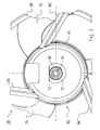
- Fig. 1 shows a longitudinal section through an axial fan 20 with a motor 21 according to a preferred embodiment of the invention on a greatly enlarged scale with an approximately five times magnification.
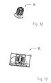
- the fan 20 in FIG. 13 is shown by way of example on a scale of approximately 1: 1.
- the motor 21 is arranged in an air guide tube 80 and has an outer rotor 22 and an inner stator 50.
- the outer rotor 22 has a rotor bell 24, on whose outer circumference a fan 23 with fan blades 26 is provided.
- a rotor magnet 28 is fixed on a soft ferromagnetic return element 27, which is e.g. can be magnetized four-pole.
- the rotor bell 24 has a bottom 30 in which an upper shaft end 32 of a rotor shaft 34 is fixed, which has a lower, free shaft end 35.
- the shaft 34 is made of steel and the rotor bell 24 made of plastic.
- the rotor bell 34 is fixed by plastic injection at the upper end of the shaft 32.
- the inner stator 50 which is described in detail in FIGS. 2 to 11, has a laminated stator core 52 with a plastic coating 77, which together form a bearing tube 70 for the rotatable mounting of the rotor shaft 34.
- a plastic part 90 'in the form of a first axial extension of the plastic coating 77 with a bearing 72 is arranged at one end 71' of the laminated stator core 52.
- a plastic part 90" in the form of a second axial extension is arranged, in which a bearing 76 is located.
- the plastic coating 77 and the projections 90 'and 90 " are made in one piece, with the bearing 72 being secured by plastic spraying in the extension 90' and held in a form-fitting manner by this
- the extension 90 ' can be produced independently of the plastic coating 77 and can be attached to it in a simple operation, for example
- the bearing 76 may also be optionally injected into or pressed into the extension 90 ".
- the bearings 72 and 76 are preferably designed as rolling bearings, but not limited to a particular type of bearing. Rather, different types of bearings can be used, eg plain bearings.
- the rolling bearing 72 has an inner ring 72 'and an outer ring 72 ", and the rolling bearing 76 has an inner ring 76' and an outer ring 76".
- the rotatably mounted in the rolling bearings 72 and 76 rotor shaft 34 is held there by a support member or securing element 92 and a compression spring 94.
- the support member 92 such as a snap-action disc or other locking member is engaged at the lower end 35 of the shaft 34 in an annular groove.
- the spring 94 is clamped between the inner ring 72 'of the rolling bearing 72 and the locking member 92. Through them, a conical extension of the bottom 30 of the rotor bell 24 is pressed against the inner ring 76 'of the rolling bearing 76, so that the shaft 34 in the rolling bearings 72 and 76 of the inner stator 50th is strained. This effect of the spring 94 is assisted by the fact that the rotor magnet 28 is offset against the stator lamination 52 down, creating a magnetic train on the outer rotor 22, which pulls it upwards.
- a printed circuit board 46 is arranged with a relatively large electronic component 48, e.g. a MOSFET which is provided for controlling the current in a stator winding 97 of the motor 21.
- a relatively large electronic component 48 e.g. a MOSFET which is provided for controlling the current in a stator winding 97 of the motor 21.
- Other electronic components e.g. a Hall IC, may also be arranged on the printed circuit board 46, to which connection elements 96 for the stator winding 97 are soldered. These connection elements 96 are fixed by plastic injection in a shoulder 95 of the extension 90 '.
- the lower end of the extension 90 ' is connected by pressing with a hub 85 and may additionally glued to this and / or welded. From this hub 85 go out webs 86 'and 86 ", which hold the Heilleitrohr 80.
- Fig. 2 shows a plan view of the hub 85 of the fan 20 of Fig. 1.
- Fig. 2 illustrates the arranged between the hub 85 and the shipsleitrohr 80 webs 86 ', 86 "and 86"', and the extension 90 ', whose free end is connected to the hub 85.
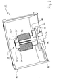
- FIG. 3 shows a perspective longitudinal section through the air duct 80 of the fan 20 with a perspective view of the inner stator 50.
- FIG. 3 illustrates the mounting of the fan 20 according to a preferred embodiment, in which the circuit board 46 with the component 48 in a first step the inner stator 50 is placed before it is attached to the hub 85 in a further step.
- the inner stator 50 has, by way of example, four spacers 59 ', 59 “, 59"', 59 “”. These serve to prevent damage to the stator winding 97 when the inner stator 50 is pressed into the hub 85.
- FIG. 4 shows a spatial representation of the inner stator 50 (FIG. 3) at approximately a tenfold magnification.
- the inner stator 50 is shown in FIG. 12 by way of example on a scale of approximately 1: 1.
- FIG. 4 shows the printed circuit board 46 abutting the shoulder 95 of the extension 90 ', to which the connecting element 96' is soldered, and also the roller bearing 76 fastened in the extension 90 ".
- FIG. this has at its upper end two recesses 75 'and 75 ".
- the laminated stator core 52 includes sheets, three of which are designated 55 ', 55 "and 55"'.
- the stator lamination stack 52 is "packetized", i. its sheets have small holes that are embossed so that they form a unitary block.
- plastic plastic coating 77 contribute, which is injected into the stator lamination 52 and forms together with this the bearing tube 70.
- this plastic forms strip-shaped plastic supports 79 at locations on the outside of the laminated core 52 - two plastic supports are designated by way of example with 79 'and 79 "- which further increase the strength.
- the laminated stator core 52 has, according to FIG. 9, distinct stator poles 52 ', 52 “, 52"', 52 “” which are separated from one another by grooves 54 ', 54 “, 54"', 54 “”, through which the plastic coating 77 extends.
- the stator winding 97 is arranged, see. Fig. 4.
- Fig. 5 shows a side view of the inner stator 50 of Fig. 4, but without the winding 97, and illustrates the shoulder 95 of the extension 90 ', in which the connection element 96' is fixed. In the region of the extension 90 ', in which the component 48 is arranged on the printed circuit board 46, this has a recess 99th
- FIG. 6 shows a longitudinal section through the inner stator 50 and illustrates the recess 99 as well as the bearing tube 70 formed by the plastic coating 77 and the laminated stator core 52.
- the plastic coating 77 forms at the lower end 71 'of the laminated stator core 52 an end layer 73', on which the axial extension 90 'is arranged.
- This has a recess 91 in which the rolling bearing 72 is arranged.
- the recess 91 has a first shoulder 91 'and a second shoulder 91 "opposite the first shoulder
- at least the outer ring 72" of this rolling bearing 72 is injected into the plastic of the extension 90'.
- a first tool is guided from above through the stator lamination stack 52, which holds the upper edge of this outer ring 72 "in front of the plastic injection molding, and its lower edge is held fast by a second tool coming from below. that during plastic injection no plastic can penetrate into the bearing 72.
- the plastic coating 77 forms an end layer or end plate 73" on which the axial extension 90 "is arranged. As can be seen from Fig. 6, the plastic coating 77 and the extensions 90 'and 90" are preferably in one piece educated.
- the extension 90 has a recess 93 for receiving the roller bearing 76. This is preferably pressed into the recess 93, see Fig. 7.
- FIG. 7 shows a sectional view of the inner stator 50 with both rolling bearings 72 and 76.
- FIG. 8 shows another side view of the inner stator 50 analogously to FIG. 5.
- the inner stator 50 is rotated 45 ° to the right in FIG. 8 and shown without the printed circuit board 46 and the component 48.
- These are preferably designed as bronze pins.
- FIG. 9 shows a plan view of the inner stator 50.
- FIG. 9 shows a preferred embodiment of the laminated stator core 52 provided with the plastic coating 77 and illustrates the grooves 54 'provided between the poles 52', 52 ", 52 '" and 52 “' thereof. 54 ", 54"'and 54 "”.
- the final layer 73 'of the plastic coating 77 has at the axial ends of the grooves 54', 54 ", 54" 'and 54 "” apertures 56', 56 ", 56 '” and 56 "”.
- the end layer 73 'lying opposite the end layer 73' has openings 58 ', 58 ", 58"' and 58 ".” These openings on both sides make it possible to arrange the stator winding 97 on the stator lamination stack 52 (not shown in FIG.
- poles 52 ', 52 ", 52'” and 52 “” have an identical structure. For simplicity, therefore, only the structure of the pole 52 'will be described.
- This has a pole core 12 and a pole piece with pole ends or pole horns 14, 16.
- the pole piece 16, on which the plastic support 79 'is applied, has a smaller diameter than the pole piece 14.
- This design is commonly referred to as a reluctance cut and is used to produce a so-called reluctance torque.
- the rotor magnet 28 has a trapezoidal magnetization for cooperation with this stator shape.
- Fig. 10 shows a sectional view of the inner stator 50 along the section line XX of Fig. 9, and Fig. 11 shows a sectional view of the inner stator 50 along the section line XI-XI of Fig. 9.
- Fig. 11 illustrates the openings 56 ', 56'"in the end layer 73 'at the end 71' of the laminated core 52, as well as the openings 58 ', 58"' in the final layer 73 "at the end 71".
- the fan as shown in Fig. 13, can be operated by the described type of storage at a speed of 15,000 rev / min.
- the invention preferably relates to an electronically commutated motor (21) which comprises: a permanent magnetic outer rotor (22) having a rotor shaft (34); an inner stator (50) having a stator lamination stack (52) having stator poles (52 ', 52 “, 52"', 52 “") between which slots (54 ', 54 ", 54”', 54 “") are interposed are; a plastic coating (77) which extends through the grooves (54 ', 54 ", 54”', 54 “"), which together with the stator lamination stack (52) has a bearing tube (70) for receiving at least one bearing (72, 76 ) for supporting the rotor shaft (34), and which for the storage of the rotor shaft (34) has a first axial extension (90 ') in which a first bearing (72) is fixed by plastic injection.
- the plastic injection-molded connection preferably has a first shoulder (91 ') and a second shoulder (91 ") for fastening the first bearing (72).
Landscapes
- Engineering & Computer Science (AREA)
- Mechanical Engineering (AREA)
- General Engineering & Computer Science (AREA)
- Power Engineering (AREA)
- Iron Core Of Rotating Electric Machines (AREA)
- Motor Or Generator Frames (AREA)
- Connection Of Motors, Electrical Generators, Mechanical Devices, And The Like (AREA)
Applications Claiming Priority (1)
| Application Number | Priority Date | Filing Date | Title |
|---|---|---|---|
| DE202006002068 | 2006-02-03 |
Publications (2)
| Publication Number | Publication Date |
|---|---|
| EP1816727A2 true EP1816727A2 (fr) | 2007-08-08 |
| EP1816727A3 EP1816727A3 (fr) | 2011-04-06 |
Family
ID=37864492
Family Applications (1)
| Application Number | Title | Priority Date | Filing Date |
|---|---|---|---|
| EP20070001240 Withdrawn EP1816727A3 (fr) | 2006-02-03 | 2007-01-20 | Moteur électrique |
Country Status (2)
| Country | Link |
|---|---|
| US (1) | US7859145B2 (fr) |
| EP (1) | EP1816727A3 (fr) |
Cited By (5)
| Publication number | Priority date | Publication date | Assignee | Title |
|---|---|---|---|---|
| EP3141749A4 (fr) * | 2014-05-07 | 2017-05-31 | Panasonic Corporation | Compresseur étanche et dispositif de réfrigération |
| EP3910199A1 (fr) * | 2020-05-15 | 2021-11-17 | Quanta Computer Inc. | Module de ventilateur et moteur |
| US11437900B2 (en) | 2019-12-19 | 2022-09-06 | Black & Decker Inc. | Modular outer-rotor brushless motor for a power tool |
| US11757330B2 (en) | 2019-12-19 | 2023-09-12 | Black & Decker, Inc. | Canned outer-rotor brushless motor for a power tool |
| US12176794B2 (en) | 2021-11-19 | 2024-12-24 | Black & Decker Inc. | Outer-rotor brushless motor for a power tool |
Families Citing this family (11)
| Publication number | Priority date | Publication date | Assignee | Title |
|---|---|---|---|---|
| EP1816727A3 (fr) * | 2006-02-03 | 2011-04-06 | ebm-papst St. Georgen GmbH & Co. KG | Moteur électrique |
| TWI340797B (en) * | 2007-08-24 | 2011-04-21 | Delta Electronics Inc | Fan, motor and bush thereof |
| JP5472683B2 (ja) * | 2009-05-11 | 2014-04-16 | 日立工機株式会社 | 電動工具 |
| US8283841B2 (en) * | 2010-06-23 | 2012-10-09 | Lin Engineering | Motor end cap with interference fit |
| US9866078B2 (en) | 2014-01-29 | 2018-01-09 | Black & Decker Inc. | Brush assembly mount |
| US9991770B2 (en) | 2013-08-09 | 2018-06-05 | Black & Decker Inc. | Spring post for brush card for a power tool |
| US20150042189A1 (en) | 2013-08-09 | 2015-02-12 | Black & Decker Inc. | Brush assembly for an electric motor |
| DE102013227054A1 (de) * | 2013-12-23 | 2015-06-25 | Robert Bosch Gmbh | Stator mit einer Umspritzung und elektrische Maschine mit dem Stator |
| WO2016006229A1 (fr) * | 2014-07-07 | 2016-01-14 | パナソニックIpマネジメント株式会社 | Compresseur hermétique, et dispositif de réfrigération mettant en œuvre celui-ci |
| US10218243B2 (en) * | 2014-09-09 | 2019-02-26 | Top Co., Ltd. | Motor structure for electrolytic corrosion protection of bearing |
| WO2025235038A1 (fr) * | 2024-05-09 | 2025-11-13 | Whisper Aero Inc. | Stator aérodynamique conducteur |
Citations (1)
| Publication number | Priority date | Publication date | Assignee | Title |
|---|---|---|---|---|
| US20020113519A1 (en) | 2001-02-22 | 2002-08-22 | Brown Fred A. | Stator with molded insulator |
Family Cites Families (23)
| Publication number | Priority date | Publication date | Assignee | Title |
|---|---|---|---|---|
| US3200269A (en) * | 1961-01-31 | 1965-08-10 | Melvin M Goldstein | Self charging nuclear battery |
| DE3123814A1 (de) * | 1980-07-22 | 1982-04-01 | VEB Elektromotorenwerk Hartha, DDR 7302 Hartha | Staenderaufbau fuer kleine elektrische maschinen, insbesondere elektronikmotoren |
| US4604665A (en) * | 1980-12-05 | 1986-08-05 | Papst-Motoren Gmbh & Co. Kg | Driving mechanism for magnetic hard disc |
| DE3404466A1 (de) * | 1984-02-08 | 1985-08-08 | Ebm Elektrobau Mulfingen Gmbh & Co, 7119 Mulfingen | Aussenlaeufermotor |
| US4682065A (en) * | 1985-11-13 | 1987-07-21 | Nidec-Torin Corporation | Molded plastic motor housing with integral stator mounting and shaft journalling projection |
| DE3809277B4 (de) * | 1987-09-21 | 2005-02-24 | Papst Licensing Gmbh & Co. Kg | Lageranordnung für axial kompakten Kleinstventilator |
| US5170086A (en) * | 1987-12-10 | 1992-12-08 | Papst Motoren Gmbh | Electric motor with toothed disk to secure stator core |
| US4934041A (en) * | 1988-07-27 | 1990-06-19 | Nidec Corporation | Method of assembling brushless electric motors |
| TW263629B (fr) * | 1992-05-27 | 1995-11-21 | Nihon Densan Kk | |
| US5682074A (en) * | 1994-03-02 | 1997-10-28 | Northrop Grumman Corporation | Electric vehicle motor |
| US5770907A (en) * | 1995-08-14 | 1998-06-23 | Itt Automotive Electrical Systems, Inc. | Windshield wiper motor for use in a vehicle and method for manufacturing |
| US5666011A (en) * | 1995-09-08 | 1997-09-09 | Hong; Ching-Shen | Miniature fan motor assembly |
| DE59913902D1 (de) * | 1998-03-21 | 2006-11-23 | Ebm Papst St Georgen Gmbh & Co | Elektronisch kommutierter Motor |
| US6050786A (en) * | 1998-08-19 | 2000-04-18 | Delta Electronics, Inc. | Heat dissipation structure of a fan unit |
| DE29914693U1 (de) * | 1998-09-01 | 2000-01-13 | Papst Motoren Gmbh & Co Kg | Axiallüfter mit einem Aussenläufer-Antriebsmotor |
| US6318976B1 (en) * | 2000-04-10 | 2001-11-20 | Hsieh Hsin-Mao | Heat dissipation fan |
| DE10052039C2 (de) * | 2000-10-20 | 2002-10-31 | Ebm Werke Gmbh & Co Kg | Axiale Wellensicherung und Sicherungselement |
| CA2441622C (fr) * | 2001-03-16 | 2010-06-08 | Altech Generating Systems Llc | Alternateur et procede de fabrication dudit alternateur |
| JP2004040926A (ja) * | 2002-07-04 | 2004-02-05 | Minebea Co Ltd | ファンモータ |
| CA2463149C (fr) * | 2002-08-30 | 2010-05-25 | Ebm-Papst St. Georgen Gmbh & Co. Kg | Dispositif pourvu d'un palier lisse |
| DE20301009U1 (de) * | 2003-01-23 | 2004-05-27 | Papst-Motoren Gmbh & Co. Kg | Außenläufermotor, insbesondere Klein- oder Kleinstlüfter |
| US7841541B2 (en) * | 2003-11-12 | 2010-11-30 | Ebm-Papst St. Georgen Gmbh & Co. Kg | Fan having a sensor |
| EP1816727A3 (fr) * | 2006-02-03 | 2011-04-06 | ebm-papst St. Georgen GmbH & Co. KG | Moteur électrique |
-
2007
- 2007-01-20 EP EP20070001240 patent/EP1816727A3/fr not_active Withdrawn
- 2007-01-30 US US11/668,508 patent/US7859145B2/en not_active Expired - Fee Related
Patent Citations (1)
| Publication number | Priority date | Publication date | Assignee | Title |
|---|---|---|---|---|
| US20020113519A1 (en) | 2001-02-22 | 2002-08-22 | Brown Fred A. | Stator with molded insulator |
Cited By (8)
| Publication number | Priority date | Publication date | Assignee | Title |
|---|---|---|---|---|
| EP3141749A4 (fr) * | 2014-05-07 | 2017-05-31 | Panasonic Corporation | Compresseur étanche et dispositif de réfrigération |
| US10001116B2 (en) | 2014-05-07 | 2018-06-19 | Panasonic Corporation | Sealed compressor and refrigeration device |
| US11437900B2 (en) | 2019-12-19 | 2022-09-06 | Black & Decker Inc. | Modular outer-rotor brushless motor for a power tool |
| US11757330B2 (en) | 2019-12-19 | 2023-09-12 | Black & Decker, Inc. | Canned outer-rotor brushless motor for a power tool |
| US12218567B2 (en) | 2019-12-19 | 2025-02-04 | Black & Decker Inc. | Power tool having an outer-rotor brushless motor |
| EP3910199A1 (fr) * | 2020-05-15 | 2021-11-17 | Quanta Computer Inc. | Module de ventilateur et moteur |
| CN113669272A (zh) * | 2020-05-15 | 2021-11-19 | 广达电脑股份有限公司 | 风扇模块和马达 |
| US12176794B2 (en) | 2021-11-19 | 2024-12-24 | Black & Decker Inc. | Outer-rotor brushless motor for a power tool |
Also Published As
| Publication number | Publication date |
|---|---|
| EP1816727A3 (fr) | 2011-04-06 |
| US7859145B2 (en) | 2010-12-28 |
| US20070182261A1 (en) | 2007-08-09 |
Similar Documents
| Publication | Publication Date | Title |
|---|---|---|
| EP1816727A2 (fr) | Moteur électrique | |
| DE102004017157B4 (de) | Verfahren zur Herstellung einer Rotoranordnung und Rotoranordnung für eine elektrische Maschine | |
| EP1620932B1 (fr) | Machine electrique | |
| DE102008026648B4 (de) | Rotor für einen elektronisch kommutierten Elektromotor, Verfahren zur Herstellung eines solchen Rotors sowie bei der Herstellung eines solchen Rotors verwendbares Zwischenprodukt | |
| DE102012021042A1 (de) | Rotor und Motor | |
| DE102008032844A1 (de) | Permanentmagnetischer Rotor | |
| WO2007033857A1 (fr) | Module de dent pour partie primaire d'une machine electrique excitee par des aimants permanents | |
| EP2084806A1 (fr) | Moteur électrique et procédé de fabrication d'un moteur électrique pour un servomoteur automobile | |
| DE102012013879A1 (de) | Innenläufermotor | |
| DE102004017507A1 (de) | Rotoranordnung für eine elektrische Maschine | |
| EP1657801A2 (fr) | Rotor pour une machine électrique et procédé de fabrication d'un rotor | |
| EP3189582B1 (fr) | Rotor d'une machine électrique, machine électrique et procédé de fabrication du rotor d'une machine électrique | |
| DE112014007129T5 (de) | Statorkern für eine elektrische Rotationsmaschine, elektrische Rotationsmaschine und Verfahren zur Herstellung einer elektrischen Rotationsmaschine | |
| DE112016006720T5 (de) | Stator, Motor, Gebläse, Staubsauger und Verfahren zum Befestigen eines Hallsensors | |
| DE102017103619A1 (de) | Elektromotor, Innenrotor und Rotorblech | |
| AT522826A1 (de) | Rotor | |
| WO2013164164A2 (fr) | Positionnement d'un aimant permanent dans un rotor ou dans un stator | |
| EP2393186A2 (fr) | Moteur électrique | |
| DE102015121102A1 (de) | Rotorvorrichtung für einen Elektromotor und/oder Generator, Rotor und Motor mit einer solchen Rotorvorrichtung sowie Herstellungsverfahren | |
| DE102009003228B4 (de) | Elektrische Maschine | |
| DE102005047771A1 (de) | Rotoranordnung für eine elektrische Maschine und Verfahren zum Herstellen der Rotoranordnung | |
| WO2013053537A2 (fr) | Rotor ou stator muni d'aimants permanents montés en direction radiale | |
| EP2704294A1 (fr) | Rotor d'une machine synchrone à excitation permanente | |
| DE102011084425A1 (de) | Rotorblechpaket, Rotor und Verfahren zur Herstellung eines Rotorblechpakets | |
| DE102020102457B4 (de) | Elektrische Maschine mit durch Klemmen fixierter Rotormagnete; sowie Verfahren zur Montage eines Rotors |
Legal Events
| Date | Code | Title | Description |
|---|---|---|---|
| PUAI | Public reference made under article 153(3) epc to a published international application that has entered the european phase |
Free format text: ORIGINAL CODE: 0009012 |
|
| AK | Designated contracting states |
Kind code of ref document: A2 Designated state(s): AT BE BG CH CY CZ DE DK EE ES FI FR GB GR HU IE IS IT LI LT LU LV MC NL PL PT RO SE SI SK TR |
|
| AX | Request for extension of the european patent |
Extension state: AL BA HR MK YU |
|
| PUAL | Search report despatched |
Free format text: ORIGINAL CODE: 0009013 |
|
| AK | Designated contracting states |
Kind code of ref document: A3 Designated state(s): AT BE BG CH CY CZ DE DK EE ES FI FR GB GR HU IE IS IT LI LT LU LV MC NL PL PT RO SE SI SK TR |
|
| AX | Request for extension of the european patent |
Extension state: AL BA HR MK RS |
|
| 17P | Request for examination filed |
Effective date: 20110730 |
|
| AKX | Designation fees paid |
Designated state(s): AT BE BG CH CY CZ DE DK EE ES FI FR GB GR HU IE IS IT LI LT LU LV MC NL PL PT RO SE SI SK TR |
|
| 17Q | First examination report despatched |
Effective date: 20121106 |
|
| RIC1 | Information provided on ipc code assigned before grant |
Ipc: H02K 5/173 20060101ALI20150217BHEP Ipc: F04D 25/06 20060101ALI20150217BHEP Ipc: H02K 1/18 20060101AFI20150217BHEP |
|
| GRAP | Despatch of communication of intention to grant a patent |
Free format text: ORIGINAL CODE: EPIDOSNIGR1 |
|
| INTG | Intention to grant announced |
Effective date: 20150515 |
|
| RIN1 | Information on inventor provided before grant (corrected) |
Inventor name: RAPP, NILS Inventor name: BERROTH, HANSJOERG |
|
| STAA | Information on the status of an ep patent application or granted ep patent |
Free format text: STATUS: THE APPLICATION IS DEEMED TO BE WITHDRAWN |
|
| 18D | Application deemed to be withdrawn |
Effective date: 20150926 |