EP1816954B1 - Dispositif de constriction de volume de manchon - Google Patents
Dispositif de constriction de volume de manchon Download PDFInfo
- Publication number
- EP1816954B1 EP1816954B1 EP05852692A EP05852692A EP1816954B1 EP 1816954 B1 EP1816954 B1 EP 1816954B1 EP 05852692 A EP05852692 A EP 05852692A EP 05852692 A EP05852692 A EP 05852692A EP 1816954 B1 EP1816954 B1 EP 1816954B1
- Authority
- EP
- European Patent Office
- Prior art keywords
- blood pressure
- cuff
- volume
- hollow member
- constraining device
- Prior art date
- Legal status (The legal status is an assumption and is not a legal conclusion. Google has not performed a legal analysis and makes no representation as to the accuracy of the status listed.)
- Expired - Lifetime
Links
Images





Classifications
-
- A—HUMAN NECESSITIES
- A61—MEDICAL OR VETERINARY SCIENCE; HYGIENE
- A61B—DIAGNOSIS; SURGERY; IDENTIFICATION
- A61B5/00—Measuring for diagnostic purposes; Identification of persons
- A61B5/02—Detecting, measuring or recording for evaluating the cardiovascular system, e.g. pulse, heart rate, blood pressure or blood flow
- A61B5/021—Measuring pressure in heart or blood vessels
- A61B5/022—Measuring pressure in heart or blood vessels by applying pressure to close blood vessels, e.g. against the skin; Ophthalmodynamometers
- A61B5/02233—Occluders specially adapted therefor
Definitions
- This invention relates to non-invasive blood pressure monitoring devices, systems, and methods and more particularly to systems, methods, and devices for volumetrically constraining blood pressure cuffs.
- Non-invasive blood pressure (“NIBP”) monitors typically require periodic testing to validate whether they are operating correctly. This requirement may be met by using a simulator to generate pressure signals that approximate those created by a patient's arm in surface contact with a blood pressure cuff. In some applications of a simulator to an NIBP, the cuff may wrap on itself, which may result in a larger than ideal volume. The accuracy of the pressure pulse simulation is enhanced if the cuff volume is constrained to approximately match the volume it would otherwise displace if applied to an actual patient's arm.
- One attempt at constraining the expansion of the cuff in a simulated condition has the cuff wrapped around a rigid article often termed a mandrel and having a diameter of the average or typical patient's arm.
- the cuff When a mandrel is used to simulate the geometry of the average or typical patient's arm, the cuff is wrapped around the mandrel such that a surface of the cuff contacts the mandrel in the same manner as it would a patient's arm.
- the present invention comprises a system according to claim 1.
- An arrangement comprises a system for testing a non-invasive blood pressure measurement device.
- This system includes a blood pressure monitor, a blood pressure cuff, a blood pressure simulator, and a cuff volume constraining element that comprises at least one hollow member.
- the blood pressure monitor, the blood pressure cuff, and the blood pressure simulator are pneumatically connected during testing and the blood pressure cuff is placed inside a cuff volume area in the at least one hollow member as a and thereby limit the maximal diameter and maximal volume to which the blood pressure cuff may expand during testing.
- the present invention comprises a method according to claim 7.
- Another arrangement is an apparatus having an aperture for receiving a blood pressure cuff and constraining the volumetric expansion of the blood pressure cuff while testing a pneumatically coupled non-invasive blood pressure measurement device.
- the exemplary apparatus further comprises at least one sheet of flexible and substantially inelastic material connected at a first longitudinal end to a second longitudinal end.
- the present invention in its several embodiments includes a device for constraining cuff volume during NIBP simulation.
- the cuff volume constraining device or element comprise a flexible inelastic hollow cylindrical member which is placed outside the outer surface of a blood pressure cuff.
- the blood pressure cuff is connected pneumatically to a blood pressure simulator and a blood pressure monitor.
- the blood pressure cuff inflates inside or within the constraining bounds of the cuff volume constraining device until the outside diameter of the blood pressure cuff matches the inside diameter of the cuff volume constraining device. This limits the volume of the blood pressure cuff to the volume of the cuff volume constraining device.
- the cuff volume constraining device When not in operation, the cuff volume constraining device, which may be a flexible inelastic hollow cylindrical member, may be folded or rolled for compact storage. Other mechanisms to facilitate portability, such as crumpling the cuff volume constraining device to fit into a small space, may also be done.
- the cuff volume constraining device may be made of a sheet of flexible material nylon fabric, which may be rolled or folded to fit in compact spaces, the sheet of flexible material may be fixedly attached to itself, for example by bringing the two ends in layered proximity and creating a seam, via stitching, fusing, or an adhesive for example, to form a tube or a cylinder.
- This sheet of material may include a number of pieces to form the sheet of flexible material and the sheet may be made of a substantially inelastic material.
- the sheet of flexible material may be inelastic or substantially inelastic so that it may not be stretched or not substantially stretched to extend its dimensions when under pressure from the expanding cuff.
- a flexible inelastic hollow cylindrical member constrains the blood pressure cuff volume to less than approximately 350ml.
- a flexible inelastic hollow cylindrical member may constrain the volume of the blood pressure cuff to be a volume in the range of 10ml to 1000ml or less than 1000 ml.
- of the cuff volume constraining device may comprise of two or more hollow members that may be fashioned via a second seam across the width of an already folded member, for example.
- FIG. 1 illustrates an arrangement of cuff volume constraining device 101 that may be manufactured of a flexible but inelastic material that is organic or inorganic, such as, but not limited to, silicon, rubber, plastic, silk or nylon fabric or other fabrics of natural or man-made fibers.
- the material or sheet of material may be fixedly attached to itself along a seam 102, for example, using stitches.
- a blood pressure cuff may be placed or inserted inside the formed cuff volume 103.
- FIG. 2 illustrates in a front view an arrangement of the cuff volume constraining device 101 showing the seam 102 where the material is fixedly attached to itself.
- the cylindrical member is made from a sheet of material that may be a fabric of fiber, e.g., nylon, having a length longer than its width. The sheet may be looped around in length with the two longitudinal ends sewn together, for example, by multiple stitches, thereby forming the hollow cylindrical or tubular member.
- the exemplary fabric may be nylon that may be tightly- or loosely-woven nylon, including ballistic nylon and non-rip nylon.
- the sheet or fabric may comprise flexible and substantially inelastic nylon or other materials such as silk in a satin fabric.
- the cuff volume constraining device may be made from a sheet of material that includes a number of pieces.
- the constraining device 101 may be made by two or more pieces of nylon sewn together thereby having multiple seams and forming the hollow cylindrical member.
- the sheet of material may be made by one or more materials, for example, nylon and strong cloth fabric.
- FIG. 3 illustrates in a side view the cuff volume constraining device 101 showing the seam 102.
- the blood pressure cuff is typically placed inside the cuff volume area 103.
- the exemplary cuff volume constraining device 401 of FIG. 4A comprises a sheet of flexible material which may be detachably attached to itself along a seam.
- detachable attachment include, but are not limited to hook-and-loop members, snaps, zippers, laces, hook and loop such as VELCROTM, or other detachable means of attachment or attachments/detachment devices that are themselves fixedly attached to the longitudinal ends of the sheet of material from which the cuff volume constraining device may be manufactured.
- the exemplary means of,attachment or attachments/detachment devices allow the longitudinal ends of the cuff constraining device to be fastened together to form a hollow cylinder or tube by which it may receive and constrain an expandable blood pressure cuff.
- the detachable fastening means or attachments/detachment devices may be fixedly attached at a plurality of locations longitudinally along the flexible material such that the cuff volume constraining device may set at two or more diameters and may thereby constrain the blood pressure cuff to one of a plurality of pre-set volumes.
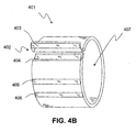
- FIG. 4A illustrates, in a side view, an arrangement of the cuff volume constraining device 401 where the longitudinal ends of the cuff volume constraining device 401 may be detachably attached at a detachable seam 402. This arrangement further includes two additional detachable attachment regions 405, 406.
- An arrangement of attachments/detachment device or means of detachable attachment may be a two-part hook and loop member, and other examples of detachable attachment include, but are not limited to: snaps, laces, and zippers.
- Additional exemplary detachable attachment regions or sites 405, 406 allow the volume and diameter of the cuff volume constraining device 401 to be adjusted to pre-determined diameters.
- the blood pressure cuff is typically inserted inside the cuff volume area 407 prior to expansion as part of a simulation.
- This arrangement may be made of nylon and made with a number of flexible, typically inelastic, materials and/or pieces of materials.
- FIG. 4B illustrates a perspective view of the arrangement of the cuff volume constraining 401 of FIG. 4A showing three detachable attachment sites or regions 404-406 that when brought into contact with the complementary region 403, may form one of three pre-set diameters, or looped longitudinal lengths, for volumetric cuff constraint.
- FIG. 5A is a top plan view of the arrangement of the cuff volume constraining device 401 of FIG. 4A , unrolled to illustrate the exemplary device having a first surface 501 that, when the cuff volume constraining device 401 is detachably attached at the seam 402, is the inward or cuff facing surface of the cuff volume constraining device 401.
- a first attachments/detachment device portion 403 such as the hook or loop portion of a hook and look device may be located at a first longitudinal end of the cuff volume constraining device 401.
- FIG. 5B is a bottom plan view of the arrangement of the cuff volume constraining device 401 of FIG.
- FIG. 5A unrolled to illustrate a second surface 502 that, when the cuff volume constraining device 401 is detachably attached at the seam 402, is the outward facing surface of the cuff volume constraining device 401.
- a second attachments/detachment device portion 404 such as the hook or loop portion of a hook and look device may be located at a second longitudinal end of the cuff volume constraining device 401. Additional detachable attachment sites 405, 406 are shown at intermediate points along on the exemplary cuff volume constraining device 401.
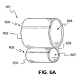
- FIG. 6A is a perspective view of an exemplary embodiment of the cuff volume constraining device 601 manufactured of a flexible inelastic material comprising a first hollow member 602 and a second hollow member 603, both being adapted in this example by way of their respective tubular apertures 606, 607 to receive a blood pressure cuff.
- the material may be fixedly attached to itself along one or more seams 604, 605 via, for example, stitches.
- This exemplary embodiment of the cuff volume constraining device 601 is thus able to constrain blood pressure cuffs across two ranges of volumes.
- a first chamber or cuff volume constraining aperture 606 may dimensioned to constrain a blood pressure cuff to approximately 100ml and the second cuff volume constraining aperture 607 may be dimensioned to constrain a blood pressure cuff to approximately 400 ml.
- This constraining device 601 is thus able to support the simulation and test for at least two volumetric ranges of cuff expansion, for example, to constrain the blood pressure cuff to a volume applicable or otherwise suitable for toddlers or small children 607, and the other cuff volume area suitable for adults 607.
- Other variations of the constraining device may also be created, such as a device having more than two hollow members 602, 603 each sized or adapted to constrain cuffs to differing pre-set volumes.
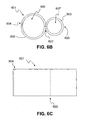
- FIG. 6B is a side view of an exemplary embodiment of the cuff volume constraining device showing a rounded fold 620 on one side of the device and a seam 604 opposite the side of the rounded fold 620 where an interposed stitch line 622 supports the second cuff volume constraining aperture 607 and where the interposed stitch 622 along with a stitched seam 604 support the first cuff volume constraining aperture 606.
- FIG. 6C is a top view of the exemplary embodiment of the cuff volume constraining device illustrating exemplary stitch lines 604, 622.
- FIG. 7A is a diagram of the cuff volume constraining device 101 as it may be deployed in testing a non-invasive blood pressure measurement device where the cuff volume constraining device 101 is positioned about the blood pressure cuff 701 which is pneumatically connected via a tube 702 to a blood pressure simulator 703 and a blood pressure monitor 704.
- the blood pressure cuff is inserted into the constraining device 101.
- the simulator 703 typically generates pressure signals that approximate those created by a patient's arm in surface contact with a blood pressure cuff where the pulses are measured by the blood pressure monitor 704 having its cuff volumetrically constrained by the exemplary cuff volume constraining device 101.
- FIG. 7A is a diagram of the cuff volume constraining device 101 as it may be deployed in testing a non-invasive blood pressure measurement device where the cuff volume constraining device 101 is positioned about the blood pressure cuff 701 which is pneumatically connected via a tube 702 to a blood pressure simulator 703 and a blood pressure
- FIG. 7B is a diagram of the cuff volume constraining device 601 as it may be used in testing a non-invasive blood pressure measurement device where a portion of the cuff volume constraining device 601 is positioned about the blood pressure cuff 701 which is pneumatically connected via a tube 702 to a blood pressure simulator 703 and a blood pressure monitor 704.
- the blood pressure cuff is inserted into one of the hollow members of differing diameters when expanded, i.e., in this exemplary embodiment either the first, or larger, hollow member 602 or the second, or smaller, hollow member 603, and in FIG. 7B is shown inserted into the second, or smaller, hollow member 603 of the cuff volume constraining device 601.
- the embodiments of the cuff volume constraining device shown in the various figures are for illustration purposes. Variations on the shape of the cuff volume constraining device may also be implemented, for example, having a constraining device that is hexagonal, octagonal, or any polygonal shape. This shape may be obtained before and/or even after the blood pressure cuff placed inside or inserted into the cuff volume area of the constraining device and inflated or expanded.
- the hollow member may be made in many ways, so that a cuff volume area is created thereby constraining the expansion of a blood pressure cuff.
- the cuff volume constraining device may be enclosed in one end, for example, forming a cup-like device wherein a blood pressure cuff may still be inserted into the open end or into the cuff volume area of the constraining device.
- Other flexible and inelastic materials may also be used.
Landscapes
- Health & Medical Sciences (AREA)
- Life Sciences & Earth Sciences (AREA)
- Cardiology (AREA)
- Vascular Medicine (AREA)
- Engineering & Computer Science (AREA)
- Medical Informatics (AREA)
- Physics & Mathematics (AREA)
- Ophthalmology & Optometry (AREA)
- Biophysics (AREA)
- Pathology (AREA)
- Dentistry (AREA)
- Biomedical Technology (AREA)
- Heart & Thoracic Surgery (AREA)
- Physiology (AREA)
- Molecular Biology (AREA)
- Surgery (AREA)
- Animal Behavior & Ethology (AREA)
- General Health & Medical Sciences (AREA)
- Public Health (AREA)
- Veterinary Medicine (AREA)
- Measuring Pulse, Heart Rate, Blood Pressure Or Blood Flow (AREA)
- Massaging Devices (AREA)
Claims (9)
- Système pour réaliser un essai sur un dispositif de mesure de tension artérielle non effractif, dans lequel le dispositif de mesure de tension artérielle comprend un dispositif de surveillance de tension artérielle et un manchon de prise de tension, le système comprenant un simulateur de tension artérielle adapté se raccorder de façon pneumatique au manchon de prise de tension et au dispositif de surveillance de tension artérielle ; et caractérisé en ce que le système comprend en outre :un élément creux et un second élément creux reliés l'un à l'autre, les deux étant adaptés pour recevoir et limiter de façon volumétrique le manchon de prise de tension.
- Système selon la revendication 1, dans lequel au moins un élément creux est tubulaire.
- Système selon la revendication 1, dans lequel au moins un élément creux est cylindrique.
- Système selon la revendication 1, dans lequel un premier élément creux limite le manchon de prise de tension à un volume inférieur à approximativement 400 ml et un second élément creux limite le manchon de prise de tension à un volume inférieur à approximativement 100 ml.
- Système selon la revendication 1, dans lequel au moins un élément creux est flexible et sensiblement non élastique.
- Système selon la revendication 1, dans lequel au moins un élément creux limite le diamètre et le volume maximums selon lesquels le manchon de prise de tension peut s'agrandir.
- Procédé pour réaliser un essai sur un dispositif de mesure de tension artérielle non effractif raccordé de façon pneumatique à un manchon de prise de tension, un simulateur de tension artérielle, et un dispositif de surveillance de tension artérielle, le procédé comprenant les étapes consistant à :placer le manchon de prise de tension dans une ouverture d'un élément de limite de volume de manchon dans lequel l'élément de limite de volume de manchon est adapté pour limiter le diamètre et le volume selon lesquels le manchon de prise de tension peut s'agrandir au cours de la réalisation de l'essai ; etélargir de façon pneumatique le manchon de prise de tension alors que le simulateur de tension artérielle simule un sujet d'essai, caractérisé en ce que l'élément de limite de volume de manchon comprend un premier élément creux et un second élément creux reliés l'un à l'autre.
- Procédé selon la revendication 7, dans lequel l'étape consistant à placer le manchon de prise de tension dans une ouverture de l'élément de limite de volume de manchon dans lequel l'élément de limite de volume de manchon est adapté pour limiter le diamètre et le volume selon lesquels le manchon de prise de tension peuvent s'élargir au cours de la réalisation de l'essai.
- Procédé selon la revendication 7, dans lequel l'étape consistant à placer le manchon de prise de tension dans une ouverture de l'élément de limite de volume de manchon comprend l'étape consistant à former l'ouverture sur le manchon de prise de tension par l'intermédiaire d'une couture détachable.
Applications Claiming Priority (3)
| Application Number | Priority Date | Filing Date | Title |
|---|---|---|---|
| US63335204P | 2004-12-03 | 2004-12-03 | |
| US11/164,652 US7226420B2 (en) | 2004-12-03 | 2005-11-30 | Cuff volume constraining device |
| PCT/US2005/043530 WO2006060606A2 (fr) | 2004-12-03 | 2005-12-01 | Dispositif de constriction de volume de manchon |
Publications (3)
| Publication Number | Publication Date |
|---|---|
| EP1816954A2 EP1816954A2 (fr) | 2007-08-15 |
| EP1816954A4 EP1816954A4 (fr) | 2009-07-29 |
| EP1816954B1 true EP1816954B1 (fr) | 2010-08-04 |
Family
ID=36565741
Family Applications (1)
| Application Number | Title | Priority Date | Filing Date |
|---|---|---|---|
| EP05852692A Expired - Lifetime EP1816954B1 (fr) | 2004-12-03 | 2005-12-01 | Dispositif de constriction de volume de manchon |
Country Status (5)
| Country | Link |
|---|---|
| US (1) | US7226420B2 (fr) |
| EP (1) | EP1816954B1 (fr) |
| AT (1) | ATE476139T1 (fr) |
| DE (1) | DE602005022754D1 (fr) |
| WO (1) | WO2006060606A2 (fr) |
Families Citing this family (13)
| Publication number | Priority date | Publication date | Assignee | Title |
|---|---|---|---|---|
| US7887330B2 (en) | 2004-12-02 | 2011-02-15 | The United States Of America As Represented By The Secretary Of The Army | Trauma training system |
| US20070292829A1 (en) * | 2004-12-02 | 2007-12-20 | King Lynn R | Intravenous (iv) training system |
| GB0722998D0 (en) * | 2007-11-23 | 2008-01-02 | Shturman Leonid | Blood pressure measuring cuff |
| US20100062407A1 (en) * | 2008-09-09 | 2010-03-11 | Paul Jacques Charles Lecat | Device And Methods For Medical Training Using Live Subjects |
| JP5206513B2 (ja) * | 2009-03-12 | 2013-06-12 | オムロンヘルスケア株式会社 | 機能追加モジュール |
| US20140182352A1 (en) * | 2012-12-27 | 2014-07-03 | General Electric Company | System and Method for Evaluating the Functionality of a Blood Pressure Cuff |
| CN103349545A (zh) * | 2013-05-21 | 2013-10-16 | 深圳市理邦精密仪器股份有限公司 | 一种模拟有创血压的装置及方法 |
| US20170238825A9 (en) * | 2013-06-25 | 2017-08-24 | Qardio, Inc. | Devices and methods for measuring blood pressure |
| US20160120445A1 (en) | 2014-11-05 | 2016-05-05 | Qardio, Inc. | Devices, systems and methods for contextualized recording of biometric measurements |
| US10360816B2 (en) | 2016-09-06 | 2019-07-23 | Dynasthetics, Llc | System and method for simulating fetal heart rate for noninvasive intra-partum fetal monitoring |
| US10269265B2 (en) | 2016-09-06 | 2019-04-23 | Dynasthetics, Llc | System and method for simulating intrauterine contractions for noninvasive intra-partum fetal monitoring |
| US10210774B2 (en) | 2016-11-17 | 2019-02-19 | Dynasthetics, Llc | System and method for simulating arterial pressure pulses |
| CN107865648A (zh) * | 2017-11-16 | 2018-04-03 | 广州视源电子科技股份有限公司 | 血压计测试方法、装置、移动终端及存储介质 |
Family Cites Families (14)
| Publication number | Priority date | Publication date | Assignee | Title |
|---|---|---|---|---|
| US3906937A (en) * | 1972-10-25 | 1975-09-23 | Para Medical Instr Corp | Blood pressure cuff and bladder and apparatus embodying the same |
| US3935984A (en) * | 1974-09-09 | 1976-02-03 | Ambitex Company | Automatic cuff mechanism for blood pressure measuring system |
| US4464123A (en) * | 1982-07-06 | 1984-08-07 | Critikon, Inc. | Arm simulator for an oscillometric blood pressure monitor |
| US4548249A (en) * | 1984-09-05 | 1985-10-22 | Slaughterbeck Perry K | Protective sleeve for sphygmomanometer cuff |
| US4716906A (en) | 1986-06-30 | 1988-01-05 | Spacelabs, Inc. | Blood pressure cuff |
| US5027641A (en) | 1989-02-23 | 1991-07-02 | Costello Jr Leo F | Oscillometric non-invasive blood pressure simulator |
| US5016466A (en) | 1989-10-27 | 1991-05-21 | Ness Dale C | Test apparatus and method for blood pressure measuring equipment |
| GB2280094A (en) * | 1993-07-20 | 1995-01-25 | Michael Gray | Belt for carrying an article, e.g. a pair of skis, on a person |
| DE4331451C1 (de) | 1993-09-16 | 1994-11-17 | Hewlett Packard Gmbh | Blutdruckmeßvorrichtung und Verfahren zum Steuern des Manschettendruckes bei einer Blutdruckmeßvorrichtung |
| US5535928A (en) * | 1995-03-13 | 1996-07-16 | Vel-Tye, L.L.C. | Belt-supportable carrier for portable articles |
| US5800359A (en) | 1995-05-19 | 1998-09-01 | Johnson & Johnson Medical, Inc. | NIBP playback system |
| JP3590462B2 (ja) * | 1995-09-20 | 2004-11-17 | コーリンメディカルテクノロジー株式会社 | 血圧測定装置 |
| US7401753B2 (en) | 2001-07-10 | 2008-07-22 | Harley-Davidson Motor Company Group, Inc. | Exhaust clamp for a motorcycle |
| US7021940B2 (en) | 2002-11-21 | 2006-04-04 | Northern Sydney Area Health Service | Patient simulator manikin and system |
-
2005
- 2005-11-30 US US11/164,652 patent/US7226420B2/en not_active Expired - Lifetime
- 2005-12-01 AT AT05852692T patent/ATE476139T1/de not_active IP Right Cessation
- 2005-12-01 DE DE602005022754T patent/DE602005022754D1/de not_active Expired - Lifetime
- 2005-12-01 EP EP05852692A patent/EP1816954B1/fr not_active Expired - Lifetime
- 2005-12-01 WO PCT/US2005/043530 patent/WO2006060606A2/fr not_active Ceased
Also Published As
| Publication number | Publication date |
|---|---|
| WO2006060606A3 (fr) | 2006-12-14 |
| EP1816954A4 (fr) | 2009-07-29 |
| US7226420B2 (en) | 2007-06-05 |
| DE602005022754D1 (de) | 2010-09-16 |
| US20060122518A1 (en) | 2006-06-08 |
| EP1816954A2 (fr) | 2007-08-15 |
| ATE476139T1 (de) | 2010-08-15 |
| WO2006060606A2 (fr) | 2006-06-08 |
Similar Documents
| Publication | Publication Date | Title |
|---|---|---|
| EP1816954B1 (fr) | Dispositif de constriction de volume de manchon | |
| RU2384293C1 (ru) | Манжета для монитора артериального давления и монитор артериального давления с упомянутой манжетой | |
| JP7069100B2 (ja) | 多機能手術用アクセスシステム | |
| US6988992B2 (en) | Blood pressure cuffs with resilient support sleeves | |
| US7166077B2 (en) | Cuff for measurement of blood pressure | |
| US6527727B2 (en) | Sphygmomanometer cuff capable of blocking blood flow favorably even with small width in wrapping direction | |
| US6308353B1 (en) | Method and apparatus for positioning a patient | |
| RU2013126600A (ru) | Развертывание эндолюминальных устройств | |
| US20080188360A1 (en) | Inflatable cushion bag for striking | |
| CN103872423B (zh) | 一种充气展开抛物柱面天线的卷曲折叠及充气展开结构 | |
| US20030125163A1 (en) | Springless bounce apparatus | |
| JP2005500939A (ja) | エアバッグ | |
| CN111795048A (zh) | 可充气结构 | |
| KR20060051284A (ko) | 혈압계용 커프 | |
| US20040058781A1 (en) | Springless bounce apparatus | |
| ES3054312T3 (en) | Constraining mechanisms for selective deployment and associated methods | |
| KR101089494B1 (ko) | 혈압계용 커프 및 그것을 구비한 혈압계 | |
| JP3100716U (ja) | ネットサポートの構造 | |
| JP5749600B2 (ja) | 血圧計用カフ | |
| CN213249346U (zh) | 一种腹腔镜鞘管防脱器 | |
| JP3747917B2 (ja) | 血圧計用カフ | |
| CN209884711U (zh) | 充气绑带、预适应训练绑带、血压计绑带和止血绑带 | |
| JP2010059628A (ja) | アーチ型気柱及び気柱テント | |
| CN220275266U (zh) | 一种气囊安装结构 | |
| CN221997827U (zh) | 血压测量装置 |
Legal Events
| Date | Code | Title | Description |
|---|---|---|---|
| PUAI | Public reference made under article 153(3) epc to a published international application that has entered the european phase |
Free format text: ORIGINAL CODE: 0009012 |
|
| 17P | Request for examination filed |
Effective date: 20070418 |
|
| AK | Designated contracting states |
Kind code of ref document: A2 Designated state(s): AT BE BG CH CY CZ DE DK EE ES FI FR GB GR HU IE IS IT LI LT LU LV MC NL PL PT RO SE SI SK TR |
|
| DAX | Request for extension of the european patent (deleted) | ||
| A4 | Supplementary search report drawn up and despatched |
Effective date: 20090630 |
|
| GRAP | Despatch of communication of intention to grant a patent |
Free format text: ORIGINAL CODE: EPIDOSNIGR1 |
|
| GRAS | Grant fee paid |
Free format text: ORIGINAL CODE: EPIDOSNIGR3 |
|
| GRAA | (expected) grant |
Free format text: ORIGINAL CODE: 0009210 |
|
| AK | Designated contracting states |
Kind code of ref document: B1 Designated state(s): AT BE BG CH CY CZ DE DK EE ES FI FR GB GR HU IE IS IT LI LT LU LV MC NL PL PT RO SE SI SK TR |
|
| REG | Reference to a national code |
Ref country code: GB Ref legal event code: FG4D |
|
| REG | Reference to a national code |
Ref country code: CH Ref legal event code: EP |
|
| REG | Reference to a national code |
Ref country code: IE Ref legal event code: FG4D |
|
| REF | Corresponds to: |
Ref document number: 602005022754 Country of ref document: DE Date of ref document: 20100916 Kind code of ref document: P |
|
| REG | Reference to a national code |
Ref country code: NL Ref legal event code: VDEP Effective date: 20100804 |
|
| LTIE | Lt: invalidation of european patent or patent extension |
Effective date: 20100804 |
|
| PG25 | Lapsed in a contracting state [announced via postgrant information from national office to epo] |
Ref country code: AT Free format text: LAPSE BECAUSE OF FAILURE TO SUBMIT A TRANSLATION OF THE DESCRIPTION OR TO PAY THE FEE WITHIN THE PRESCRIBED TIME-LIMIT Effective date: 20100804 Ref country code: FI Free format text: LAPSE BECAUSE OF FAILURE TO SUBMIT A TRANSLATION OF THE DESCRIPTION OR TO PAY THE FEE WITHIN THE PRESCRIBED TIME-LIMIT Effective date: 20100804 Ref country code: LT Free format text: LAPSE BECAUSE OF FAILURE TO SUBMIT A TRANSLATION OF THE DESCRIPTION OR TO PAY THE FEE WITHIN THE PRESCRIBED TIME-LIMIT Effective date: 20100804 Ref country code: NL Free format text: LAPSE BECAUSE OF FAILURE TO SUBMIT A TRANSLATION OF THE DESCRIPTION OR TO PAY THE FEE WITHIN THE PRESCRIBED TIME-LIMIT Effective date: 20100804 |
|
| PG25 | Lapsed in a contracting state [announced via postgrant information from national office to epo] |
Ref country code: PT Free format text: LAPSE BECAUSE OF FAILURE TO SUBMIT A TRANSLATION OF THE DESCRIPTION OR TO PAY THE FEE WITHIN THE PRESCRIBED TIME-LIMIT Effective date: 20101206 Ref country code: PL Free format text: LAPSE BECAUSE OF FAILURE TO SUBMIT A TRANSLATION OF THE DESCRIPTION OR TO PAY THE FEE WITHIN THE PRESCRIBED TIME-LIMIT Effective date: 20100804 Ref country code: IS Free format text: LAPSE BECAUSE OF FAILURE TO SUBMIT A TRANSLATION OF THE DESCRIPTION OR TO PAY THE FEE WITHIN THE PRESCRIBED TIME-LIMIT Effective date: 20101204 Ref country code: CY Free format text: LAPSE BECAUSE OF FAILURE TO SUBMIT A TRANSLATION OF THE DESCRIPTION OR TO PAY THE FEE WITHIN THE PRESCRIBED TIME-LIMIT Effective date: 20100804 Ref country code: BG Free format text: LAPSE BECAUSE OF FAILURE TO SUBMIT A TRANSLATION OF THE DESCRIPTION OR TO PAY THE FEE WITHIN THE PRESCRIBED TIME-LIMIT Effective date: 20101104 Ref country code: SI Free format text: LAPSE BECAUSE OF FAILURE TO SUBMIT A TRANSLATION OF THE DESCRIPTION OR TO PAY THE FEE WITHIN THE PRESCRIBED TIME-LIMIT Effective date: 20100804 |
|
| PG25 | Lapsed in a contracting state [announced via postgrant information from national office to epo] |
Ref country code: GR Free format text: LAPSE BECAUSE OF FAILURE TO SUBMIT A TRANSLATION OF THE DESCRIPTION OR TO PAY THE FEE WITHIN THE PRESCRIBED TIME-LIMIT Effective date: 20101105 Ref country code: BE Free format text: LAPSE BECAUSE OF FAILURE TO SUBMIT A TRANSLATION OF THE DESCRIPTION OR TO PAY THE FEE WITHIN THE PRESCRIBED TIME-LIMIT Effective date: 20100804 Ref country code: LV Free format text: LAPSE BECAUSE OF FAILURE TO SUBMIT A TRANSLATION OF THE DESCRIPTION OR TO PAY THE FEE WITHIN THE PRESCRIBED TIME-LIMIT Effective date: 20100804 Ref country code: SE Free format text: LAPSE BECAUSE OF FAILURE TO SUBMIT A TRANSLATION OF THE DESCRIPTION OR TO PAY THE FEE WITHIN THE PRESCRIBED TIME-LIMIT Effective date: 20100804 |
|
| PG25 | Lapsed in a contracting state [announced via postgrant information from national office to epo] |
Ref country code: DK Free format text: LAPSE BECAUSE OF FAILURE TO SUBMIT A TRANSLATION OF THE DESCRIPTION OR TO PAY THE FEE WITHIN THE PRESCRIBED TIME-LIMIT Effective date: 20100804 |
|
| PG25 | Lapsed in a contracting state [announced via postgrant information from national office to epo] |
Ref country code: SK Free format text: LAPSE BECAUSE OF FAILURE TO SUBMIT A TRANSLATION OF THE DESCRIPTION OR TO PAY THE FEE WITHIN THE PRESCRIBED TIME-LIMIT Effective date: 20100804 Ref country code: IT Free format text: LAPSE BECAUSE OF FAILURE TO SUBMIT A TRANSLATION OF THE DESCRIPTION OR TO PAY THE FEE WITHIN THE PRESCRIBED TIME-LIMIT Effective date: 20100804 Ref country code: EE Free format text: LAPSE BECAUSE OF FAILURE TO SUBMIT A TRANSLATION OF THE DESCRIPTION OR TO PAY THE FEE WITHIN THE PRESCRIBED TIME-LIMIT Effective date: 20100804 Ref country code: RO Free format text: LAPSE BECAUSE OF FAILURE TO SUBMIT A TRANSLATION OF THE DESCRIPTION OR TO PAY THE FEE WITHIN THE PRESCRIBED TIME-LIMIT Effective date: 20100804 Ref country code: CZ Free format text: LAPSE BECAUSE OF FAILURE TO SUBMIT A TRANSLATION OF THE DESCRIPTION OR TO PAY THE FEE WITHIN THE PRESCRIBED TIME-LIMIT Effective date: 20100804 |
|
| PLBE | No opposition filed within time limit |
Free format text: ORIGINAL CODE: 0009261 |
|
| STAA | Information on the status of an ep patent application or granted ep patent |
Free format text: STATUS: NO OPPOSITION FILED WITHIN TIME LIMIT |
|
| PG25 | Lapsed in a contracting state [announced via postgrant information from national office to epo] |
Ref country code: ES Free format text: LAPSE BECAUSE OF FAILURE TO SUBMIT A TRANSLATION OF THE DESCRIPTION OR TO PAY THE FEE WITHIN THE PRESCRIBED TIME-LIMIT Effective date: 20101115 |
|
| 26N | No opposition filed |
Effective date: 20110506 |
|
| PG25 | Lapsed in a contracting state [announced via postgrant information from national office to epo] |
Ref country code: MC Free format text: LAPSE BECAUSE OF NON-PAYMENT OF DUE FEES Effective date: 20101231 |
|
| REG | Reference to a national code |
Ref country code: CH Ref legal event code: PL |
|
| REG | Reference to a national code |
Ref country code: DE Ref legal event code: R097 Ref document number: 602005022754 Country of ref document: DE Effective date: 20110506 |
|
| REG | Reference to a national code |
Ref country code: FR Ref legal event code: ST Effective date: 20110831 |
|
| PG25 | Lapsed in a contracting state [announced via postgrant information from national office to epo] |
Ref country code: CH Free format text: LAPSE BECAUSE OF NON-PAYMENT OF DUE FEES Effective date: 20101231 Ref country code: IE Free format text: LAPSE BECAUSE OF NON-PAYMENT OF DUE FEES Effective date: 20101201 Ref country code: LI Free format text: LAPSE BECAUSE OF NON-PAYMENT OF DUE FEES Effective date: 20101231 Ref country code: FR Free format text: LAPSE BECAUSE OF NON-PAYMENT OF DUE FEES Effective date: 20110103 |
|
| PG25 | Lapsed in a contracting state [announced via postgrant information from national office to epo] |
Ref country code: LU Free format text: LAPSE BECAUSE OF NON-PAYMENT OF DUE FEES Effective date: 20101201 Ref country code: HU Free format text: LAPSE BECAUSE OF FAILURE TO SUBMIT A TRANSLATION OF THE DESCRIPTION OR TO PAY THE FEE WITHIN THE PRESCRIBED TIME-LIMIT Effective date: 20110205 |
|
| PG25 | Lapsed in a contracting state [announced via postgrant information from national office to epo] |
Ref country code: TR Free format text: LAPSE BECAUSE OF FAILURE TO SUBMIT A TRANSLATION OF THE DESCRIPTION OR TO PAY THE FEE WITHIN THE PRESCRIBED TIME-LIMIT Effective date: 20100804 |
|
| REG | Reference to a national code |
Ref country code: DE Ref legal event code: R082 Ref document number: 602005022754 Country of ref document: DE |
|
| PGFP | Annual fee paid to national office [announced via postgrant information from national office to epo] |
Ref country code: DE Payment date: 20191119 Year of fee payment: 15 |
|
| REG | Reference to a national code |
Ref country code: DE Ref legal event code: R119 Ref document number: 602005022754 Country of ref document: DE |
|
| PG25 | Lapsed in a contracting state [announced via postgrant information from national office to epo] |
Ref country code: DE Free format text: LAPSE BECAUSE OF NON-PAYMENT OF DUE FEES Effective date: 20210701 |
|
| PGFP | Annual fee paid to national office [announced via postgrant information from national office to epo] |
Ref country code: GB Payment date: 20231218 Year of fee payment: 19 |
|
| GBPC | Gb: european patent ceased through non-payment of renewal fee |
Effective date: 20241201 |
|
| PG25 | Lapsed in a contracting state [announced via postgrant information from national office to epo] |
Ref country code: GB Free format text: LAPSE BECAUSE OF NON-PAYMENT OF DUE FEES Effective date: 20241201 |