EP1816976B1 - Mise en place d'objets orthodontiques le long d'un arc dentaire dans un environnement tridimensionnel (3d) - Google Patents
Mise en place d'objets orthodontiques le long d'un arc dentaire dans un environnement tridimensionnel (3d) Download PDFInfo
- Publication number
- EP1816976B1 EP1816976B1 EP05793948.0A EP05793948A EP1816976B1 EP 1816976 B1 EP1816976 B1 EP 1816976B1 EP 05793948 A EP05793948 A EP 05793948A EP 1816976 B1 EP1816976 B1 EP 1816976B1
- Authority
- EP
- European Patent Office
- Prior art keywords
- tooth
- orthodontic
- archwire
- teeth
- intersect
- Prior art date
- Legal status (The legal status is an assumption and is not a legal conclusion. Google has not performed a legal analysis and makes no representation as to the accuracy of the status listed.)
- Expired - Lifetime
Links
Images


Classifications
-
- A—HUMAN NECESSITIES
- A61—MEDICAL OR VETERINARY SCIENCE; HYGIENE
- A61C—DENTISTRY; APPARATUS OR METHODS FOR ORAL OR DENTAL HYGIENE
- A61C7/00—Orthodontics, i.e. obtaining or maintaining the desired position of teeth, e.g. by straightening, evening, regulating, separating, or by correcting malocclusions
- A61C7/002—Orthodontic computer assisted systems
Definitions
- the invention relates to electronic orthodontics and, more particularly, computer-based techniques for assisting orthodontic diagnosis and treatment.
- the field of orthodontics is concerned with repositioning and aligning a patient's teeth for improved occlusion and aesthetic appearance.
- orthodontic treatment often involves the use of tiny slotted appliances, known as brackets that are fixed to the patient's anterior, cuspid, and bicuspid teeth.
- An archwire is received in the slot of each bracket and serves as a track to guide movement of the teeth to desired orientations.
- the ends of the archwire are usually received in appliances known as buccal tubes that are secured to the patient's molar teeth.
- a number of orthodontic appliances in commercial use today are constructed on the principle of the "straight wire concept" developed by Dr. Lawrence F. Andrews, D.D.S.
- the shape of the appliances including the orientation of the slots of the appliances, is selected so that the slots are aligned in a flat reference plane at the conclusion of treatment.
- a resilient archwire is selected with an overall curved shape that normally lies in a flat reference plane.
- the archwire When the archwire is placed in the slots of the straight wire appliances at the beginning of orthodontic treatment, the archwire is often deflected upwardly or downwardly from one appliance to the next in accordance with the patient's malocclusions.
- the resiliency of the archwire tends to return the archwire to its normally curved shape that lies in a flat reference plane.
- the attached teeth are moved in a corresponding fashion toward an aligned, aesthetically pleasing array.
- each bracket it is important for the practitioner using straight wire appliances to fix each bracket in the exact proper position on the corresponding tooth. If, for example, a bracket is placed too far in an occlusal direction on the tooth surface, the archwire will tend to position the crown of the tooth too close to the gingiva (gums) at the end of the treatment. As another example, if the bracket is placed to one side of the center of the tooth in either the mesial or distal direction, the resultant tooth orientation will likely be an orientation that is excessively rotated about its long axis.
- bracket positions by the use of a ruler, protractor and pencil to measure and mark features on a plaster cast made from impressions of the patient's teeth. This process is often difficult to carry out with precision, and may be subjective in nature. Consequently, it is often difficult for the practitioner to ensure that the brackets are precisely positioned on the teeth at correct locations.
- US 2004/0142298 discloses a method for virtual orthodontic treatment comprising moving teeth horizontally by sliding along the archwire, to avoid collision between the teeth.
- US 2002/0150859 discloses a virtual orthodontic method comprising collision or contact detection features and also the feature that when one virtual tooth is moved to a new location, the tooth is automatically moved into close proximity or touching contact with the adjacent or opposite tooth.
- US 2003/0163291 discloses a method of orthodontic appliance selection providing multimedia representations such as sound to represent collision between teeth.
- US 2002/0015934 discloses interactive orthodontic care system based on intra-oral scanning teeth comprising collision detection algorithms, wherein when the collisions are detected, the user can be notified of the collision and resolve the conflict between teeth , for example by selecting one tooth as a primary tooth and moving that tooth first in an initial stage of treatment, and then moving the other tooth in a secondary stage of treatment.
- US 2002/064746 discloses a method to prepare a malocclusion treatment plan comprising a collision detection program to determine whether collisions will occur along the chosen paths. If collisions or an unacceptable bite will occur, the program iteratively alters the offending tooth path until all conditions are met.
- the system automatically determines positions of orthodontic objects (such as teeth and/or orthodontic appliances) along an archwire within a three-dimensional (3D) environment based on a proposed orthodontic prescription.
- An orthodontic practitioner may interact with the system to enter a proposed orthodontic prescription, or the system may choose the proposed orthodontic prescription from a number of standardized prescriptions stored in a database.
- the system may also display a digital representation of the teeth at the determined positions.
- the invention is directed to a method as defined in claim 1 comprising automatically determining positions of orthodontic objects along an archwire within a three-dimensional (3D) environment based on a proposed orthodontic prescription, and displaying a digital representation of the orthodontic objects at the determined positions.
- the invention is also directed to a system as defined in claim 14, comprising a computing device and modeling software executing on the computing device to provide a three-dimensional (3D) environment.
- the modeling software comprises a tooth packing control module that automatically determines positions of orthodontic objects along an archwire within a three-dimensional (3D) environment based on a proposed orthodontic prescription, and a user interface that displays a digital representation of the orthodontic objects at the determined positions.
- the present disclosure also describes a computer-readable medium containing instructions.
- the instructions cause a programmable processor to automatically determine positions of orthodontic objects along an archwire within a three-dimensional (3D) environment based on a proposed orthodontic prescription, and display a digital representation of the orthodontic objects at the determined positions.
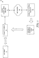
- FIG. 1 is a block diagram illustrating an exemplary computer environment 2 in which a client computing device 4 presents an environment for automatically determining positions of orthodontic objects, such as teeth and/or orthodontic appliances, along an archwire based on a proposed orthodontic prescription.
- the client computing device may also generate a three-dimensional (3D) representation of the orthodontic objects at the determined positions.
- Orthodontic practitioner 8 may interact with the system to enter a proposed orthodontic prescription, or, client computing device 4 may choose a proposed prescription from a number of standardized prescriptions stored in a database. The system thus allows the practitioner to visualize the final occlusion resulting from the proposed orthodontic prescription at the conclusion of treatment.
- Visualization of the teeth at the determined positions enables the practitioner to determine whether the proposed orthodontic prescription will achieve an acceptable functional and/or aesthetic result.
- the practitioner may decide, based on the displayed final occlusion, to change or modify the proposed orthodontic prescription for certain ones or for all of the orthodontic objects to achieve a desired functional or aesthetic result.
- the practitioner may modify the proposed prescription and view the orthodontic objects at the associated determined positions until an acceptable result is achieved.
- the terms "orthodontic prescription” or “prescription” refer to the geometric attributes inherent in the selected orthodontic appliances and to relative positions and orientations of each appliance with respect to its associated tooth.
- Practitioner 8 may interact with the modeling software to view the 3D digital representation of the teeth and to define a proposed orthodontic prescription.
- Practitioner 8 may define the proposed orthodontic prescription by selecting virtual brackets that embody certain geometric attributes and precisely positioning those virtual brackets on individual teeth within the modeled dental arch. During this process, the modeling software manipulates each bracket as a separate object within the 3D environment, and fixes the position of each bracket within the 3D space relative to a coordinate system associated with the bracket's associated tooth. Consequently, practitioner 8 is able to independently view and precisely locate each bracket within the 3D environment relative to its respective tooth.
- client computing device determines positions of the teeth based on the proposed prescription and the practitioner has indicated his or her approval
- client computing device 4 communicates the bracket placement positions to manufacturing facility 12 via network 14.
- manufacturing facility constructs an indirect bonding tray 16 for use in physically placing brackets on the teeth of patient 6.
- manufacturing facility 12 fabricates indirect bonding tray 16 based on the bracket placement positions selected by practitioner 8 within the 3D environment presented by client computing device 4.
- Manufacturing facility 12 may, for example, use conventional commercially available brackets selected by practitioner 8 to form indirect bonding tray 16.
- Manufacturing facility 12 forwards indirect bonding tray 16 to practitioner 8 for use in a conventional indirect bonding procedure to place the brackets on the teeth of patient 6.
- client computing device 4 need not forward the bracket placement positions to manufacturing facility 12.
- Client computing device 4 may instead output, e.g., display or print, the relevant distances and angles for each bracket to assist practitioner 8 in manually positioning the brackets on the teeth of patient 6.
- client computing device 4 may display and/or position any type of orthodontic appliance without departing from the scope of the present invention.
- orthodontic appliances include orthodontic brackets, buccal tubes, sheaths or buttons.
- client computing device 4 need not display a full visual representation of the appliance. Rather, a portion of the appliance may be displayed.
- client computing device 4 need not display the appliance itself. Rather, another object associated with an appliance or with the placement of an appliance may be shown instead of or in addition to the appliance itself.
- appliance or “bracket” as used herein shall therefore be understood to include any type of appliance, a full or partial representation of an appliance, or any object associated with an appliance and/or its placement.
- Client computing device 4 may show a digital representation of an entire dental arch, a portion of a dental arch, an individual tooth within the dental arch, or a portion of a tooth within the dental arch, or some combination thereof for viewing by the practitioner. Client computing device 4 may also show a digital representation of appliances on all of the teeth in a dental arch, the appliances on a portion of the teeth in a dental arch, an appliance on a single tooth, or an appliance on a portion of a tooth. Similarly, client computing device 4 may show a digital representation of an entire appliance, a portion of an appliance, or simply the crosshairs of an appliance (which may indicate, for example, the location on a tooth where the center of the appliance is to be placed). It shall be understood, therefore, that the image presented to the practitioner 8 by client computing device 4 may take many different forms, and that the invention is not limited in this respect.
- the 3D representation of the dental arch may be initially generated by digitally scanning a physical dental impression of the teeth of patient 6 or by scanning a casting made from the impression.
- practitioner 8 may use an intraoral scanner to produce the 3D digital representation directly from the teeth of patient 6. Other methods of scanning may also be used.
- FIG. 2 is a block diagram illustrating an example embodiment of client computing device 4 in further detail.
- client computing device 4 provides an operating environment for modeling software 20.
- modeling software 20 presents a modeling environment for modeling and depicting the 3D representation of the teeth of patient 6 ( FIG. 1 ).
- modeling software 20 includes a user interface 22, a tooth packing control module 24 and a rendering engine 26.
- User interface 22 provides a graphical user interface (GUI) that visually displays the 3D representation of the patient's teeth as well as 3D representations of the brackets.
- GUI graphical user interface
- user interface 22 provides an interface for receiving input from practitioner 8, e.g., via a keyboard and a pointing device, for manipulating the brackets and placing the brackets on respective teeth within the modeled dental arch.
- User interface 22 also visually displays a 3D representation of the final occlusion generated by tooth packing control module 24.
- Modeling software 20 interacts with database 30 to access a variety of data, such as bracket data 32, 3D data 34, patient data 36, and placement rules 40.
- Database 30 may be represented in a variety of forms including data storage files, lookup tables, or a database management system (DBMS) executing on one or more database servers.
- the database management system may be a relational (RDBMS), hierarchical (HDBMS), multidimensional (MDBMS), object oriented (ODBMS or OODBMS), object relational (ORDBMS) or other type of database management system.
- the data may, for example, be stored within a single relational database such as SQL Server from Microsoft Corporation.
- database 30 may be located remote from the client computing device and coupled to the client computing device via a public or private network, e.g., network 14.
- Bracket data 32 describes a set of commercially available brackets that may be selected by practitioner 8 and positioned within the 3D modeling environment.
- bracket data 32 may store a variety of attributes for the commercially available brackets, such as dimensions, slot locations and characteristics, torque angles, angulations and other attributes.
- User interface 22 provides a menu-driven interface by which practitioner 8 selects the type of brackets for use in defining an orthodontic prescription for patient 6.
- Patient data 36 describes a set of one or more patients, e.g., patient 6, associated with practitioner 8.
- patient data 36 specifies general information, such as a name, birth date, and a dental history, for each patient.
- patient data 36 specifies a current prescription specified for each of the patients, including the types of brackets selected by practitioner 8 for use with each of the patients, and their associated positions and orientations on the teeth of patient 6.
- the orthodontic industry has developed standard prescriptions for many commercially available orthodontic brackets. These standardized prescriptions generally tend to satisfy the functional and the aesthetic requirements for most patients. The standardized prescriptions may be used to achieve uniformity among patients or to avoid the more time consuming process of devising a custom set of metrics for each individual patient.
- a standardized set of metrics for the teeth in the dentition may be satisfactory.
- practitioner 8 may desire to create a customized prescription to achieve a more aesthetically pleasing result, or to more adequately take into account that patient's malocclusions.
- a combination of standardized and customized prescriptions for different teeth in the dentition may be used. Practitioner 8 inputs the desired prescription via user interface 22, which is then stored in database 30 as patient data 36.
- Placement rules 40 may specify industry-defined placement rules for commercially available brackets.
- placement rules 40 may include user-defined rules specified by practitioner 8 or other rules for controlling bracket placement.
- one rule for certain commercially available brackets is to align the medial line or longitudinal axis of the bracket with the Facial Axis of the Clinical Crown (FACC) of the tooth.
- the FACC is defined as the curved line formed by the intersection of the mid-sagittal plane and the facial surface of the tooth.
- Another exemplary industry-defined placement rule is to place the center of a base of the bracket on the FACC of the tooth equidistant from the occlusal edge or occlusal-most point on the FACC and the gingival margin of the crown.
- This location is also known as the Facial Axis Point (FA Point).
- FA Point Facial Axis Point
- practitioner 8 may desire to place brackets at a position that is different from the FA Point. Consequently, practitioner 8 may specify different prescriptions for different types of teeth in the dentition, for different types of brackets, or both.
- the prescription may be based in whole or in part on known rules associated with a particular type of the appliances selected by practitioner 8.
- Rendering engine 26 accesses and renders 3D data 34 to generate the 3D view presented to practitioner 8 by user interface 22. More specifically, 3D data 34 includes information defining the 3D objects that represent each tooth and bracket within the 3D environment. Rendering engine 26 processes each object to render a 3D triangular mesh based on viewing perspective of practitioner 8 within the 3D environment. User interface 22 displays the rendered 3D triangular mesh to practitioner 8, and allows the practitioner to change viewing perspectives and manipulate objects within the 3D environment.
- Tooth packing control module 24 receives a proposed prescription from patient data 36 and automatically places teeth along an archwire based on the proposed prescription.
- the digital representation of the resulting final occlusion may be displayed on user interface 22.
- Practitioner 8 may then view the visual representation of the final occlusion to determine whether the proposed prescription will give a desired functional and/or aesthetic result or whether the proposed prescription should be modified.
- Orthodontic appliances may initially be placed in the 3D environment using any of several different methods.
- the brackets may initially be placed in the 3D environment using the method described in copending and commonly assigned U.S. Patent Application Publication Number US 2005/0130095 -A1 , entitled “Method of Placing Orthodontic Brackets on Teeth in a 3D Virtual World", published June 16, 2005to Raby, et al..
- Manual adjustment of orthodontic brackets may be assisted by use of visual planar guides, as described in US 2005/0170309 , entitled “Planar Guides to Visually Aid Orthodontic Appliance Placement within a Three-Dimensional (3D) Environment", filed February 4, 2004 to Raby, et al..
- a system visually aids the user in manual placement of brackets through manual adjustments to bracket position and orientation.
- Other methods of placing or adjusting the position of brackets on the teeth may also be used.
- tooth packing control module 24 "packs" (in other words, places or positions) the teeth along a virtual archwire.
- tooth packing control module 24 automatically determines the positions of the teeth along the archwire so that adjacent teeth do not overlap and are no more than a defined distance apart.
- tooth packing control module 24 Once tooth packing control module 24 has determined the tooth positions, rendering engine 26 generates a representation of the relative position and orientation of each virtual bracket with respect to the virtual arch at the conclusion of treatment. In one embodiment, tooth packing control module 24 automatically determines the positions of teeth along the archwire based on the proposed prescription using the straight-wire concept. However, it shall be understood that methods other than the straight wire concept could also be used, and that the invention is not limited in this respect.
- the virtual representation of the teeth at the determined positions approximates the actual relative positions and orientations of the patient's teeth at the conclusion of treatment.
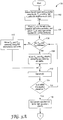
- FIGS. 3A and 3B are a flowchart 100 illustrating a method of automatically determining positions of teeth along an archwire based on a proposed orthodontic prescription. More specifically, the flowchart of FIGS. 3A and 3B illustrates operation of modeling software 20 in automatically determining positions of teeth along a virtual archwire to generate a digital representation of a final occlusion within the 3D virtual environment based on the proposed orthodontic prescription.
- tooth packing control module 24 first identifies the anterior-most tooth in each of the right and left quadrants, T R0 and T L0 , (102). Initially, tooth packing control module 24 places each tooth along the archwire a defined distance d from the median of the archwire (104). Tooth packing control module 24 places a tooth along the archwire, orienting the tooth such that the archwire passes through the slot of the bracket on that tooth. Tooth packing control module 24 next determines whether the two teeth intersect (106). One exemplary method by which tooth packing control module 24 may determine whether two teeth intersect is described below with respect to FIGS. 12A and 12B .
- tooth packing control module 24 moves each tooth away (distally) from the median line of the arch wire by d/2 units (108). If they do not intersect, tooth packing control module 24 moves each tooth toward (mesially) the median line by d/2 units (110). The distance d is set to d/2 for the next iteration (112). Each iteration, tooth packing control module 24 moves both teeth either toward the median line of the archwire if they do not intersect or moves them away from the median line of the archwire if they do intersect. Tooth packing control module 24 continues this process, setting the distance d to one half of its previous value (112) each iteration, until the distance d is within a desired tolerance t (114).
- the tolerance t may be a defined value or may be a defined number of iterations.
- tooth packing control module 24 places the remaining teeth in that arch.
- tooth packing control module 24 places the teeth along the archwire one quadrant at a time. For example, tooth packing control module 24 may begin with the right quadrant (116). Tooth packing control module 24 may then place the second anterior-most tooth of that quadrant (T Qi ) distance d along the archwire distally from the final position of the anterior-most tooth (T Qi-1 ) of that quadrant (120) as determined in the previous step.
- An index i denotes the selected tooth in the current quadrant (denoted by Q) and ranges from 0 to 1 less than the number of teeth within the quadrant.
- tooth packing control module 24 determines whether the anterior-most tooth and the second anterior-most tooth intersect (122).
- tooth packing control module 24 moves the second anterior-most tooth away from the anterior-most tooth by one half the starting distance, d/2 (124). If they do not intersect, tooth packing control module 24 moves the second anterior-most tooth toward the anterior-most tooth by half the starting distance, d/2 (126). In preparation for the next iteration, tooth packing control module 24 sets the distance d to d/2 (128).
- Tooth packing control module 24 continues in this manner until the second anterior-most tooth is placed within a desired tolerance t (130). Tooth packing control module 24 checks the value of index i to determine whether the distal-most tooth in that quadrant has been placed (132). If not, tooth packing control module 24 repeats this process, iteratively placing each of the remaining teeth in the right quadrant, each iteration placing the next remaining anterior-most tooth in that quadrant. Tooth packing control module 24 then checks whether the teeth in both quadrants have been placed by determining whether it has placed teeth in the last remaining quadrant (134). If not, tooth packing control module 24 then repeats the entire process with the remaining quadrant (the left quadrant, in this example) (136). After tooth packing control module 24 places all of the teeth in the left quadrant (134), adjacent teeth along the entire arch are positioned along the archwire, without intersecting, within some specified and predetermined tolerance t.
- FIGS. 4-8 illustrate determining positions of the teeth along an archwire according to the method described above.
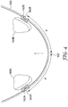
- FIG. 4 shows the two anterior-most teeth 160A and 160B each placed distance d from the midline 152 of archwire 150. The distance d may be measured from any appropriate point on the tooth, such as the midpoint of an appliance associated with the tooth, e.g., the bracket.
- Each tooth 160A and 160B is oriented such that archwire 150 passes through each of the respective slots 164A and 164B of brackets 162A and 162B.
- Tooth packing control module 24 performs an intersection check and determines that teeth 160A and 160B do not in intersect.
- Tooth packing control module 24 then moves each tooth 160A and 160B a distance of d/2 mesially along archwire 150 (i.e., toward archwire midline 152).
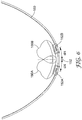
- FIG. 5 shows anterior-most teeth 160A and 160B after tooth packing control module 24 moves them both a distance of d/2 mesially toward the midline 152 of archwire 150.
- Tooth packing control module 24 next performs an intersection check at this new position and determines that, in this example, teeth 160A and 160B do not intersect. Therefore, tooth packing control module 24 moves each tooth 160A and 160B a distance of d/4 mesially along archwire 150 (i.e., toward archwire midline 152).
- FIG. 6 shows anterior-most teeth 160A and 160B after another iteration, i.e., after tooth packing control module 24 moves both teeth 160A and 160B a distance of d/4 toward the midline 152 from their previous position shown in FIG. 5 .
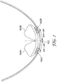
- Tooth packing control module 24 performs an intersection check at this new position shown in FIG. 6 and determines that the teeth are in intersection. Consequently, tooth packing control module 24 moves each tooth 160A and 160B a distance of d/8 distally along archwire 150 away from midline 152 as shown in FIG. 7 . After this movement, the teeth 160A and 160B in FIG. 7 no longer intersect.
- Tooth packing control module 24 continues this process until all of the teeth in the current quadrant are placed within some desired predetermined tolerance t. After each movement j, t is equal to d/2 j , and this tolerance represents the maximum distance that each tooth lies from its ideal position (defined as touching the adjacent tooth at one point of contact).
- tooth packing control module 24 may place the second-most anterior tooth in the right quadrant along archwire 150.
- FIG. 8 shows second-most anterior tooth 170A whose bracket 172A is placed a distance d from the bracket 162A of anterior-most tooth 160A. Tooth packing control module 24 repeats this process for the second-most anterior tooth 170A in the right quadrant until that tooth is within the desired tolerance t of the anterior-most tooth. Tooth packing control module 24 repeats this entire process until all teeth in the right quadrant have been placed, and then again until all teeth in the left quadrant have been placed. The same types of movements shown above are performed for the subsequent teeth, except that any teeth already placed do not move.
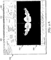
- FIGS. 9A and 9B are display diagrams illustrating an exemplary graphical user interface (GUI) presented by modeling software 20.
- GUI graphical user interface
- FIGS. 9A and 9B illustrate an exemplary user interface 300 that depicts the teeth in accordance with the positions determined by tooth packing control module 24.
- user interface 300 includes a menu input area 302 by which a user, e.g., practitioner 8, accesses a proposed electronic prescription for patient 6.
- User interface 300 further includes display area 304 for presenting the 3D rendered representation of the teeth of patient 6.
- display area 304 presents a virtualized facial view 308 of the dental arch of patient 6 resulting from a proposed orthodontic prescription.
- display area 304 presents a virtualized bottom view 310 of the dental arch of patient 6 with the teeth in the positions determined by tooth packing control module 24 based on the proposed orthodontic prescription.
- User interface 300 provides selection mechanism 306 by which practitioner 8 can selectively enable and disable the rendering and display of any of several different views of the patient's dental arch within the display area 302.
- the 3D rendered representations 308 and 310 of the final occlusion allow practitioner 8 to determine whether the proposed prescription will satisfactorily achieve functional occlusion and meet the practitioner's and/or the patient's aesthetic requirements.
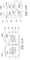
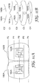
- FIGS. 10A, 10B , 11A and 11B illustrate a simplified example of a method that modeling software 20 may utilize to determine whether two teeth intersect.
- the method makes use of the fact that each tooth includes a bracket whose slot fits around the archwire, a planar object.
- modeling software 20 stores a 3D Affine transform in database 30. This transform includes details about the position and orientation of each bracket in relation to its associated tooth.
- Modeling software 20 may also generate another 3D Affine transform that transforms the original bracket coordinate system to a coordinate system lying in the slot of the bracket and oriented in such a way that the modeling software may extract information about the plane of the bracket's archwire slot.
- modeling software 20 may define the plane of the archwire in relation to the tooth. This plane intersects the tooth, and the intersection creates a cross-section of the tooth, more specifically a polyline that outlines the cross-section. Multiple tooth cross-sections can be created by considering new planes that lie parallel to the original plane of the archwire and are translated above or below the original plane by some given distance, constrained by the extent of the tooth in those directions.
- FIG. 10A is an exemplary facial diagram of two anterior-most teeth 160A and 160B and their associated brackets 162A and 162B, respectively.
- Plane P0 is the plane that lies in the plane of the archwire.
- Planes P1 and P2 are parallel to plane P0 and lie above plane P0.
- Planes P3 and P4 are parallel to plane P0 and lie below plane P0.
- FIG. 10A there are two planes drawn above and below the archwire plane.
- FIG. 10B shows cross-sections C0, C1, C2, C3 and C4 formed by intersections of the corresponding planes P0, P1, P2, P3 and P4, respectively with the teeth 160A and 160B.
- tooth packing control module 24 would determine that teeth 160A and 160B do not intersect.
- FIG. 11A is a facial diagram of two anterior-most teeth 160A and 160B, their associated brackets 162A and 162B, respectively, and planes PO-P4.
- FIG. 11B shows corresponding cross-sections C0-C4.
- tooth packing control module 24 would detect intersection in three of the cross-sections (C0, C3, and C4). In this case, tooth packing control module 24 would therefore determine that teeth 160A and 160B in FIGS. 11A and 11B are in intersection.
- tooth packing control module 24 may make use of fewer or many more planes to gather more cross-section and/or polyline information. Use of more cross-sections may increase the accuracy of intersection detection. In one embodiment, at least 50 cross-sections may be used. In another embodiment, at least 100 cross-sections may be used.
- one parameter which may be adjusted is the number of planes that are used, thus determining how many cross-sections for each tooth are considered.
- the accuracy of the algorithm may be improved.
- the execution speed of the algorithm may be improved. It shall be understood that although specific examples are given herein, the precise number of planes and cross-sections used may be varied to achieve the desired levels of speed and accuracy, and that the invention is not limited in this respect.
- Tooth packing control module 24 determines the set of planes used to find cross-sections in each of the two teeth that are being tested for intersection. Because tooth packing control module 24 uses the same plane to obtain a cross-section from each tooth, the cross-sections lie in the same plane and can be tested for intersection. If one or more corresponding cross-sections intersect, then tooth packing control module 24 determines that the two tooth objects intersect.
- tooth packing control module 24 tests each segment of a polyline for one tooth for intersection with each segment of a polyline for the second tooth. If any polyline segment from the first tooth intersects any polyline segment of the second tooth, tooth packing control module 24 determines that the two teeth intersect. If none of the corresponding polyline segments intersect, then tooth packing control module 24 determines that the two teeth are not in intersection.
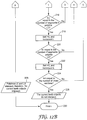
- FIGS. 12A and 12B are a flowchart illustrating one example process that modeling software 20 may utilize to determine whether two teeth objects intersect based on a set of cross-sections like those described above. This method may, for example, be used in the flowchart of FIGS. 3A and 3B at reference numeral 106 and again at reference numeral 122.
- tooth packing control module 24 chooses a first segment on a first one of the teeth and tests that first segment for intersection with all of the segments on the second tooth. Then tooth packing control module 24 chooses a second segment on the first tooth and tests that second segment for intersection with all of the segments on the second tooth, and so on until all of the segments in the current polyline on the first tooth have been tested for intersection with all of the segments in the current polyline on the second tooth. The process continues until all cross-sections for the two teeth have been tested for intersection. If any of the segments are found to intersect, tooth packing control module 24 determines that the two teeth intersect. If none of the segments in any of the polylines are found to intersect, tooth packing control module 24 determines that the two teeth do not intersect.
- tooth packing control module 24 first defines an index k (202). Index k represents the current cross-section (C k ), and is set to zero (204) on the first iteration of the process. Tooth packing control module 24 next defines two polylines L0 and L1 in cross-section C k that will be tested for intersection.
- L0 represents the polyline on a first one of the teeth being checked for intersection. For example, L0 may represent polyline 180A of cross-section C0 in FIGS. 10B or 11B .
- L1 represents the polyline on the second, adjacent tooth being checked for intersection. For example, L1 may represent polyline 180B of cross-section C0 in FIGS. 10B or 11B .
- Table 1 illustrates one example of how cross-sections C k and polylines L0 and L1 may correspond.
- Table 1 C k L0 L1 C0 180A 180B C1 181A 181B C2 182A 182B C3 183A 183B C4 184A 184B
- tooth packing control module 24 breaks each polyline L0 and L1 into smaller segments. Each segment in polyline L0 is checked for intersection with each segment in polyline L1. In one embodiment, tooth packing control module 24 accomplishes this segment comparison by defining two indices, i and j (206). Index i represents the i th segment of polyline L0, and index j represents the j th segment of polyline L1.
- FIGS. 13, 14 and 15 Examples of intersecting segments are shown in FIGS. 13, 14 and 15.
- FIG. 13 shows an enlarged illustration of cross-section C4 (see FIG. 11B ), polyline L0 184A, polyline L1 184B, segments 190A and 190B and segments 192A and 192B.
- segments 190A and 190B intersect, as do segments 192A and 192B.
- tooth packing control module 24 finds these intersecting segments, it determines that the corresponding teeth intersect.
- FIG. 14 shows an enlarged illustration of cross-section C3 (see FIG. 11B ), polyline L0 183A, polyline L1 183B, intersecting line segments 194A and 194B and intersecting line segments 196A and 196B.
- FIG. 15 shows an enlarged illustration of cross-section C0 (see FIG. 11B ), polyline L0 180A, polyline L1 180B, intersecting line segments 198A and 198B.
- tooth packing control module 24 sets indices i and j to zero (210) for the first iteration. Tooth packing control module 24 next determines whether the current polyline segments L0 i and L1 j intersect (212). To do this, tooth packing control module 24 may use any of a number of different intersection detection methods. For example, tooth packing control module 24 may compare the equations describing the current line segments to determine whether they intersect. If the current segments do intersect, tooth packing control module 24 determines that the corresponding teeth intersect (228). In one embodiment, the process may finish (230) at this point. In another embodiment, tooth packing control module 24 may store the intersection information and continue checking all of the polylines for intersection, storing any relevant intersection information, until all of the polylines have been checked.
- tooth packing control module 24 increments j (214) and determines whether all segments on polyline L1 have been checked (216). If not, tooth packing control module 24 checks the current polyline segment L0 i for intersection with the next polyline segment in polyline L1, L1 j . Tooth packing control module continues to increment j until all polyline segments L1 j are checked for intersection with the current polyline segment L0 i . Then, tooth packing control module 24 resets j to 0 and increments i (218) to check the next segment on polyline L0. Tooth packing control module 24 continues the process until all segments in polyline L0 are checked with all segments in polyline L1 (220).
- tooth packing control module 24 increments index k (222) to check the next cross-section C k (for example polyline C1 in FIG. 10B or FIG. 11B ). If after checking all cross-sections C k for intersection (224) there are no intersecting polyline segments, tooth packing control module 24 determines that the teeth do not intersect (226). The process may then finish (230).
- Client computing device 4 may move orthodontic objects along the virtual archwire within the 3D environment in accordance with the tooth packing algorithm described above. Client computing device may also move orthodontic objects in response to input from the orthodontic practitioner 8. In either case, to actually move the orthodontic objects along the virtual archwire, modeling software 20 may include some manner of representing (in other words, defining) the virtual archwire within the 3D environment. In one embodiment, the virtual archwire may be represented as a series of geometric segments.
- That application describes techniques for moving an orthodontic object (e.g., one or more orthodontic appliances and/or their associated teeth) from one position to another along a virtual archwire.
- the application describes representing an archwire within a three-dimensional (3D) environment with a plurality of segments, receiving input indicative of movement of an orthodontic object along the archwire, and moving the orthodontic object within the 3D environment as indicated along the archwire based on the plurality of segments.
Landscapes
- Health & Medical Sciences (AREA)
- Oral & Maxillofacial Surgery (AREA)
- Dentistry (AREA)
- Epidemiology (AREA)
- Life Sciences & Earth Sciences (AREA)
- Animal Behavior & Ethology (AREA)
- General Health & Medical Sciences (AREA)
- Public Health (AREA)
- Veterinary Medicine (AREA)
- Dental Tools And Instruments Or Auxiliary Dental Instruments (AREA)
- Processing Or Creating Images (AREA)
Claims (15)
- Procédé comprenant :
la détermination automatique de positions d'objets orthodontiques le long d'un arc dentaire au sein d'un environnement tridimensionnel (3D) sur la base d'une prescription orthodontique proposée, dans lequel chacun des objets orthodontiques représente une dent de l'arcade dentaire du patient, et dans lequel les positions sont déterminées de telle sorte que les objets orthodontiques ne se croisent pas, dans lequel la détermination automatique de positions des objets orthodontiques comprend :la mise en place d'une première dent au sein de l'environnement 3D ; etla mise en place d'une deuxième dent au sein de l'environnement 3D de telle sorte que la deuxième dent est positionnée dans les limites d'une tolérance souhaitée de la première dent, dans lequel la mise en place de la deuxième dent comprend :le fait de déterminer si la première dent et la deuxième dent se croisent au sein de l'environnement 3D ;le déplacement de la deuxième dent dans une direction mésiale lorsque la première dent et la deuxième dent ne se croisent pas ; etle déplacement de la deuxième dent dans une direction distale lorsque la première dent et la deuxième dent se croisent ; etl'affichage d'une représentation numérique des objets orthodontiques aux positions déterminées. - Procédé selon la revendication 1, comprenant en outre la réception de la prescription orthodontique proposée depuis l'un parmi un praticien ou une base de données.
- Procédé selon la revendication 1, dans lequel la prescription orthodontique proposée inclut une pluralité d'appareils orthodontiques associés chacun à une dent différente d'une pluralité de dents dans une arcade dentaire et un arc dentaire reçu dans une encoche de chacun des appareils orthodontiques.
- Procédé selon la revendication 3 dans lequel la prescription orthodontique proposée inclut un ensemble d'attributs géométriques associés à chaque appareil orthodontique.
- Procédé selon la revendication 3 dans lequel la prescription orthodontique proposée inclut des positions et orientations relatives de chacun des appareils orthodontiques par rapport aux dents associées.
- Procédé selon la revendication 3, dans lequel la détermination automatique de positions d'objets orthodontiques comprend le déplacement de chacun parmi la pluralité d'appareils orthodontiques et la pluralité associée de dents au sein de l'environnement 3D par rapport à l'arc dentaire.
- Procédé selon la revendication 3, dans lequel l'appareil orthodontique est choisi parmi l'ensemble d'un bracket orthodontique, un tube buccal, une gaine et un bouton.
- Procédé selon la revendication 1, dans lequel la prescription orthodontique proposée est reçue d'un praticien via une interface utilisateur.
- Procédé selon la revendication 1, dans lequel la détermination automatique de positions d'objets orthodontiques comprend en outre la mise en place de dents ultérieures au sein de l'environnement 3D de telle sorte que chacune des dents ultérieures est positionnée dans les limites de la tolérance souhaitée d'une dent précédemment placée.
- Procédé selon la revendication 1, dans lequel la mise en place d'une deuxième dent comprend la mise en place de la deuxième dent au sein de l'environnement 3D à une distance définie à l'écart de la première dent, et dans lequel la mise en place de la deuxième dent comprend en outre le déplacement de la deuxième dent dans une direction mésiale d'une moitié de la distance définie en direction de la première dent lorsque la première dent et la deuxième dent ne se croisent pas.
- Procédé selon la revendication 1, dans lequel la mise en place d'une deuxième dent comprend la mise en place de la deuxième dent au sein de l'environnement 3D à une distance définie à l'écart de la première dent, et dans lequel la mise en place de la deuxième dent comprend en outre le déplacement de la deuxième dent dans une direction distale d'une moitié de la distance définie à l'écart de la première dent lorsque la première dent et la deuxième dent se croisent.
- Procédé selon la revendication 1, dans lequel le fait de déterminer si la première dent et la deuxième dent se croisent comprend :la génération de coupes transversales de la première dent et de coupes transversales correspondantes de la deuxième dent ;la comparaison de chaque coupe transversale de la première dent avec la coupe transversale correspondante de la deuxième dent ; etfait de déterminer que la première dent et la deuxième dent se croisent si l'une quelconque coupe transversale de la première dent croise la coupe transversale correspondante de la deuxième dent.
- Procédé selon la revendication 12, dans lequel l'arc dentaire définit un plan d'arc dentaire, et dans lequel la génération de coupes transversales de la première dent et de coupes transversales correspondantes de la deuxième dent comprend :
la définition d'une pluralité de plans, dans lequel chacun des plans est parallèle au plan d'arc dentaire et dans lequel chacun des plans croise la première dent et la deuxième dent dans l'environnement 3D pour produire des coupes transversales de la première dent et les coupes transversales correspondantes de la deuxième dent. - Système comprenant :un dispositif informatique ; etun logiciel de modélisation s'exécutant sur le dispositif informatique, dans lequel le logiciel de modélisation comprend :un module de commande d'empilement de dents qui détermine automatiquement des positions d'objets orthodontiques le long d'un arc dentaire au sein d'un environnement tridimensionnel (3D) sur la base d'une prescription orthodontique proposée, dans lequel chacun des objets orthodontiques représente une dent de l'arcade dentaire du patient, et dans lequel les positions sont déterminées de telle sorte que les objets orthodontiques ne se croisent pas, et dans lequel le module de commande d'empilement de dents :place une première dent le long d'un arc dentaire dans un premier quadrant de l'arcade dentaire ; etplace une deuxième dent le long de l'arc dentaire dans le premier quadrant de l'arcade dentaire de telle sorte que la première dent et la deuxième dent sont positionnées dans les limites d'une tolérance souhaitée l'une par rapport à l'autre, dans lequel la mise en place de la deuxième dent comprend :le fait de déterminer si la première dent et la deuxième dent se croisent ;le déplacement de la deuxième dent dans une direction mésiale au sein de l'environnement 3D lorsque la première dent et la deuxième dent ne se croisent pas ; etle déplacement de la deuxième dent dans une direction distale au sein de l'environnement 3D lorsque la première dent et la deuxième dent se croisent ; etune interface utilisateur qui affiche une représentation numérique des objets orthodontiques aux positions déterminées.
- Système selon la revendication 14, dans lequel la prescription orthodontique proposée inclut une pluralité d'appareils orthodontiques associés chacun à l'une différente parmi une pluralité de dents dans l'arcade dentaire et un arc dentaire reçu dans une encoche de chaque appareil orthodontique.
Applications Claiming Priority (2)
| Application Number | Priority Date | Filing Date | Title |
|---|---|---|---|
| US10/959,624 US7291011B2 (en) | 2004-10-06 | 2004-10-06 | Placing orthodontic objects along an archwire within a three-dimensional (3D) environment |
| PCT/US2005/031549 WO2006041597A2 (fr) | 2004-10-06 | 2005-09-02 | Mise en place d'objets orthodontiques le long d'un arc dentaire dans un environnement tridimensionnel (3d) |
Publications (3)
| Publication Number | Publication Date |
|---|---|
| EP1816976A2 EP1816976A2 (fr) | 2007-08-15 |
| EP1816976A4 EP1816976A4 (fr) | 2012-12-05 |
| EP1816976B1 true EP1816976B1 (fr) | 2019-10-23 |
Family
ID=36125954
Family Applications (1)
| Application Number | Title | Priority Date | Filing Date |
|---|---|---|---|
| EP05793948.0A Expired - Lifetime EP1816976B1 (fr) | 2004-10-06 | 2005-09-02 | Mise en place d'objets orthodontiques le long d'un arc dentaire dans un environnement tridimensionnel (3d) |
Country Status (6)
| Country | Link |
|---|---|
| US (1) | US7291011B2 (fr) |
| EP (1) | EP1816976B1 (fr) |
| JP (1) | JP5021482B2 (fr) |
| AU (1) | AU2005294679B2 (fr) |
| DK (1) | DK1816976T3 (fr) |
| WO (1) | WO2006041597A2 (fr) |
Families Citing this family (27)
| Publication number | Priority date | Publication date | Assignee | Title |
|---|---|---|---|---|
| US8308478B2 (en) * | 2005-03-01 | 2012-11-13 | Dentsply International Inc. | Methods for indirect bonding of orthodontic appliances |
| US7940258B2 (en) * | 2006-04-10 | 2011-05-10 | 3M Innovative Properties Company | Automatic adjustment of an orthodontic bracket to a desired mesio-distal position within a three-dimensional (3D) environment |
| US7993133B2 (en) * | 2006-10-20 | 2011-08-09 | 3M Innovative Properties Company | Digital orthodontic treatment planning |
| GB0724992D0 (en) * | 2007-12-21 | 2008-01-30 | Materialise Nv | Tooth improvement |
| WO2009126433A2 (fr) | 2008-04-09 | 2009-10-15 | 3M Innovative Properties Company | Appareil orthodontique lingual avec section amovible |
| US9503282B2 (en) | 2008-09-19 | 2016-11-22 | 3M Innovative Properties Company | Methods and systems for determining the positions of orthodontic appliances |
| WO2010070710A1 (fr) * | 2008-12-18 | 2010-06-24 | Hiro Toshiaki | Procédé d'assistance pour le placement d'un bracket orthodontique et appareil d'assistance au placement |
| US20100238184A1 (en) * | 2009-03-19 | 2010-09-23 | Michael Janicki | Method and apparatus for three-dimensional visualization in mobile devices |
| DE102010063124A1 (de) * | 2010-12-15 | 2012-06-21 | Sirona Dental Systems Gmbh | Vorrichtung und Verfahren zur Bearbeitung eines virtuellen 3D-Models mittels eines virtuellen Werkzeugs |
| WO2012112867A2 (fr) | 2011-02-18 | 2012-08-23 | 3M Innovative Properties Company | Installations orthodontiques numériques |
| CN107427338A (zh) | 2015-03-13 | 2017-12-01 | 3M创新有限公司 | 包括弓形构件的正畸器具 |
| EP3267926A1 (fr) | 2015-03-13 | 2018-01-17 | 3M Innovative Properties Company | Appareil orthodontique comprenant un élément formant arc |
| CN108348306B (zh) | 2015-11-02 | 2021-01-15 | 3M创新有限公司 | 具有连续形状记忆的正畸器具 |
| BR112018011378B1 (pt) | 2015-12-06 | 2021-09-08 | Brius Technologies, Inc. | Aparelhos ortodônticos para reposicionamento de dentes |
| KR20190022777A (ko) | 2016-06-30 | 2019-03-06 | 쓰리엠 이노베이티브 프로퍼티즈 컴파니 | 고점성 성분을 포함하는 인쇄가능 조성물 및 그로부터 3d 물품을 생성하는 방법 |
| WO2018057118A1 (fr) * | 2016-09-21 | 2018-03-29 | Premier Orthodontic Designs, Lllp | Bracket orthodontique |
| US10809697B2 (en) | 2017-03-20 | 2020-10-20 | Advanced Orthodontic Solutions | Wire path design tool |
| US10687917B2 (en) * | 2017-07-14 | 2020-06-23 | Dental Smartmirror, Inc. | Using immersive photographs to guide placement of orthodontic brackets, and applications thereof |
| WO2020223744A1 (fr) | 2019-05-02 | 2020-11-05 | Brius Technologies, Inc. | Appareils dentaires et procédés de fabrication associés |
| JP2022550278A (ja) | 2019-09-18 | 2022-12-01 | スリーエム イノベイティブ プロパティズ カンパニー | 歯肉方向に延びたチャネルを含むトランスファー装置及び関連する製造方法 |
| EP4138719B1 (fr) | 2020-04-24 | 2024-05-29 | Solventum Intellectual Properties Company | Plateau de collage indirecte pour coller des appareils orthodontiques et procédés de fabrication de celui-ci |
| US12144700B2 (en) | 2020-11-05 | 2024-11-19 | Brius Technologies, Inc. | Dental appliances and associated systems and methods |
| US11504212B2 (en) | 2021-03-25 | 2022-11-22 | Brius Technologies, Inc. | Orthodontic treatment and associated devices, systems, and methods |
| CN118591843A (zh) | 2022-02-25 | 2024-09-03 | 舒万诺知识产权公司 | 用于口腔护理处理时间线的可视化的系统和方法 |
| EP4584089A1 (fr) | 2022-09-09 | 2025-07-16 | Solventum Intellectual Properties Company | Appareil de transfert pour appareils orthodontiques et procédés de fabrication associés |
| EP4633952A1 (fr) | 2022-12-14 | 2025-10-22 | Solventum Intellectual Properties Company | Appareil de transfert pour appareils orthodontiques et procédés de fabrication associés |
| WO2025253200A1 (fr) | 2024-06-07 | 2025-12-11 | Solventum Intellectual Properties Company | Appareil de transfert pour appareils orthodontiques et procédés de fabrication associés |
Family Cites Families (25)
| Publication number | Priority date | Publication date | Assignee | Title |
|---|---|---|---|---|
| US5474448A (en) * | 1990-01-19 | 1995-12-12 | Ormco Corporation | Low profile orthodontic appliance |
| JP3672966B2 (ja) * | 1995-04-14 | 2005-07-20 | 株式会社ユニスン | 歯科用予測模型の作成方法および作成装置 |
| DE69626287T2 (de) | 1995-07-21 | 2003-11-27 | Cadent Ltd., Or Yehuda | Verfahren und system zur dreidimensionalen bilderfassung von zähnen |
| IL120867A0 (en) | 1997-05-20 | 1997-09-30 | Cadent Ltd | Computer user interface for orthodontic use |
| US5879158A (en) | 1997-05-20 | 1999-03-09 | Doyle; Walter A. | Orthodontic bracketing system and method therefor |
| IL120892A (en) | 1997-05-22 | 2000-08-31 | Cadent Ltd | Method for obtaining a dental occlusion map |
| US6471511B1 (en) * | 1997-06-20 | 2002-10-29 | Align Technology, Inc. | Defining tooth-moving appliances computationally |
| US6152731A (en) | 1997-09-22 | 2000-11-28 | 3M Innovative Properties Company | Methods for use in dental articulation |
| US6334772B1 (en) | 1997-09-30 | 2002-01-01 | Cadent Ltd. | Placing an orthodontic element on a tooth surface |
| IL122807A0 (en) | 1997-12-30 | 1998-08-16 | Cadent Ltd | Virtual orthodontic treatment |
| IL125659A (en) | 1998-08-05 | 2002-09-12 | Cadent Ltd | Method and device for three-dimensional simulation of a structure |
| US6123544A (en) | 1998-12-18 | 2000-09-26 | 3M Innovative Properties Company | Method and apparatus for precise bond placement of orthodontic appliances |
| US6318994B1 (en) * | 1999-05-13 | 2001-11-20 | Align Technology, Inc | Tooth path treatment plan |
| US7160110B2 (en) * | 1999-11-30 | 2007-01-09 | Orametrix, Inc. | Three-dimensional occlusal and interproximal contact detection and display using virtual tooth models |
| US6648640B2 (en) | 1999-11-30 | 2003-11-18 | Ora Metrix, Inc. | Interactive orthodontic care system based on intra-oral scanning of teeth |
| US6632089B2 (en) * | 1999-11-30 | 2003-10-14 | Orametrix, Inc. | Orthodontic treatment planning with user-specified simulation of tooth movement |
| US6971873B2 (en) * | 2000-04-19 | 2005-12-06 | Orametrix, Inc. | Virtual bracket library and uses thereof in orthodontic treatment planning |
| US6457978B1 (en) | 2000-10-10 | 2002-10-01 | Cadent, Inc. | Method and apparatus for arranging cable connectors to allow for easier cable installation |
| US7080979B2 (en) | 2001-04-13 | 2006-07-25 | Orametrix, Inc. | Method and workstation for generating virtual tooth models from three-dimensional tooth data |
| US7387511B2 (en) | 2002-01-22 | 2008-06-17 | Geodigm Corporation | Method and apparatus using a scanned image for automatically placing bracket in pre-determined locations |
| US7155373B2 (en) * | 2002-02-22 | 2006-12-26 | 3M Innovative Properties Company | Selection of orthodontic brackets |
| US7074039B2 (en) | 2002-05-02 | 2006-07-11 | Cadent Ltd. | Method and system for assessing the outcome of an orthodontic treatment |
| US7160107B2 (en) | 2002-05-02 | 2007-01-09 | Cadent Ltd. | Method and system for assessing the outcome of an orthodontic treatment |
| US7033327B2 (en) | 2002-09-13 | 2006-04-25 | 3M Innovative Properties Company | Method of determining the long axis of an object |
| US7637740B2 (en) * | 2004-02-27 | 2009-12-29 | Align Technology, Inc. | Systems and methods for temporally staging teeth |
-
2004
- 2004-10-06 US US10/959,624 patent/US7291011B2/en not_active Expired - Lifetime
-
2005
- 2005-09-02 AU AU2005294679A patent/AU2005294679B2/en not_active Ceased
- 2005-09-02 JP JP2007535687A patent/JP5021482B2/ja not_active Expired - Fee Related
- 2005-09-02 DK DK05793948.0T patent/DK1816976T3/da active
- 2005-09-02 EP EP05793948.0A patent/EP1816976B1/fr not_active Expired - Lifetime
- 2005-09-02 WO PCT/US2005/031549 patent/WO2006041597A2/fr not_active Ceased
Also Published As
| Publication number | Publication date |
|---|---|
| WO2006041597A3 (fr) | 2007-04-12 |
| EP1816976A2 (fr) | 2007-08-15 |
| AU2005294679A1 (en) | 2006-04-20 |
| JP5021482B2 (ja) | 2012-09-05 |
| WO2006041597A2 (fr) | 2006-04-20 |
| DK1816976T3 (da) | 2020-01-27 |
| US7291011B2 (en) | 2007-11-06 |
| EP1816976A4 (fr) | 2012-12-05 |
| US20060073435A1 (en) | 2006-04-06 |
| JP2008515536A (ja) | 2008-05-15 |
| AU2005294679B2 (en) | 2011-09-15 |
Similar Documents
| Publication | Publication Date | Title |
|---|---|---|
| EP1816976B1 (fr) | Mise en place d'objets orthodontiques le long d'un arc dentaire dans un environnement tridimensionnel (3d) | |
| EP2008231B1 (fr) | Réglage automatique d'un dispositif orthodontique sur une position mésiodistale désirée dans un environnement tridimensionnel (3d) | |
| US7354268B2 (en) | Movement of orthodontic objects along a virtual archwire within a three-dimensional (3D) environment | |
| US7993133B2 (en) | Digital orthodontic treatment planning | |
| AU2005277993B2 (en) | Automatic adjustment of an orthodontic bracket to a desired occlusal height within a three-dimensional (3D) environment | |
| EP1658821B1 (fr) | Procédé et appareil permettant de sélectionner une prescription pour un appareil orthodontique | |
| US9844419B2 (en) | Custom orthodontic appliance system and method | |
| EP1711120B1 (fr) | Guides planaires pour faciliter visuellement le placement d'un appareil orthodontique dans un environnement tridimensionnel (3d) | |
| US8512037B2 (en) | Custom orthodontic appliance system and method | |
| US20260007488A1 (en) | Orthodontic treatment evaluation |
Legal Events
| Date | Code | Title | Description |
|---|---|---|---|
| PUAI | Public reference made under article 153(3) epc to a published international application that has entered the european phase |
Free format text: ORIGINAL CODE: 0009012 |
|
| 17P | Request for examination filed |
Effective date: 20070406 |
|
| AK | Designated contracting states |
Kind code of ref document: A2 Designated state(s): AT BE BG CH CY CZ DE DK EE ES FI FR GB GR HU IE IS IT LI LT LU LV MC NL PL PT RO SE SI SK TR |
|
| AX | Request for extension of the european patent |
Extension state: AL BA HR MK YU |
|
| DAX | Request for extension of the european patent (deleted) | ||
| A4 | Supplementary search report drawn up and despatched |
Effective date: 20121107 |
|
| RIC1 | Information provided on ipc code assigned before grant |
Ipc: A61C 7/00 20060101AFI20121101BHEP |
|
| GRAP | Despatch of communication of intention to grant a patent |
Free format text: ORIGINAL CODE: EPIDOSNIGR1 |
|
| STAA | Information on the status of an ep patent application or granted ep patent |
Free format text: STATUS: GRANT OF PATENT IS INTENDED |
|
| INTG | Intention to grant announced |
Effective date: 20190404 |
|
| RIN1 | Information on inventor provided before grant (corrected) |
Inventor name: RABY, RICHARD, E. Inventor name: STARK, NICHOLAS, A. |
|
| GRAS | Grant fee paid |
Free format text: ORIGINAL CODE: EPIDOSNIGR3 |
|
| GRAA | (expected) grant |
Free format text: ORIGINAL CODE: 0009210 |
|
| STAA | Information on the status of an ep patent application or granted ep patent |
Free format text: STATUS: THE PATENT HAS BEEN GRANTED |
|
| AK | Designated contracting states |
Kind code of ref document: B1 Designated state(s): AT BE BG CH CY CZ DE DK EE ES FI FR GB GR HU IE IS IT LI LT LU LV MC NL PL PT RO SE SI SK TR |
|
| REG | Reference to a national code |
Ref country code: GB Ref legal event code: FG4D |
|
| REG | Reference to a national code |
Ref country code: CH Ref legal event code: EP |
|
| REG | Reference to a national code |
Ref country code: IE Ref legal event code: FG4D |
|
| REG | Reference to a national code |
Ref country code: DE Ref legal event code: R096 Ref document number: 602005056342 Country of ref document: DE |
|
| REG | Reference to a national code |
Ref country code: AT Ref legal event code: REF Ref document number: 1192800 Country of ref document: AT Kind code of ref document: T Effective date: 20191115 |
|
| REG | Reference to a national code |
Ref country code: DK Ref legal event code: T3 Effective date: 20200120 |
|
| REG | Reference to a national code |
Ref country code: NL Ref legal event code: MP Effective date: 20191023 |
|
| REG | Reference to a national code |
Ref country code: LT Ref legal event code: MG4D |
|
| PG25 | Lapsed in a contracting state [announced via postgrant information from national office to epo] |
Ref country code: PL Free format text: LAPSE BECAUSE OF FAILURE TO SUBMIT A TRANSLATION OF THE DESCRIPTION OR TO PAY THE FEE WITHIN THE PRESCRIBED TIME-LIMIT Effective date: 20191023 Ref country code: GR Free format text: LAPSE BECAUSE OF FAILURE TO SUBMIT A TRANSLATION OF THE DESCRIPTION OR TO PAY THE FEE WITHIN THE PRESCRIBED TIME-LIMIT Effective date: 20200124 Ref country code: NL Free format text: LAPSE BECAUSE OF FAILURE TO SUBMIT A TRANSLATION OF THE DESCRIPTION OR TO PAY THE FEE WITHIN THE PRESCRIBED TIME-LIMIT Effective date: 20191023 Ref country code: ES Free format text: LAPSE BECAUSE OF FAILURE TO SUBMIT A TRANSLATION OF THE DESCRIPTION OR TO PAY THE FEE WITHIN THE PRESCRIBED TIME-LIMIT Effective date: 20191023 Ref country code: LT Free format text: LAPSE BECAUSE OF FAILURE TO SUBMIT A TRANSLATION OF THE DESCRIPTION OR TO PAY THE FEE WITHIN THE PRESCRIBED TIME-LIMIT Effective date: 20191023 Ref country code: LV Free format text: LAPSE BECAUSE OF FAILURE TO SUBMIT A TRANSLATION OF THE DESCRIPTION OR TO PAY THE FEE WITHIN THE PRESCRIBED TIME-LIMIT Effective date: 20191023 Ref country code: SE Free format text: LAPSE BECAUSE OF FAILURE TO SUBMIT A TRANSLATION OF THE DESCRIPTION OR TO PAY THE FEE WITHIN THE PRESCRIBED TIME-LIMIT Effective date: 20191023 Ref country code: BG Free format text: LAPSE BECAUSE OF FAILURE TO SUBMIT A TRANSLATION OF THE DESCRIPTION OR TO PAY THE FEE WITHIN THE PRESCRIBED TIME-LIMIT Effective date: 20200123 Ref country code: FI Free format text: LAPSE BECAUSE OF FAILURE TO SUBMIT A TRANSLATION OF THE DESCRIPTION OR TO PAY THE FEE WITHIN THE PRESCRIBED TIME-LIMIT Effective date: 20191023 Ref country code: PT Free format text: LAPSE BECAUSE OF FAILURE TO SUBMIT A TRANSLATION OF THE DESCRIPTION OR TO PAY THE FEE WITHIN THE PRESCRIBED TIME-LIMIT Effective date: 20200224 |
|
| PG25 | Lapsed in a contracting state [announced via postgrant information from national office to epo] |
Ref country code: IS Free format text: LAPSE BECAUSE OF FAILURE TO SUBMIT A TRANSLATION OF THE DESCRIPTION OR TO PAY THE FEE WITHIN THE PRESCRIBED TIME-LIMIT Effective date: 20200224 |
|
| REG | Reference to a national code |
Ref country code: DE Ref legal event code: R097 Ref document number: 602005056342 Country of ref document: DE |
|
| PG2D | Information on lapse in contracting state deleted |
Ref country code: IS |
|
| PG25 | Lapsed in a contracting state [announced via postgrant information from national office to epo] |
Ref country code: EE Free format text: LAPSE BECAUSE OF FAILURE TO SUBMIT A TRANSLATION OF THE DESCRIPTION OR TO PAY THE FEE WITHIN THE PRESCRIBED TIME-LIMIT Effective date: 20191023 Ref country code: CZ Free format text: LAPSE BECAUSE OF FAILURE TO SUBMIT A TRANSLATION OF THE DESCRIPTION OR TO PAY THE FEE WITHIN THE PRESCRIBED TIME-LIMIT Effective date: 20191023 Ref country code: RO Free format text: LAPSE BECAUSE OF FAILURE TO SUBMIT A TRANSLATION OF THE DESCRIPTION OR TO PAY THE FEE WITHIN THE PRESCRIBED TIME-LIMIT Effective date: 20191023 Ref country code: IS Free format text: LAPSE BECAUSE OF FAILURE TO SUBMIT A TRANSLATION OF THE DESCRIPTION OR TO PAY THE FEE WITHIN THE PRESCRIBED TIME-LIMIT Effective date: 20200223 |
|
| REG | Reference to a national code |
Ref country code: AT Ref legal event code: MK05 Ref document number: 1192800 Country of ref document: AT Kind code of ref document: T Effective date: 20191023 |
|
| PLBE | No opposition filed within time limit |
Free format text: ORIGINAL CODE: 0009261 |
|
| STAA | Information on the status of an ep patent application or granted ep patent |
Free format text: STATUS: NO OPPOSITION FILED WITHIN TIME LIMIT |
|
| PG25 | Lapsed in a contracting state [announced via postgrant information from national office to epo] |
Ref country code: IT Free format text: LAPSE BECAUSE OF FAILURE TO SUBMIT A TRANSLATION OF THE DESCRIPTION OR TO PAY THE FEE WITHIN THE PRESCRIBED TIME-LIMIT Effective date: 20191023 Ref country code: SK Free format text: LAPSE BECAUSE OF FAILURE TO SUBMIT A TRANSLATION OF THE DESCRIPTION OR TO PAY THE FEE WITHIN THE PRESCRIBED TIME-LIMIT Effective date: 20191023 |
|
| 26N | No opposition filed |
Effective date: 20200724 |
|
| PG25 | Lapsed in a contracting state [announced via postgrant information from national office to epo] |
Ref country code: AT Free format text: LAPSE BECAUSE OF FAILURE TO SUBMIT A TRANSLATION OF THE DESCRIPTION OR TO PAY THE FEE WITHIN THE PRESCRIBED TIME-LIMIT Effective date: 20191023 Ref country code: SI Free format text: LAPSE BECAUSE OF FAILURE TO SUBMIT A TRANSLATION OF THE DESCRIPTION OR TO PAY THE FEE WITHIN THE PRESCRIBED TIME-LIMIT Effective date: 20191023 |
|
| PG25 | Lapsed in a contracting state [announced via postgrant information from national office to epo] |
Ref country code: MC Free format text: LAPSE BECAUSE OF FAILURE TO SUBMIT A TRANSLATION OF THE DESCRIPTION OR TO PAY THE FEE WITHIN THE PRESCRIBED TIME-LIMIT Effective date: 20191023 |
|
| REG | Reference to a national code |
Ref country code: CH Ref legal event code: PL |
|
| GBPC | Gb: european patent ceased through non-payment of renewal fee |
Effective date: 20200902 |
|
| REG | Reference to a national code |
Ref country code: BE Ref legal event code: MM Effective date: 20200930 |
|
| PG25 | Lapsed in a contracting state [announced via postgrant information from national office to epo] |
Ref country code: LU Free format text: LAPSE BECAUSE OF NON-PAYMENT OF DUE FEES Effective date: 20200902 |
|
| PG25 | Lapsed in a contracting state [announced via postgrant information from national office to epo] |
Ref country code: CH Free format text: LAPSE BECAUSE OF NON-PAYMENT OF DUE FEES Effective date: 20200930 Ref country code: BE Free format text: LAPSE BECAUSE OF NON-PAYMENT OF DUE FEES Effective date: 20200930 Ref country code: GB Free format text: LAPSE BECAUSE OF NON-PAYMENT OF DUE FEES Effective date: 20200902 Ref country code: LI Free format text: LAPSE BECAUSE OF NON-PAYMENT OF DUE FEES Effective date: 20200930 Ref country code: IE Free format text: LAPSE BECAUSE OF NON-PAYMENT OF DUE FEES Effective date: 20200902 |
|
| PGFP | Annual fee paid to national office [announced via postgrant information from national office to epo] |
Ref country code: FR Payment date: 20210820 Year of fee payment: 17 |
|
| PGFP | Annual fee paid to national office [announced via postgrant information from national office to epo] |
Ref country code: DK Payment date: 20210823 Year of fee payment: 17 |
|
| PG25 | Lapsed in a contracting state [announced via postgrant information from national office to epo] |
Ref country code: TR Free format text: LAPSE BECAUSE OF FAILURE TO SUBMIT A TRANSLATION OF THE DESCRIPTION OR TO PAY THE FEE WITHIN THE PRESCRIBED TIME-LIMIT Effective date: 20191023 Ref country code: CY Free format text: LAPSE BECAUSE OF FAILURE TO SUBMIT A TRANSLATION OF THE DESCRIPTION OR TO PAY THE FEE WITHIN THE PRESCRIBED TIME-LIMIT Effective date: 20191023 |
|
| REG | Reference to a national code |
Ref country code: DK Ref legal event code: EBP Effective date: 20220930 |
|
| P01 | Opt-out of the competence of the unified patent court (upc) registered |
Effective date: 20230530 |
|
| PG25 | Lapsed in a contracting state [announced via postgrant information from national office to epo] |
Ref country code: FR Free format text: LAPSE BECAUSE OF NON-PAYMENT OF DUE FEES Effective date: 20220930 |
|
| PG25 | Lapsed in a contracting state [announced via postgrant information from national office to epo] |
Ref country code: DK Free format text: LAPSE BECAUSE OF NON-PAYMENT OF DUE FEES Effective date: 20220930 |
|
| REG | Reference to a national code |
Ref country code: DE Ref legal event code: R081 Ref document number: 602005056342 Country of ref document: DE Owner name: SOLVENTUM INTELLECTUAL PROPERTIES CO. (N.D.GES, US Free format text: FORMER OWNER: 3M INNOVATIVE PROPERTIES COMPANY, ST. PAUL, MN, US |
|
| PGFP | Annual fee paid to national office [announced via postgrant information from national office to epo] |
Ref country code: DE Payment date: 20240820 Year of fee payment: 20 |
|
| REG | Reference to a national code |
Ref country code: DE Ref legal event code: R071 Ref document number: 602005056342 Country of ref document: DE |