EP1817063B1 - Dispositif pour exposer en continu des liquides absorbants a des rayonnements ultraviolets - Google Patents
Dispositif pour exposer en continu des liquides absorbants a des rayonnements ultraviolets Download PDFInfo
- Publication number
- EP1817063B1 EP1817063B1 EP05850427A EP05850427A EP1817063B1 EP 1817063 B1 EP1817063 B1 EP 1817063B1 EP 05850427 A EP05850427 A EP 05850427A EP 05850427 A EP05850427 A EP 05850427A EP 1817063 B1 EP1817063 B1 EP 1817063B1
- Authority
- EP
- European Patent Office
- Prior art keywords
- radiation
- flow
- casing tube
- coolant
- irradiation
- Prior art date
- Legal status (The legal status is an assumption and is not a legal conclusion. Google has not performed a legal analysis and makes no representation as to the accuracy of the status listed.)
- Ceased
Links
Images


Classifications
-
- C—CHEMISTRY; METALLURGY
- C02—TREATMENT OF WATER, WASTE WATER, SEWAGE, OR SLUDGE
- C02F—TREATMENT OF WATER, WASTE WATER, SEWAGE, OR SLUDGE
- C02F1/00—Treatment of water, waste water, or sewage
- C02F1/30—Treatment of water, waste water, or sewage by irradiation
- C02F1/32—Treatment of water, waste water, or sewage by irradiation with ultraviolet light
- C02F1/325—Irradiation devices or lamp constructions
-
- A—HUMAN NECESSITIES
- A61—MEDICAL OR VETERINARY SCIENCE; HYGIENE
- A61L—METHODS OR APPARATUS FOR STERILISING MATERIALS OR OBJECTS IN GENERAL; DISINFECTION, STERILISATION OR DEODORISATION OF AIR; CHEMICAL ASPECTS OF BANDAGES, DRESSINGS, ABSORBENT PADS OR SURGICAL ARTICLES; MATERIALS FOR BANDAGES, DRESSINGS, ABSORBENT PADS OR SURGICAL ARTICLES
- A61L2/00—Disinfection or sterilisation of materials or objects, in general; Accessories therefor
- A61L2/02—Disinfection or sterilisation of materials or objects, in general; Accessories therefor using physical processes
- A61L2/08—Radiation
- A61L2/10—Ultraviolet [UV] radiation
-
- C—CHEMISTRY; METALLURGY
- C02—TREATMENT OF WATER, WASTE WATER, SEWAGE, OR SLUDGE
- C02F—TREATMENT OF WATER, WASTE WATER, SEWAGE, OR SLUDGE
- C02F2201/00—Apparatus for treatment of water, waste water or sewage
- C02F2201/32—Details relating to UV-irradiation devices
- C02F2201/322—Lamp arrangement
- C02F2201/3227—Units with two or more lamps
-
- C—CHEMISTRY; METALLURGY
- C02—TREATMENT OF WATER, WASTE WATER, SEWAGE, OR SLUDGE
- C02F—TREATMENT OF WATER, WASTE WATER, SEWAGE, OR SLUDGE
- C02F2201/00—Apparatus for treatment of water, waste water or sewage
- C02F2201/32—Details relating to UV-irradiation devices
- C02F2201/326—Lamp control systems
-
- C—CHEMISTRY; METALLURGY
- C02—TREATMENT OF WATER, WASTE WATER, SEWAGE, OR SLUDGE
- C02F—TREATMENT OF WATER, WASTE WATER, SEWAGE, OR SLUDGE
- C02F2303/00—Specific treatment goals
- C02F2303/04—Disinfection
-
- Y—GENERAL TAGGING OF NEW TECHNOLOGICAL DEVELOPMENTS; GENERAL TAGGING OF CROSS-SECTIONAL TECHNOLOGIES SPANNING OVER SEVERAL SECTIONS OF THE IPC; TECHNICAL SUBJECTS COVERED BY FORMER USPC CROSS-REFERENCE ART COLLECTIONS [XRACs] AND DIGESTS
- Y10—TECHNICAL SUBJECTS COVERED BY FORMER USPC
- Y10S—TECHNICAL SUBJECTS COVERED BY FORMER USPC CROSS-REFERENCE ART COLLECTIONS [XRACs] AND DIGESTS
- Y10S422/00—Chemical apparatus and process disinfecting, deodorizing, preserving, or sterilizing
- Y10S422/906—Plasma or ion generation means
Definitions
- the invention relates to a device for irradiating absorbent liquids, for example, to be disinfected wastewater with UV radiation.
- an on-site open rectangular drainage channel in the sewage treatment plant effluent is equipped with a set of low-pressure mercury radiators (Hg-ND radiators) aligned in the flow direction. It is each radiator is provided with a cylindrical shell of quartz, which is flowed around by the water to be treated.
- Hg-ND radiators low-pressure mercury radiators
- a module which consists of a stainless steel frame for holding the stacked cladding, a top cover to prevent the escape of harmful UV radiation, a connector for power supply and handles for removal in the vertical direction for maintenance purposes.
- a plurality of such modules are mounted parallel to each other in a fixedly mounted on the channel frame, which acts as a support, locking and cable channel.
- the US 5,124,131 describes a device for UV irradiation of waste water in the flow with at least two radiator assemblies, each with a cylindrical UV lamp around which a concentric cladding tube is arranged, wherein between the lamp and the cladding tube, a coolant for dissipating the heat of the lamp flows.
- the US 5,505,912 describes a cooling system for a reactor with UV lamps whose radiation irradiates a medium to be treated.
- the reactor system is configured to treat contaminants in the medium, with the UV lamps operating at operating temperatures above 300 ° C.
- the invention has for its object to provide a system for UV irradiation of absorbing liquids in the flow, which allows a uniform irradiation of the liquid, even at high flow rates.
- Another object of the invention is to propose such a device, which is inexpensive to manufacture.
- Yet another object of the invention is to provide a device for UV irradiation of absorbing liquids in the flow, in which the maintenance is reduced.
- a device for UV irradiation of absorbing liquids for example, to be disinfected wastewater in the flow through at least two UV lamp assemblies, characterized in that each lamp assembly has a cylindrical UV light source and three concentric cylindrical sheaths, wherein in a coolant for dissipating heat of the UV radiation source flows in a cavity between an inner and a middle cladding tube.
- the temperature at the outer cladding tube can be reduced, so that a burn-in of deposits on the cladding tube can be prevented. It is possible to increase the diameter of the outermost cladding tube, whereby a more uniform distribution of the irradiation intensity can be achieved.
- the diameter of the outer cladding tube is preferably between 80 and 250 mm, in particular between 120 and 200 mm.
- a gas filling of UV-permeable gas may be provided.
- the power density of the UV radiation sources is preferably at least 10 watts UV-C radiation per cm in the axial direction.
- the UV radiation sources can be arranged horizontally transversely to the flow direction, for example on a U-shaped steel wall, wherein the Hüllrohrenden are preferably sealed and provided with connections for energy and coolant.
- side mounting pits may be provided to allow access and replacement of the UV radiation sources.
- covers are preferably provided above the radiator assemblies.
- the radiator assemblies may be arranged in longitudinal section in the pattern of a two-dimensionally dense spherical packing in order to ensure the most uniform possible distribution of the irradiation intensity.
- a coolant circulating pump and a heat exchanger for discharging the heat to the absorbing liquid may be provided.
- the coolant used may preferably be distilled water, which has a very low UV absorption.
- alcohol such as ethanol or methanol may be added to prevent biological contamination of the coolant.
- the cladding tubes are preferably made of UV-transparent material such as quartz glass.
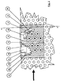
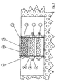
- the device according to the invention is in plan view in FIG. 1 , in longitudinal section view in FIG. 2 and in cross-sectional view against the flow direction in FIG FIG. 3 shown.
- the flow direction of the absorbent liquid is indicated by an arrow, but plays no role for the functioning of the device according to the invention.
- a U-shaped angled stainless steel wall 12 which is held by outer stiffeners 13 and arranged above the liquid surface struts 14 dimensionally stable, is installed in the channel 15.
- On each side is a coverable pit 16, 17, over which all electrical connections, control lines and pipes or hoses of the cooling circuit are routed for maintenance purposes.
- the radiator assemblies In the two lateral vertical areas of the stainless steel wall 12 there are pairs of opposite circular openings 18, in which the radiator assemblies, namely outer sheath 1, mounts and covers 8, 9 and 10 are waterproof sealed.
- the electrical connection cables and coolant hoses are not shown. They are most advantageously performed in a likewise not shown cable channel on the vertical stiffener 13.
- the irradiation zone is covered by one or more caissons made of stainless steel 19, 20, which ensure that even with a high water flow rate above the topmost radiator assembly the maximum distance from the radiator assembly specified by the irradiation geometry (this is the inside width between the caisson and the upper radiator assembly) is not exceeded.
- a weir in the direction of flow provides for the irradiation zone ensuring that the lower edge of the caisson always remains wetted and, in particular, that the uppermost lamp assembly does not completely or partially dry under any circumstances.
- the caisson can either be welded firmly as a stabilizing cover in the stainless steel wall or be designed removable for better accessibility of the irradiation zone for cleaning purposes.
- a walk-in cover 21 which can also serve as a foundation plate for a cabinet with the power supply and the necessary control and monitoring devices, if this is to be placed directly on the system.
- the firmly welded caisson 19 serves to accommodate a coolant circulating pump 22 and as a cable duct, if the cabinet is mounted on the cover.
- a heat exchanger 23 In the direction of flow in front of the irradiation zone is a heat exchanger 23, via which the heat energy absorbed by the coolant of the Hg-MD emitter is delivered to the liquid flow. It consists of a distribution chamber with connection for the supply line 24, collection chamber with connection for the discharge line 25 and interposed U-shaped copper tubes 26, which dip into the water from above and deliver the waste heat to the wastewater stream to be treated.
- the heat exchanger serves as a screen against UV radiation emerging to the front from the irradiation zone and as a flow obstacle to equalize the flow through the irradiation zone.
- baffle 26 which, on the one hand, optimizes the flow guidance at the upper edge of the irradiation zone and, on the other hand, serves as a screen against ultraviolet radiation emerging out of the radiation zone towards the rear.
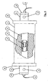
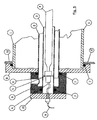
- the radiator assembly is described in detail below with reference to FIGS FIGS. 4 and 5 explained.
- This consists of a centrally arranged, cylindrical UV radiator, such as a Hg-MD radiator with a power of at least 10 watts of UV-C radiation per centimeter in the axial direction, which radiation source 4 is provided with holder 5 and 6 electrical connections.
- Outer cladding tube 1, middle cladding tube 2 and inner cladding tube 3, preferably formed of UV-transparent quartz glass, are arranged concentrically to the UV radiation source 4 and sealed with lateral, sealed with O-rings 7 holders 8, 9 and an end cover 10.
- connections 11 for the coolant circulation of the coolant are provided in the cavity between the inner sheath 3 and the middle sheath 2.
- the more uniform possible distribution of the irradiation intensity on the absorbing liquid according to the invention is illustrated below by way of example with a water throughput of 10,000 m 3 / h corresponding to 2777 1 / sec.
- an irradiance of about 1.2 W / cm 2 is calculated for the outer surface of the cladding tube, an irradiation intensity of about 0.65 W / cm 2 at a distance of 1 cm and an irradiation intensity of about 0 at a distance of 2 cm , 38 W / cm 2 , corresponding to less than a third.
- the irradiation density in the above example at the cladding tube is 0.477 (0.238) W / cm 2 and becomes approximately at a radial distance of 3 cm (3.5 cm) Third, namely 0.153 W / cm 2 (0.08 W / cm 2 ).
- the associated volume per UV source is approx. 12.2 l (26 l) corresponding to 610 l (1300 l) total volume for 50 radiators.
- the enlargement of the outer cladding tube thus allows significantly greater flow rates of the liquid to be irradiated. For this purpose, however, it is necessary to effectively dissipate the heat generated by the powerful UV radiation source by means of the coolant.
- the coolant itself must absorb as little as possible UV radiation, so that a relatively "thin" cavity between inner cladding tube 3 and middle cladding tube 2 is flowed through by the coolant, which is preferably distilled water, possibly due to the low UV absorption with ethanol additive to prevent the formation of bacteria or algae.
- the cladding tubes 1, 2, 3 are preferably formed of quartz glass.
- FIG. 6 shows a substantial homogenization of the irradiation intensity, which is schematically shown in FIG. 6 is shown.
- Fig. 1 shows a number of Hg-MD radiators with a diameter of the outer cladding tube 1 of 20 cm, which have a radiant power of 15 W / cm and a minimum distance of 7 cm between two adjacent radiators corresponding to the pattern of a two-dimensionally closest spherical packing.
- the desirable enlargement of the outer cladding tube 1 requires additional measures to eliminate the thermal energy associated with the operation of the powerful UV source. Since the heat dissipation is no longer sufficient by convection with downstream heat transfer into the medium to be irradiated in the enlarged at a larger sheath tube distances of several centimeters, three quartz tubes 1, 2, 3 are provided for each radiator assembly according to the invention, namely the inner sheath 3, This provides the opportunity to circulate through the cavity between the inner cladding tube 3 and the middle cladding tube 2 fully desalted water or other sufficiently UV trimettis liquid or gaseous cooling medium.
- a significant advantage of the device according to the invention lies in the effective prevention of deposits on the outer cladding tube, which is surrounded by the liquid to be irradiated.
- the entire thermal energy generated in the UV source is delivered via the cladding tube to the liquid to be irradiated. This necessarily leads to a temperature gradient cladding-water.
- particles can be deposited on the outer surface of the cladding tube, in particular at low flow rates, whereby the absorption of the UV, VIS and IR radiation further increase this temperature gradient. This further accelerates the formation of deposits. Eventually, true dark and firm crusts can form that are difficult to remove.
- the deposits form only a thin film on the surface of the cladding tube, which is rinsed off again at full flow.
- the requirements for the heat load per unit area and the tangential velocity can be converted into concrete geometrical requirements based on an example of Hg-MD emitters for wastewater disinfection on the basis of the following exemplary characteristic data: Length of the discharge path: 100 cm UV-C radiation output > 1200W Penetration depth in the water 3 cm (decrease to l / e) required average dose: 40 mJ / cm 2 according to the following formula (1)
- Dissolved by the flow results using a minimum speed of the water of 2 m / sec, a maximum free cross-section of 900 cm 2 per radiator corresponding to a maximum clearance between two adjacent sheaths of 9 cm.
Landscapes
- Health & Medical Sciences (AREA)
- Life Sciences & Earth Sciences (AREA)
- Hydrology & Water Resources (AREA)
- Engineering & Computer Science (AREA)
- General Health & Medical Sciences (AREA)
- Public Health (AREA)
- Veterinary Medicine (AREA)
- Toxicology (AREA)
- Epidemiology (AREA)
- Animal Behavior & Ethology (AREA)
- Environmental & Geological Engineering (AREA)
- Water Supply & Treatment (AREA)
- Chemical & Material Sciences (AREA)
- Organic Chemistry (AREA)
- Physical Water Treatments (AREA)
- Apparatus For Disinfection Or Sterilisation (AREA)
Claims (18)
- Dispositif pour exposer à des rayonnements ultraviolets un liquide absorbant dans un écoulement, présentant au moins deux sous-groupes de génération de rayons ultraviolets ayant chacun une source de rayonnements ultraviolets (4) cylindrique autour de laquelle sont disposés trois tubes de gainage (1, 2, 3) concentriques, un agent réfrigérant s'écoulant entre un tube de gainage intérieur (3) et un tube de gainage médian (2) parmi les tubes de gainage pour dévier la chaleur de la source de rayonnements ultraviolets, le liquide à exposer au rayonnement s'écoulant autour du tube de gainage extérieur (1) parmi les trois tubes de gainage et n'entrant en contact qu'avec celui-ci.
- Dispositif selon la revendication 1, dans lequel un remplissage de gaz est prévu dans la cavité entre le tube de gainage extérieur (1) et le tube de gainage médian (2).
- Dispositif selon la revendication 1 ou 2, dans lequel le diamètre extérieur du tube de gainage extérieur (1) est compris entre 80 et 250 mm.
- Dispositif selon une des revendications 1 à 3, dans lequel la source de rayonnements ultraviolets (4) présente une densité de puissance d'au moins 10 watt de rayonnements ultraviolets C par cm dans la direction axiale.
- Dispositif selon l'une des revendications 1 à 4, dans lequel la source de rayonnements ultraviolets est un générateur de rayons à moyenne pression de mercure.
- Dispositif selon l'une des revendications 1 à 5, dans lequel les sources de rayonnements ultraviolets cylindriques, au moins au nombre de deux, sont disposées à l'horizontale transversalement au sens d'écoulement du liquide absorbant.
- Dispositif selon la revendication 6, dans lequel les sources de rayonnements ultraviolets (4) cylindriques, au moins au nombre de deux, sont mises en place des deux côtés sur une paroi en acier (12) en forme de U munie de perforations (18) circulaires.
- Dispositif selon la revendication 7, dans lequel les deux extrémités des trois tubes de gainage (1, 2, 3) concentriques sont supportées de façon à être étanches vis-à-vis de la paroi en acier (12) en forme de U, des raccordements pour l'énergie électrique et l'agent réfrigérant étant situés au niveau de ces extrémités.
- Dispositif selon l'une des revendications 1 à 8, présentant des couvercles (8, 9, 10) qui empêchent une sortie vers le haut des rayonnements ultraviolets.
- Dispositif selon la revendication 8, présentant au moins une fosse de montage (16, 17) disposée latéralement dans le sens de l'écoulement du liquide absorbant, fosse de montage qui permet la maintenance et le remplacement des sources de rayonnements ultraviolets (4) sans le démontage de pièces en contact avec le liquide.
- Dispositif selon la revendication 6, dans lequel plusieurs sources de rayonnements ultraviolets sont disposées dans la coupe longitudinale selon l'échantillon d'une garniture cylindrique bidimensionnelle extrêmement étanche.
- Dispositif selon l'une des revendications 1 à 11, présentant une pompe de recirculation de réfrigérant (22) ainsi qu'un échangeur de chaleur (23) pour fournir, au courant du liquide à absorber, l'énergie thermique prélevée sur le réfrigérant.
- Dispositif selon la revendication 12, dans lequel l'échangeur de chaleur (23) sert simultanément de blindage contre les rayonnements ultraviolets sortant vers l'avant dans le sens de l'écoulement, et d'obstacle à l'écoulement afin d'homogénéiser le flux de la zone de rayonnement.
- Dispositif selon l'une des revendications 1 à 13, dans lequel de l'eau distillée additionnée d'alcool est utilisée comme agent réfrigérant.
- Dispositif selon l'une des revendications 1 à 14, présentant une régulation, dépendant du débit, de la puissance des sources de rayonnements ultraviolets (4).
- Dispositif selon l'une des revendications 1 à 15, dans lequel le passage libre entre les tubes de gainage extérieurs (1) de deux sources de rayonnements ultraviolets (4) disposées l'une sur l'autre est choisi de sorte que la vitesse tangentielle du liquide sur la surface du tube de gainage extérieur, exprimée en m/s, est plus grande que la valeur numérique de la densité de puissance des rayonnements ultraviolets sortant à travers le tube de gainage extérieur (1), exprimée en W/cm2.
- Dispositif selon l'une des revendications 1 à 16, dans lequel le liquide absorbant est constitué d'eaux usées à désinfecter.
- Installation d'épuration des eaux usées, présentant un dispositif d'exposition aux rayonnements selon l'une des revendications 1 à 17.
Applications Claiming Priority (2)
| Application Number | Priority Date | Filing Date | Title |
|---|---|---|---|
| DE102004058405A DE102004058405B4 (de) | 2004-12-03 | 2004-12-03 | Vorrichtung zur UV-Bestrahlung von absorbierenden Flüssigkeiten im Durchfluss |
| PCT/EP2005/056395 WO2006058909A1 (fr) | 2004-12-03 | 2005-12-02 | Dispositif pour exposer en continu des liquides absorbants a des rayonnements ultraviolets |
Publications (2)
| Publication Number | Publication Date |
|---|---|
| EP1817063A1 EP1817063A1 (fr) | 2007-08-15 |
| EP1817063B1 true EP1817063B1 (fr) | 2009-11-25 |
Family
ID=36118049
Family Applications (1)
| Application Number | Title | Priority Date | Filing Date |
|---|---|---|---|
| EP05850427A Ceased EP1817063B1 (fr) | 2004-12-03 | 2005-12-02 | Dispositif pour exposer en continu des liquides absorbants a des rayonnements ultraviolets |
Country Status (6)
| Country | Link |
|---|---|
| US (1) | US7642522B2 (fr) |
| EP (1) | EP1817063B1 (fr) |
| AT (1) | ATE449616T1 (fr) |
| CA (1) | CA2589100C (fr) |
| DE (2) | DE102004058405B4 (fr) |
| WO (1) | WO2006058909A1 (fr) |
Families Citing this family (17)
| Publication number | Priority date | Publication date | Assignee | Title |
|---|---|---|---|---|
| DE10245103A1 (de) * | 2002-09-27 | 2004-04-08 | General Electric Co. | Schaltschrank für eine Windenergieanlage und Verfahren zum Betreiben einer Windenergieanlage |
| SI1622651T1 (sl) * | 2003-01-21 | 2013-07-31 | Safe Foods Corporation | Modularna, visokovolumna, pod visokim pritiskom tekoča dezinfekcijska UV radiacija |
| DE102004037603B3 (de) * | 2004-08-03 | 2005-10-27 | Atlas Material Testing Technology Gmbh | Regelung der UV-Strahlungsquellen einer Bewitterungsvorrichtung auf der Basis der gemittelten Strahlungsintensität |
| US7586104B2 (en) * | 2007-01-04 | 2009-09-08 | Tae-Hyoung Kim | Non-heating type fluid sterilizing apparatus |
| TWI478875B (zh) * | 2008-01-31 | 2015-04-01 | Solvay | 使水性組成物中之有機物質降解之方法 |
| DE202008008577U1 (de) | 2008-06-25 | 2008-09-18 | Umex Gmbh Dresden | Vorrichtung zur Verhinderung des Strahlungsaustritts bei UV-Bestrahlungsanlagen |
| US20100224562A1 (en) * | 2009-03-05 | 2010-09-09 | Rolchigo Philip M | Ultraviolet Disinfection System and Method |
| DE202009007550U1 (de) | 2009-05-27 | 2009-08-20 | Umex Gmbh Dresden | Vorrichtung zur UV-Bestrahlung |
| KR101012755B1 (ko) * | 2010-06-11 | 2011-02-08 | 주식회사 파나시아 | 수밀기능을 가진 자외선 살균장치 |
| DE102010042670B4 (de) | 2010-10-20 | 2013-07-18 | Umex Gmbh Dresden | Vorrichtung zur UV-Bestrahlung |
| US9169134B2 (en) * | 2013-04-08 | 2015-10-27 | Eaton Corporation | Sealing about a quartz tube |
| HUE035031T2 (en) * | 2014-07-11 | 2018-05-02 | Vicente Fidel Salas | System and method for sterilizing a fluid |
| CN210012631U (zh) * | 2018-10-31 | 2020-02-04 | 厦门百霖净水科技有限公司 | 一种带uv灯的过滤装置 |
| US11007292B1 (en) | 2020-05-01 | 2021-05-18 | Uv Innovators, Llc | Automatic power compensation in ultraviolet (UV) light emission device, and related methods of use, particularly suited for decontamination |
| DE202023100378U1 (de) | 2023-01-27 | 2023-03-02 | TISMA Maschinenbau e. K. | Vorrichtung zur Verhinderung eines Strahlungsaustritts bei UV Reaktoren |
| FR3147269A1 (fr) * | 2023-04-02 | 2024-10-04 | Enthal.P | Dispositif de traitement d’un fluide par rayonnement ultraviolet |
| GB202305430D0 (en) * | 2023-04-13 | 2023-05-31 | Snowball Malcolm Robert | UV split conveyor |
Family Cites Families (9)
| Publication number | Priority date | Publication date | Assignee | Title |
|---|---|---|---|---|
| US4968489A (en) | 1988-09-13 | 1990-11-06 | Peroxidation Systems, Inc. | UV lamp enclosure sleeve |
| US5124131A (en) * | 1990-12-10 | 1992-06-23 | Ultraviolet Energy Generators, Inc. | Compact high-throughput ultraviolet processing chamber |
| US5505912A (en) * | 1992-02-18 | 1996-04-09 | Cryptonics Corporation | Lamp cooling for a UV lamp reactor assembly |
| DE4438052C2 (de) * | 1994-10-25 | 1998-07-16 | Guenther O Prof Dr Schenck | Verfahren, Vorrichtung und Strahlungsquelle zur oxidativen Photopurifikation |
| FR2729382B1 (fr) * | 1995-01-16 | 1997-03-28 | Omnium Traitement Valorisa | Reacteur d'irradiation uv pour le traitement de liquides |
| ATE197285T1 (de) | 1995-08-30 | 2000-11-15 | Uv Systems Technology Inc | Uv-entkeimungssystem für abwasser |
| US20020145875A1 (en) * | 2001-04-10 | 2002-10-10 | Perkinelmer Optoelectronics N.C., Inc. | Compact water-cooled multi-kilowatt lamp |
| DE10129178A1 (de) * | 2001-06-19 | 2003-01-02 | Wedeco Ag | UV-Bestrahlungsvorrichtung für die Behandlung von Fluiden mit einer vereinfachten Bestrahlungskammer |
| US7030391B2 (en) * | 2004-06-04 | 2006-04-18 | Cfm Corporation | Ultraviolet sterilization device |
-
2004
- 2004-12-03 DE DE102004058405A patent/DE102004058405B4/de not_active Expired - Fee Related
-
2005
- 2005-12-02 AT AT05850427T patent/ATE449616T1/de not_active IP Right Cessation
- 2005-12-02 US US11/720,297 patent/US7642522B2/en not_active Expired - Fee Related
- 2005-12-02 WO PCT/EP2005/056395 patent/WO2006058909A1/fr not_active Ceased
- 2005-12-02 DE DE502005008596T patent/DE502005008596D1/de not_active Expired - Lifetime
- 2005-12-02 EP EP05850427A patent/EP1817063B1/fr not_active Ceased
- 2005-12-02 CA CA2589100A patent/CA2589100C/fr not_active Expired - Fee Related
Also Published As
| Publication number | Publication date |
|---|---|
| DE502005008596D1 (de) | 2010-01-07 |
| CA2589100C (fr) | 2012-08-21 |
| EP1817063A1 (fr) | 2007-08-15 |
| ATE449616T1 (de) | 2009-12-15 |
| DE102004058405B4 (de) | 2008-03-13 |
| WO2006058909A1 (fr) | 2006-06-08 |
| US7642522B2 (en) | 2010-01-05 |
| DE102004058405A1 (de) | 2006-06-22 |
| CA2589100A1 (fr) | 2006-06-08 |
| US20080210884A1 (en) | 2008-09-04 |
Similar Documents
| Publication | Publication Date | Title |
|---|---|---|
| EP1817063B1 (fr) | Dispositif pour exposer en continu des liquides absorbants a des rayonnements ultraviolets | |
| EP1144314B1 (fr) | Dispositif d'exposition aux rayons ultraviolets, notamment pour desinfecter des liquides a transmission d'ultraviolets reduite | |
| DE69823106T2 (de) | Vorrichtung zur Erhöhung der in Flüssigkeiten eingebrachten UV-Strahlungsmenge in UV-Desinfektionssystemen mit offenem Strömungskanälen | |
| CN101528611B (zh) | 液体处理系统 | |
| EP0806526A2 (fr) | Dispositif pour la délivrance de l'eau | |
| DE102010014712B3 (de) | Modularer Photo-Röhrenreaktor | |
| DE4417139A1 (de) | Vorrichtung und Anlage zur Desinfektion von strömenden Flüssigkeiten | |
| DE102020108265A1 (de) | Vorrichtung zum Desinfizieren eines Fluids | |
| DE102010042670B4 (de) | Vorrichtung zur UV-Bestrahlung | |
| EP2952824A1 (fr) | Dispositif et procédé destinés à la distillation solaire | |
| DE19619022C2 (de) | Wassertankanordnung | |
| EP3678790B1 (fr) | Tunnel d'irradiation pour des récipients et procédé d'irradiation de récipients | |
| EP0705220B1 (fr) | Procede et dispositif permettant d'optimiser l'intensite du rayonnement dirige sur des eaux d'egout et des eaux usees a irradier | |
| DE29614998U1 (de) | Wasserentnahmearmatur | |
| DE102011111367B4 (de) | Anlage zur Entkeimung oder Aufbereitung einer Flüssigkeit mittels UVC-Strahlung sowie dafür geeignetes Strahlermodul | |
| EP0622337B1 (fr) | Dispositif pour le traitement des eaux chargées avec microorganismes, en particulier des agents du genre Legionella avec rayons ultra-violets | |
| DE4134711A1 (de) | Vorrichtung zur entkeimung von fluessigkeiten durch bestrahlung | |
| DE60320563T2 (de) | Verfahren und vorrichtung zur entkeimung von abwasser und oxidativen inaktivierung der darin enthaltenen inhaltsstoffe | |
| US20250162903A1 (en) | Mounting structures for open channel uv water treatment installations | |
| DE102010007168A1 (de) | Bioreaktor zur Vermehrung von Mikroorganismen | |
| DE1911377C3 (de) | Anlage zur Behandlung von Abwasser | |
| DE725684C (de) | Einrichtung zur Behandlung von Fluessigkeiten durch Ultraviolettstrahlen | |
| DE202007000031U1 (de) | Vorrichtung zur Wasserdesinfektion bzw. Entkeimung von Wasser durch Behandlung mit ultravioletter (UV-)Strahlung | |
| DE2927015A1 (de) | Vorrichtung zum steuern eines in einem fluessigmistbehaelter ablaufenden mikrobiologischen umsetzungsprozesses | |
| DE8401717U1 (de) | Vorrichtung zur schmutzwasserklaerung mit waermerueckgewinnung |
Legal Events
| Date | Code | Title | Description |
|---|---|---|---|
| PUAI | Public reference made under article 153(3) epc to a published international application that has entered the european phase |
Free format text: ORIGINAL CODE: 0009012 |
|
| 17P | Request for examination filed |
Effective date: 20070626 |
|
| AK | Designated contracting states |
Kind code of ref document: A1 Designated state(s): AT BE BG CH CY CZ DE DK EE ES FI FR GB GR HU IE IS IT LI LT LU LV MC NL PL PT RO SE SI SK TR |
|
| 17Q | First examination report despatched |
Effective date: 20070914 |
|
| DAX | Request for extension of the european patent (deleted) | ||
| GRAP | Despatch of communication of intention to grant a patent |
Free format text: ORIGINAL CODE: EPIDOSNIGR1 |
|
| GRAS | Grant fee paid |
Free format text: ORIGINAL CODE: EPIDOSNIGR3 |
|
| GRAA | (expected) grant |
Free format text: ORIGINAL CODE: 0009210 |
|
| AK | Designated contracting states |
Kind code of ref document: B1 Designated state(s): AT BE BG CH CY CZ DE DK EE ES FI FR GB GR HU IE IS IT LI LT LU LV MC NL PL PT RO SE SI SK TR |
|
| REG | Reference to a national code |
Ref country code: GB Ref legal event code: FG4D Free format text: NOT ENGLISH |
|
| REG | Reference to a national code |
Ref country code: CH Ref legal event code: EP |
|
| REG | Reference to a national code |
Ref country code: IE Ref legal event code: FG4D |
|
| REF | Corresponds to: |
Ref document number: 502005008596 Country of ref document: DE Date of ref document: 20100107 Kind code of ref document: P |
|
| REG | Reference to a national code |
Ref country code: NL Ref legal event code: VDEP Effective date: 20091125 |
|
| LTIE | Lt: invalidation of european patent or patent extension |
Effective date: 20091125 |
|
| PG25 | Lapsed in a contracting state [announced via postgrant information from national office to epo] |
Ref country code: LT Free format text: LAPSE BECAUSE OF FAILURE TO SUBMIT A TRANSLATION OF THE DESCRIPTION OR TO PAY THE FEE WITHIN THE PRESCRIBED TIME-LIMIT Effective date: 20091125 Ref country code: IS Free format text: LAPSE BECAUSE OF FAILURE TO SUBMIT A TRANSLATION OF THE DESCRIPTION OR TO PAY THE FEE WITHIN THE PRESCRIBED TIME-LIMIT Effective date: 20100325 Ref country code: FI Free format text: LAPSE BECAUSE OF FAILURE TO SUBMIT A TRANSLATION OF THE DESCRIPTION OR TO PAY THE FEE WITHIN THE PRESCRIBED TIME-LIMIT Effective date: 20091125 Ref country code: SE Free format text: LAPSE BECAUSE OF FAILURE TO SUBMIT A TRANSLATION OF THE DESCRIPTION OR TO PAY THE FEE WITHIN THE PRESCRIBED TIME-LIMIT Effective date: 20091125 Ref country code: PT Free format text: LAPSE BECAUSE OF FAILURE TO SUBMIT A TRANSLATION OF THE DESCRIPTION OR TO PAY THE FEE WITHIN THE PRESCRIBED TIME-LIMIT Effective date: 20100325 |
|
| PG25 | Lapsed in a contracting state [announced via postgrant information from national office to epo] |
Ref country code: CY Free format text: LAPSE BECAUSE OF FAILURE TO SUBMIT A TRANSLATION OF THE DESCRIPTION OR TO PAY THE FEE WITHIN THE PRESCRIBED TIME-LIMIT Effective date: 20091125 Ref country code: SI Free format text: LAPSE BECAUSE OF FAILURE TO SUBMIT A TRANSLATION OF THE DESCRIPTION OR TO PAY THE FEE WITHIN THE PRESCRIBED TIME-LIMIT Effective date: 20091125 Ref country code: PL Free format text: LAPSE BECAUSE OF FAILURE TO SUBMIT A TRANSLATION OF THE DESCRIPTION OR TO PAY THE FEE WITHIN THE PRESCRIBED TIME-LIMIT Effective date: 20091125 Ref country code: LV Free format text: LAPSE BECAUSE OF FAILURE TO SUBMIT A TRANSLATION OF THE DESCRIPTION OR TO PAY THE FEE WITHIN THE PRESCRIBED TIME-LIMIT Effective date: 20091125 |
|
| REG | Reference to a national code |
Ref country code: IE Ref legal event code: FD4D |
|
| BERE | Be: lapsed |
Owner name: DELTA UV SERVICE SYSTEME Effective date: 20091231 |
|
| PG25 | Lapsed in a contracting state [announced via postgrant information from national office to epo] |
Ref country code: MC Free format text: LAPSE BECAUSE OF NON-PAYMENT OF DUE FEES Effective date: 20100701 Ref country code: ES Free format text: LAPSE BECAUSE OF FAILURE TO SUBMIT A TRANSLATION OF THE DESCRIPTION OR TO PAY THE FEE WITHIN THE PRESCRIBED TIME-LIMIT Effective date: 20100308 Ref country code: DK Free format text: LAPSE BECAUSE OF FAILURE TO SUBMIT A TRANSLATION OF THE DESCRIPTION OR TO PAY THE FEE WITHIN THE PRESCRIBED TIME-LIMIT Effective date: 20091125 Ref country code: BG Free format text: LAPSE BECAUSE OF FAILURE TO SUBMIT A TRANSLATION OF THE DESCRIPTION OR TO PAY THE FEE WITHIN THE PRESCRIBED TIME-LIMIT Effective date: 20100225 Ref country code: EE Free format text: LAPSE BECAUSE OF FAILURE TO SUBMIT A TRANSLATION OF THE DESCRIPTION OR TO PAY THE FEE WITHIN THE PRESCRIBED TIME-LIMIT Effective date: 20091125 Ref country code: RO Free format text: LAPSE BECAUSE OF FAILURE TO SUBMIT A TRANSLATION OF THE DESCRIPTION OR TO PAY THE FEE WITHIN THE PRESCRIBED TIME-LIMIT Effective date: 20091125 Ref country code: IE Free format text: LAPSE BECAUSE OF FAILURE TO SUBMIT A TRANSLATION OF THE DESCRIPTION OR TO PAY THE FEE WITHIN THE PRESCRIBED TIME-LIMIT Effective date: 20091125 Ref country code: NL Free format text: LAPSE BECAUSE OF FAILURE TO SUBMIT A TRANSLATION OF THE DESCRIPTION OR TO PAY THE FEE WITHIN THE PRESCRIBED TIME-LIMIT Effective date: 20091125 |
|
| REG | Reference to a national code |
Ref country code: CH Ref legal event code: PL |
|
| PG25 | Lapsed in a contracting state [announced via postgrant information from national office to epo] |
Ref country code: SK Free format text: LAPSE BECAUSE OF FAILURE TO SUBMIT A TRANSLATION OF THE DESCRIPTION OR TO PAY THE FEE WITHIN THE PRESCRIBED TIME-LIMIT Effective date: 20091125 Ref country code: CZ Free format text: LAPSE BECAUSE OF FAILURE TO SUBMIT A TRANSLATION OF THE DESCRIPTION OR TO PAY THE FEE WITHIN THE PRESCRIBED TIME-LIMIT Effective date: 20091125 |
|
| PLBE | No opposition filed within time limit |
Free format text: ORIGINAL CODE: 0009261 |
|
| STAA | Information on the status of an ep patent application or granted ep patent |
Free format text: STATUS: NO OPPOSITION FILED WITHIN TIME LIMIT |
|
| PG25 | Lapsed in a contracting state [announced via postgrant information from national office to epo] |
Ref country code: BE Free format text: LAPSE BECAUSE OF NON-PAYMENT OF DUE FEES Effective date: 20091231 Ref country code: CH Free format text: LAPSE BECAUSE OF NON-PAYMENT OF DUE FEES Effective date: 20091231 Ref country code: GR Free format text: LAPSE BECAUSE OF FAILURE TO SUBMIT A TRANSLATION OF THE DESCRIPTION OR TO PAY THE FEE WITHIN THE PRESCRIBED TIME-LIMIT Effective date: 20100226 Ref country code: LI Free format text: LAPSE BECAUSE OF NON-PAYMENT OF DUE FEES Effective date: 20091231 |
|
| 26N | No opposition filed |
Effective date: 20100826 |
|
| PG25 | Lapsed in a contracting state [announced via postgrant information from national office to epo] |
Ref country code: IT Free format text: LAPSE BECAUSE OF FAILURE TO SUBMIT A TRANSLATION OF THE DESCRIPTION OR TO PAY THE FEE WITHIN THE PRESCRIBED TIME-LIMIT Effective date: 20091125 |
|
| PG25 | Lapsed in a contracting state [announced via postgrant information from national office to epo] |
Ref country code: LU Free format text: LAPSE BECAUSE OF NON-PAYMENT OF DUE FEES Effective date: 20091202 |
|
| PG25 | Lapsed in a contracting state [announced via postgrant information from national office to epo] |
Ref country code: AT Free format text: LAPSE BECAUSE OF NON-PAYMENT OF DUE FEES Effective date: 20091202 |
|
| PG25 | Lapsed in a contracting state [announced via postgrant information from national office to epo] |
Ref country code: HU Free format text: LAPSE BECAUSE OF FAILURE TO SUBMIT A TRANSLATION OF THE DESCRIPTION OR TO PAY THE FEE WITHIN THE PRESCRIBED TIME-LIMIT Effective date: 20100526 |
|
| PG25 | Lapsed in a contracting state [announced via postgrant information from national office to epo] |
Ref country code: TR Free format text: LAPSE BECAUSE OF FAILURE TO SUBMIT A TRANSLATION OF THE DESCRIPTION OR TO PAY THE FEE WITHIN THE PRESCRIBED TIME-LIMIT Effective date: 20091125 |
|
| REG | Reference to a national code |
Ref country code: FR Ref legal event code: PLFP Year of fee payment: 11 |
|
| REG | Reference to a national code |
Ref country code: FR Ref legal event code: PLFP Year of fee payment: 12 |
|
| REG | Reference to a national code |
Ref country code: FR Ref legal event code: PLFP Year of fee payment: 13 |
|
| PGFP | Annual fee paid to national office [announced via postgrant information from national office to epo] |
Ref country code: FR Payment date: 20171219 Year of fee payment: 13 |
|
| PGFP | Annual fee paid to national office [announced via postgrant information from national office to epo] |
Ref country code: GB Payment date: 20171221 Year of fee payment: 13 |
|
| PGFP | Annual fee paid to national office [announced via postgrant information from national office to epo] |
Ref country code: DE Payment date: 20171229 Year of fee payment: 13 |
|
| REG | Reference to a national code |
Ref country code: DE Ref legal event code: R119 Ref document number: 502005008596 Country of ref document: DE |
|
| GBPC | Gb: european patent ceased through non-payment of renewal fee |
Effective date: 20181202 |
|
| PG25 | Lapsed in a contracting state [announced via postgrant information from national office to epo] |
Ref country code: DE Free format text: LAPSE BECAUSE OF NON-PAYMENT OF DUE FEES Effective date: 20190702 Ref country code: FR Free format text: LAPSE BECAUSE OF NON-PAYMENT OF DUE FEES Effective date: 20181231 |
|
| PG25 | Lapsed in a contracting state [announced via postgrant information from national office to epo] |
Ref country code: GB Free format text: LAPSE BECAUSE OF NON-PAYMENT OF DUE FEES Effective date: 20181202 |