EP1817123B1 - Gerät und verfahren zur ausrichtung der zuführvorrichtungen und der kanäle in einem walzgerüst - Google Patents
Gerät und verfahren zur ausrichtung der zuführvorrichtungen und der kanäle in einem walzgerüst Download PDFInfo
- Publication number
- EP1817123B1 EP1817123B1 EP05805660A EP05805660A EP1817123B1 EP 1817123 B1 EP1817123 B1 EP 1817123B1 EP 05805660 A EP05805660 A EP 05805660A EP 05805660 A EP05805660 A EP 05805660A EP 1817123 B1 EP1817123 B1 EP 1817123B1
- Authority
- EP
- European Patent Office
- Prior art keywords
- rolling stand
- input
- slide
- rays
- groove
- Prior art date
- Legal status (The legal status is an assumption and is not a legal conclusion. Google has not performed a legal analysis and makes no representation as to the accuracy of the status listed.)
- Expired - Lifetime
Links
Images




Classifications
-
- B—PERFORMING OPERATIONS; TRANSPORTING
- B21—MECHANICAL METAL-WORKING WITHOUT ESSENTIALLY REMOVING MATERIAL; PUNCHING METAL
- B21B—ROLLING OF METAL
- B21B38/00—Methods or devices for measuring, detecting or monitoring specially adapted for metal-rolling mills, e.g. position detection, inspection of the product
- B21B38/10—Methods or devices for measuring, detecting or monitoring specially adapted for metal-rolling mills, e.g. position detection, inspection of the product for measuring roll-gap, e.g. pass indicators
- B21B38/105—Calibrating or presetting roll-gap
-
- B—PERFORMING OPERATIONS; TRANSPORTING
- B21—MECHANICAL METAL-WORKING WITHOUT ESSENTIALLY REMOVING MATERIAL; PUNCHING METAL
- B21B—ROLLING OF METAL
- B21B39/00—Arrangements for moving, supporting, or positioning work, or controlling its movement, combined with or arranged in, or specially adapted for use in connection with, metal-rolling mills
- B21B39/14—Guiding, positioning or aligning work
- B21B39/16—Guiding, positioning or aligning work immediately before entering or after leaving the pass
- B21B39/165—Guides or guide rollers for rods, bars, rounds, tubes ; Aligning guides
-
- B—PERFORMING OPERATIONS; TRANSPORTING
- B21—MECHANICAL METAL-WORKING WITHOUT ESSENTIALLY REMOVING MATERIAL; PUNCHING METAL
- B21B—ROLLING OF METAL
- B21B1/00—Metal-rolling methods or mills for making semi-finished products of solid or profiled cross-section; Sequence of operations in milling trains; Layout of rolling-mill plant, e.g. grouping of stands; Succession of passes or of sectional pass alternations
- B21B1/16—Metal-rolling methods or mills for making semi-finished products of solid or profiled cross-section; Sequence of operations in milling trains; Layout of rolling-mill plant, e.g. grouping of stands; Succession of passes or of sectional pass alternations for rolling wire rods, bars, merchant bars, rounds wire or material of like small cross-section
Definitions
- the present invention refers to a device and method for aligning the input apparatuses and the channels in the rolling stands.
- a device according to the preamble of claim 1 is e.g. known from DE-A 26 15 069 .
- Rolling plants for long products for example round bars for different uses, comprise a series of rolling stands, arranged in sequence.
- a stand in front view and a detail thereof are respectively schematised.
- Each stand 1 is equipped with two rolling cylinders or rollers 2, 3, one top one bottom, on which the channels 4 are formed.
- the rolled material passing through the aforementioned channels 4 is deformed according to the profile of the channel itself.
- the channel is formed in two half-grooves 4' and 4", the first of which is formed in the top roller 2 and the second in the bottom roller 3.
- the system comprising the rolling stand complete with grooved rollers and the relative input apparatuses is foreseen to make, at the output of the stand itself, a rolled material of desired shape and size, and with narrow tolerances.
- the top cylinder is axially adjustable with respect to the bottom cylinder, and the distance between the two cylinders is symmetrically adjustable with respect to the centre of the channel.
- the aforementioned distance must be precalibrated at a precise measurement to take into account the elastic yielding of the machine under the deformation load in order to obtain the required size.
- the input guide apparatus is mounted on a slide held in position by guides at 45° and by a central key.
- the assembly is mounted on a guide support fixed to the structure of the stand.
- the slide can be translated in the longitudinal direction to centre the apparatus in the centre of the channel.
- the general purpose of the present invention is, therefore, that of providing a device that allows an alignment of the grooves forming the passage channel of the rolled material to be obtained.
- Another purpose of the present invention is that of making a device that allows the measurement of the position of the input apparatus-carrying slide with respect to the centre of the rolling channel.
- the last but not least purpose of the present invention is that of providing a method for aligning the input apparatuses and the channels in a rolling stand.
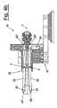
- a device 10 for aligning the input apparatuses and the channels in a rolling stand 1 comprises a measuring instrument 20 comprising a base structure 21 suitable for being mounted on the slide 13, carrying the input apparatus of the rolling stand, through a key in place of the input guide apparatus 5 ( figure 3 ) of the stand.
- the rolling stand to which the device according to the invention is applied, has identical reference numerals for the elements common to the stand according to the prior art according to figures 1-3 .
- the instrument also comprises four shafts 22, each pivoted through a pin F so as to be able to oscillate about said pin.
- Such shafts in operating measurement state are inclined, by an angle ⁇ with respect to the horizontal.
- each shaft 22 carries a push rod 23 suitable for making contact with the surface of one of the grooves 4' or 4" that constitute the rolling channel 4.
- the push rod 23 detects the position of the surface of the groove.
- each shaft actuates an electronic sensor 24 that, through a suitable calculation algorithm, provides the value of the position of each surface with respect to the centre of the instrument.
- the four shafts 22 can each oscillate independently about its pivot F, so as to carry out independent measurements of the position of the groove surface 4', 4 " to be controlled with respect to the centre of the instrument.
- the shafts 22 in practice behave like levers, which can be of the first, second or third type.
- the centring method therefore foresees the steps of:
- An inspection table 30 allows the necessary calibrations for zeroing the measurement instruments to be carried out, being equipped with an upright 31 with a calibration channel 32.
Landscapes
- Engineering & Computer Science (AREA)
- Mechanical Engineering (AREA)
- Length-Measuring Devices Using Wave Or Particle Radiation (AREA)
- Metal Rolling (AREA)
- Length Measuring Devices With Unspecified Measuring Means (AREA)
- A Measuring Device Byusing Mechanical Method (AREA)
- Continuous Casting (AREA)
- Special Chairs (AREA)
- Attitude Control For Articles On Conveyors (AREA)
- Load-Engaging Elements For Cranes (AREA)
- Stacking Of Articles And Auxiliary Devices (AREA)
Claims (5)
- Gerät zur Ausrichtung der Zuführvorrichtungen und der Kanäle in einem Walzgerüst, welches folgendes umfasst: ein Messinstrument (20), das mit Mitteln (22, F, 23) zum Erkennen der Lage der Oberflächen der Kanäle (4) ausgestattet ist, mindestens einen elektronischen Sensor (24), der geeignet ist, derartige Lageerkennungsinformationen zu empfangen, und Instrumentenausrüstung, um die Erkennungsinformationen anzuzeigen und zu verarbeiten, und die erkannte Lage bereitzustellen, dadurch gekennzeichnet, dass die besagten Mittel zur Erkennung der Lage vier schräg stehende Wellen (22) sind, die jeweils durch einen Zapfen (F) drehbar gelagert sind, damit sie sich um den besagten Zapfen vor und zurück bewegen können, ein Ende (22') jeder Welle (22) eine Schubstange (23) trägt, die dafür geeignet ist, den Kontakt zu einer Oberfläche einer der Rillen (4', 4") herzustellen, die den Kanal (4) bilden, um die Lage der Oberfläche der Rille in Bezug auf eine Mittelachse (X) des Messinstruments (20) festzustellen.
- Gerät gemäß Anspruch 1, dadurch gekennzeichnet, dass die besagten vier Wellen (22) derart angeordnet sind, dass sie sich jeweils unabhängig um ihren Zapfen (F) vor und zurück bewegen, um unabhängige Messungen der Lage der Rillenoberfläche (4', 4") auszuführen.
- Gerät gemäß Anspruch 1, dadurch gekennzeichnet, dass das besagte Gerät eine Grundstruktur (21) umfasst, die dafür geeignet ist, durch einen Schlüssel an der Stelle der Zuführvorrichtung des Walzgerüsts auf den Schlitten (13) montiert zu werden, der die Zuführvorrichtungen des Walzgerüsts trägt.
- Gerät gemäß Anspruch 3, dadurch gekennzeichnet, dass das besagte Gerät eine Handkurbel (15) umfasst, die dafür geeignet ist, den Schlitten (13) entlang einer den Schlitten tragenden Basis (16) zu verfahren, wobei die letztere höhenverstellbar vorgesehen ist.
- Verfahren zur Ausrichtung der Zuführvorrichtungen und der Kanäle in einem Walzgerüst, dadurch gekennzeichnet, dass es die folgenden Schritte vorsieht:a) Anordnen und Montieren des Geräts (10) gemäß einem der vorstehenden Ansprüche anstelle der Zuführvorrichtung zum Walzgerüst, wobei das Gerät (10) eine Grundstruktur (21) umfasst, die dafür geeignet ist, durch einen Schlüssel an der Stelle der Zuführvorrichtungen des Walzgerüsts auf den Schlitten (13) montiert zu werden, der die Zuführvorrichtungen des Walzgerüsts trägt;b) weites öffnen der Wellen, bis die Schubstangen (23) mit den Oberflächen der Rillen (4' und 4") in Kontakt kommen;c) Erkennen der vier Strahlen (R1-R4) zwischen den Oberflächen der Rillen (4' und 4") und der mittleren Erkennungsachse (X) des Messinstruments, wobei die Strahlen (R1, R2) sich auf die obere Rille (4') beziehen bzw. die Strahlen (R3, R4) sich auf die untere Rille (4") des Kanals (4) beziehen;d) Kontrollieren der Gleichheit zwischen den Strahlen (R3) und (R4);e) Verschieben des Schlittens (13) durch Betätigen der Handkurbel (15), bis (R3) gleich (R4) ist, falls (R3) von (R4) abweicht, in der Weise, dass der Zentrierschlüssel der Zuführvorrichtung des Walzgerüsts optimal an der Nut (4") der unteren Walze (3) zentriert ist;f) Kontrollieren der Gleichheit zwischen (R1) und (R2);g) Verschieben der oberen Walze (2) mithilfe geeigneter Mechanismen des Walzgerüsts, um die obere Rille mit der unteren Rille zu zentrieren, falls (R2) von (R1) abweicht;h) Überprüfen, ob die Öffnung (H) den in den Walzbedingungen vorgesehenen Wert hat, wobei die besagte Öffnung (H) anhand geometrischer Beziehungen berechnet wird, indem die Strahlen (R1-R4) im Verhältnis zu dem Strahl des bekannten Kanals gelesen werden;i) Fortfahren mit der Justage der beiden Walzen (2, 3), wenn Abweichungen der Werte festgestellt werden;l) Justieren der Höhe der den Schlitten tragenden Basis (16), falls die Werte der Strahlen (R1, R4) bzw. (R2, R3) nicht jeweils gleich sind;m) Ausbauen des Geräts (10);n) Wiedereinbauen der Zuführvorrichtung in das Walzgerüst.
Applications Claiming Priority (2)
| Application Number | Priority Date | Filing Date | Title |
|---|---|---|---|
| IT002060A ITMI20042060A1 (it) | 2004-10-29 | 2004-10-29 | Dispositivo e metodo per l'allineamento delle attrezzature di ingresso e dei canali in una gabbia di laminazione |
| PCT/EP2005/011633 WO2006045629A1 (en) | 2004-10-29 | 2005-10-28 | Device and method for aligning the input apparatuses and the channels in a rolling stand |
Publications (2)
| Publication Number | Publication Date |
|---|---|
| EP1817123A1 EP1817123A1 (de) | 2007-08-15 |
| EP1817123B1 true EP1817123B1 (de) | 2009-12-02 |
Family
ID=35462465
Family Applications (1)
| Application Number | Title | Priority Date | Filing Date |
|---|---|---|---|
| EP05805660A Expired - Lifetime EP1817123B1 (de) | 2004-10-29 | 2005-10-28 | Gerät und verfahren zur ausrichtung der zuführvorrichtungen und der kanäle in einem walzgerüst |
Country Status (10)
| Country | Link |
|---|---|
| US (1) | US7832241B2 (de) |
| EP (1) | EP1817123B1 (de) |
| CN (1) | CN101052480B (de) |
| AT (1) | ATE450325T1 (de) |
| BR (1) | BRPI0517001B1 (de) |
| DE (1) | DE602005018096D1 (de) |
| ES (1) | ES2335789T3 (de) |
| IT (1) | ITMI20042060A1 (de) |
| RU (1) | RU2389574C2 (de) |
| WO (1) | WO2006045629A1 (de) |
Families Citing this family (14)
| Publication number | Priority date | Publication date | Assignee | Title |
|---|---|---|---|---|
| CN104690095A (zh) * | 2015-03-26 | 2015-06-10 | 辽宁天丰特殊工具制造股份有限公司 | 在线连轧辊孔型错位检测仪及检测方法 |
| US10399082B1 (en) | 2015-08-10 | 2019-09-03 | Alex Pearson | Roll adjustment system |
| US10928179B1 (en) * | 2015-08-10 | 2021-02-23 | Pearson Incorporated | Roll adjustment system |
| US9919315B2 (en) * | 2015-08-10 | 2018-03-20 | Pearson Incorporated | Roll adjustment system |
| US10913071B2 (en) | 2016-03-09 | 2021-02-09 | Pearson Incorporated | Scalper apparatus and processing system |
| US10322487B1 (en) | 2016-07-15 | 2019-06-18 | Pearson Incorporated | Roller mill grinding apparatus with regenerative capability |
| US10807098B1 (en) | 2017-07-26 | 2020-10-20 | Pearson Incorporated | Systems and methods for step grinding |
| US11325133B1 (en) | 2018-07-26 | 2022-05-10 | Pearson Incorporated | Systems and methods for monitoring the roll diameter and shock loads in a milling apparatus |
| US10751722B1 (en) | 2018-10-24 | 2020-08-25 | Pearson Incorporated | System for processing cannabis crop materials |
| US10785906B2 (en) | 2019-02-19 | 2020-09-29 | Pearson Incorporated | Plant processing system |
| US10757860B1 (en) | 2019-10-31 | 2020-09-01 | Hemp Processing Solutions, LLC | Stripper apparatus crop harvesting system |
| US10933424B1 (en) | 2019-12-11 | 2021-03-02 | Pearson Incorporated | Grinding roll improvements |
| CN111024002B (zh) * | 2019-12-30 | 2021-04-20 | 新疆八一钢铁股份有限公司 | 一种采用激光红外水平仪检测立辊对中度的方法 |
| CN113976636B (zh) * | 2021-11-01 | 2024-04-16 | 沁阳市宏达钢铁有限公司 | 一种热轧螺纹钢的生产装置及方法 |
Family Cites Families (12)
| Publication number | Priority date | Publication date | Assignee | Title |
|---|---|---|---|---|
| US2368129A (en) * | 1943-04-27 | 1945-01-30 | Morgan Construction Co | Gauge |
| DE1752947A1 (de) * | 1968-08-10 | 1971-04-15 | Moeller & Neumann Gmbh | Messeinrichtung zur Erfassung des Walzspaltes |
| SE371757B (de) | 1972-02-07 | 1974-12-02 | Morgaardshammar Ab | |
| GB1507987A (en) * | 1974-07-15 | 1978-04-19 | British Steel Corp | Mill stand roll parameter monitor |
| GB1508213A (en) * | 1975-04-08 | 1978-04-19 | British Steel Corp | Rolling mill equipment |
| US4171577A (en) * | 1975-07-09 | 1979-10-23 | Vereinigte Flugtechnische Werke-Fokker Gmbh | Gap width measurement for rolling mills |
| US4131004A (en) * | 1977-09-14 | 1978-12-26 | Blaw-Knox Foundry & Mill Machinery, Inc. | Rolling mill gauge and flatness calibration system |
| GB2022286B (en) | 1978-05-12 | 1982-08-04 | Jackson J C | Alignment of guides in rod and bar mills |
| DE3619412A1 (de) * | 1986-06-12 | 1987-12-17 | Hoesch Stahl Ag | Verfahren und vorrichtung zur walzspaltmessung und regelung |
| CH688180A5 (de) * | 1991-02-01 | 1997-06-13 | Pechiney Rhenalu | Messeinrichtung zur Walzspaltregelung. |
| JP2000035669A (ja) | 1998-07-17 | 2000-02-02 | Fuji Photo Film Co Ltd | ネガ型画像記録材料 |
| JP3873505B2 (ja) * | 1999-02-19 | 2007-01-24 | Jfeスチール株式会社 | 条鋼用圧延ロールのロール位置調整方法及びロール位置調整用ガイダンス装置 |
-
2004
- 2004-10-29 IT IT002060A patent/ITMI20042060A1/it unknown
-
2005
- 2005-10-28 US US11/663,785 patent/US7832241B2/en active Active
- 2005-10-28 BR BRPI0517001A patent/BRPI0517001B1/pt not_active IP Right Cessation
- 2005-10-28 WO PCT/EP2005/011633 patent/WO2006045629A1/en not_active Ceased
- 2005-10-28 CN CN2005800374865A patent/CN101052480B/zh not_active Expired - Fee Related
- 2005-10-28 EP EP05805660A patent/EP1817123B1/de not_active Expired - Lifetime
- 2005-10-28 DE DE602005018096T patent/DE602005018096D1/de not_active Expired - Lifetime
- 2005-10-28 ES ES05805660T patent/ES2335789T3/es not_active Expired - Lifetime
- 2005-10-28 AT AT05805660T patent/ATE450325T1/de active
- 2005-10-28 RU RU2007112988/02A patent/RU2389574C2/ru active
Also Published As
| Publication number | Publication date |
|---|---|
| BRPI0517001B1 (pt) | 2018-05-08 |
| CN101052480B (zh) | 2010-12-22 |
| RU2389574C2 (ru) | 2010-05-20 |
| ITMI20042060A1 (it) | 2006-04-30 |
| ATE450325T1 (de) | 2009-12-15 |
| BRPI0517001A (pt) | 2008-09-30 |
| EP1817123A1 (de) | 2007-08-15 |
| US7832241B2 (en) | 2010-11-16 |
| ES2335789T3 (es) | 2010-04-05 |
| HK1107792A1 (en) | 2008-04-18 |
| CN101052480A (zh) | 2007-10-10 |
| US20080053176A1 (en) | 2008-03-06 |
| RU2007112988A (ru) | 2008-12-10 |
| WO2006045629A1 (en) | 2006-05-04 |
| DE602005018096D1 (de) | 2010-01-14 |
Similar Documents
| Publication | Publication Date | Title |
|---|---|---|
| EP1817123B1 (de) | Gerät und verfahren zur ausrichtung der zuführvorrichtungen und der kanäle in einem walzgerüst | |
| RU2602216C2 (ru) | Прокатный стан, а также устройство и способ определения прокатного или направляющего калибра прокатных или направляющих клетей в многоклетевом прокатном стане | |
| CN207963779U (zh) | 一种激光位移传感器校准装置 | |
| CN102162717B (zh) | 滚珠螺母螺旋内滚道综合误差自动检测装置及其方法 | |
| US20170191916A1 (en) | Device for Performing a Bending Test | |
| US20100260380A1 (en) | Device for optically measuring and/or testing oblong products | |
| RU2572058C2 (ru) | Калибровочное устройство для измерительных датчиков, предназначенных для измерения диаметра и других геометрических характеристик цилиндров | |
| US6735878B2 (en) | Method and device for centering a wheel | |
| ITMO20010248A1 (it) | Dilatometro ottico perfezionato | |
| CN117433943A (zh) | 一种基于编码器和微分筒的双向引伸计标定器 | |
| US3834820A (en) | Optical gauge | |
| HK1107792B (en) | Device and method for aligning the input apparatuses and the channels in a rolling stand | |
| US6212960B1 (en) | Apparatus for measuring the flatness of a strip in movement | |
| JPH09229653A (ja) | 管の真円度測定装置 | |
| CN115575096B (zh) | 一种视度倍率检测仪 | |
| CN220251641U (zh) | 维氏硬度计轴承球形滚子硬度检测用工作台 | |
| DE102015119781B4 (de) | Kalibrierverfahren | |
| CN220649452U (zh) | 一种基于高精度测高仪的相机传感器平整度检测装置 | |
| CN115774340B (zh) | 一种大视场可扩展视场仪 | |
| WO2006128445A1 (de) | Extensometer für hohe temperaturen | |
| DE102017131466A1 (de) | Etalon-Stufenwelle und Verfahren zum Kalibrieren optischer Messeinrichtungen | |
| RU60201U1 (ru) | Устройство для измерения расстояния от опорного торца конического зубчатого колеса до точки пересечения образующих наружного и заднего конусов | |
| KR20030053391A (ko) | 열간 압연기의 스크루 축 기울어짐 측정장치 | |
| JP2595862B2 (ja) | 幅測定器の校正装置とこれを用いた補正方法 | |
| JP2982645B2 (ja) | ロールプロフィル測定装置 |
Legal Events
| Date | Code | Title | Description |
|---|---|---|---|
| PUAI | Public reference made under article 153(3) epc to a published international application that has entered the european phase |
Free format text: ORIGINAL CODE: 0009012 |
|
| 17P | Request for examination filed |
Effective date: 20070322 |
|
| AK | Designated contracting states |
Kind code of ref document: A1 Designated state(s): AT BE BG CH CY CZ DE DK EE ES FI FR GB GR HU IE IS IT LI LT LU LV MC NL PL PT RO SE SI SK TR |
|
| 17Q | First examination report despatched |
Effective date: 20071113 |
|
| DAX | Request for extension of the european patent (deleted) | ||
| REG | Reference to a national code |
Ref country code: HK Ref legal event code: DE Ref document number: 1107792 Country of ref document: HK |
|
| GRAP | Despatch of communication of intention to grant a patent |
Free format text: ORIGINAL CODE: EPIDOSNIGR1 |
|
| RAP1 | Party data changed (applicant data changed or rights of an application transferred) |
Owner name: SIEMENS VAI METALS TECHNOLOGIES S.R.L. |
|
| GRAS | Grant fee paid |
Free format text: ORIGINAL CODE: EPIDOSNIGR3 |
|
| GRAA | (expected) grant |
Free format text: ORIGINAL CODE: 0009210 |
|
| AK | Designated contracting states |
Kind code of ref document: B1 Designated state(s): AT BE BG CH CY CZ DE DK EE ES FI FR GB GR HU IE IS IT LI LT LU LV MC NL PL PT RO SE SI SK TR |
|
| REG | Reference to a national code |
Ref country code: GB Ref legal event code: FG4D |
|
| REG | Reference to a national code |
Ref country code: CH Ref legal event code: EP |
|
| REG | Reference to a national code |
Ref country code: IE Ref legal event code: FG4D |
|
| REF | Corresponds to: |
Ref document number: 602005018096 Country of ref document: DE Date of ref document: 20100114 Kind code of ref document: P |
|
| REG | Reference to a national code |
Ref country code: DE Ref legal event code: R096 Ref document number: 602005018096 Country of ref document: DE Effective date: 20100114 |
|
| REG | Reference to a national code |
Ref country code: SE Ref legal event code: TRGR |
|
| REG | Reference to a national code |
Ref country code: ES Ref legal event code: FG2A Ref document number: 2335789 Country of ref document: ES Kind code of ref document: T3 |
|
| REG | Reference to a national code |
Ref country code: NL Ref legal event code: VDEP Effective date: 20091202 |
|
| REG | Reference to a national code |
Ref country code: HK Ref legal event code: GR Ref document number: 1107792 Country of ref document: HK |
|
| PG25 | Lapsed in a contracting state [announced via postgrant information from national office to epo] |
Ref country code: FI Free format text: LAPSE BECAUSE OF FAILURE TO SUBMIT A TRANSLATION OF THE DESCRIPTION OR TO PAY THE FEE WITHIN THE PRESCRIBED TIME-LIMIT Effective date: 20091202 Ref country code: LT Free format text: LAPSE BECAUSE OF FAILURE TO SUBMIT A TRANSLATION OF THE DESCRIPTION OR TO PAY THE FEE WITHIN THE PRESCRIBED TIME-LIMIT Effective date: 20091202 |
|
| LTIE | Lt: invalidation of european patent or patent extension |
Effective date: 20091202 |
|
| PG25 | Lapsed in a contracting state [announced via postgrant information from national office to epo] |
Ref country code: SI Free format text: LAPSE BECAUSE OF FAILURE TO SUBMIT A TRANSLATION OF THE DESCRIPTION OR TO PAY THE FEE WITHIN THE PRESCRIBED TIME-LIMIT Effective date: 20091202 Ref country code: PL Free format text: LAPSE BECAUSE OF FAILURE TO SUBMIT A TRANSLATION OF THE DESCRIPTION OR TO PAY THE FEE WITHIN THE PRESCRIBED TIME-LIMIT Effective date: 20091202 Ref country code: LV Free format text: LAPSE BECAUSE OF FAILURE TO SUBMIT A TRANSLATION OF THE DESCRIPTION OR TO PAY THE FEE WITHIN THE PRESCRIBED TIME-LIMIT Effective date: 20091202 Ref country code: CY Free format text: LAPSE BECAUSE OF FAILURE TO SUBMIT A TRANSLATION OF THE DESCRIPTION OR TO PAY THE FEE WITHIN THE PRESCRIBED TIME-LIMIT Effective date: 20091202 |
|
| PG25 | Lapsed in a contracting state [announced via postgrant information from national office to epo] |
Ref country code: RO Free format text: LAPSE BECAUSE OF FAILURE TO SUBMIT A TRANSLATION OF THE DESCRIPTION OR TO PAY THE FEE WITHIN THE PRESCRIBED TIME-LIMIT Effective date: 20091202 Ref country code: NL Free format text: LAPSE BECAUSE OF FAILURE TO SUBMIT A TRANSLATION OF THE DESCRIPTION OR TO PAY THE FEE WITHIN THE PRESCRIBED TIME-LIMIT Effective date: 20091202 Ref country code: IS Free format text: LAPSE BECAUSE OF FAILURE TO SUBMIT A TRANSLATION OF THE DESCRIPTION OR TO PAY THE FEE WITHIN THE PRESCRIBED TIME-LIMIT Effective date: 20100402 Ref country code: EE Free format text: LAPSE BECAUSE OF FAILURE TO SUBMIT A TRANSLATION OF THE DESCRIPTION OR TO PAY THE FEE WITHIN THE PRESCRIBED TIME-LIMIT Effective date: 20091202 Ref country code: BG Free format text: LAPSE BECAUSE OF FAILURE TO SUBMIT A TRANSLATION OF THE DESCRIPTION OR TO PAY THE FEE WITHIN THE PRESCRIBED TIME-LIMIT Effective date: 20100302 Ref country code: PT Free format text: LAPSE BECAUSE OF FAILURE TO SUBMIT A TRANSLATION OF THE DESCRIPTION OR TO PAY THE FEE WITHIN THE PRESCRIBED TIME-LIMIT Effective date: 20100402 |
|
| PG25 | Lapsed in a contracting state [announced via postgrant information from national office to epo] |
Ref country code: CZ Free format text: LAPSE BECAUSE OF FAILURE TO SUBMIT A TRANSLATION OF THE DESCRIPTION OR TO PAY THE FEE WITHIN THE PRESCRIBED TIME-LIMIT Effective date: 20091202 Ref country code: BE Free format text: LAPSE BECAUSE OF FAILURE TO SUBMIT A TRANSLATION OF THE DESCRIPTION OR TO PAY THE FEE WITHIN THE PRESCRIBED TIME-LIMIT Effective date: 20091202 Ref country code: SK Free format text: LAPSE BECAUSE OF FAILURE TO SUBMIT A TRANSLATION OF THE DESCRIPTION OR TO PAY THE FEE WITHIN THE PRESCRIBED TIME-LIMIT Effective date: 20091202 |
|
| PLBE | No opposition filed within time limit |
Free format text: ORIGINAL CODE: 0009261 |
|
| STAA | Information on the status of an ep patent application or granted ep patent |
Free format text: STATUS: NO OPPOSITION FILED WITHIN TIME LIMIT |
|
| PG25 | Lapsed in a contracting state [announced via postgrant information from national office to epo] |
Ref country code: GR Free format text: LAPSE BECAUSE OF FAILURE TO SUBMIT A TRANSLATION OF THE DESCRIPTION OR TO PAY THE FEE WITHIN THE PRESCRIBED TIME-LIMIT Effective date: 20100303 |
|
| 26N | No opposition filed |
Effective date: 20100903 |
|
| REG | Reference to a national code |
Ref country code: DE Ref legal event code: R097 Ref document number: 602005018096 Country of ref document: DE Effective date: 20100903 |
|
| PG25 | Lapsed in a contracting state [announced via postgrant information from national office to epo] |
Ref country code: DK Free format text: LAPSE BECAUSE OF FAILURE TO SUBMIT A TRANSLATION OF THE DESCRIPTION OR TO PAY THE FEE WITHIN THE PRESCRIBED TIME-LIMIT Effective date: 20091202 |
|
| PG25 | Lapsed in a contracting state [announced via postgrant information from national office to epo] |
Ref country code: MC Free format text: LAPSE BECAUSE OF NON-PAYMENT OF DUE FEES Effective date: 20101031 |
|
| REG | Reference to a national code |
Ref country code: CH Ref legal event code: PL |
|
| PG25 | Lapsed in a contracting state [announced via postgrant information from national office to epo] |
Ref country code: CH Free format text: LAPSE BECAUSE OF NON-PAYMENT OF DUE FEES Effective date: 20101031 Ref country code: LI Free format text: LAPSE BECAUSE OF NON-PAYMENT OF DUE FEES Effective date: 20101031 |
|
| PG25 | Lapsed in a contracting state [announced via postgrant information from national office to epo] |
Ref country code: IE Free format text: LAPSE BECAUSE OF NON-PAYMENT OF DUE FEES Effective date: 20101028 |
|
| PG25 | Lapsed in a contracting state [announced via postgrant information from national office to epo] |
Ref country code: HU Free format text: LAPSE BECAUSE OF FAILURE TO SUBMIT A TRANSLATION OF THE DESCRIPTION OR TO PAY THE FEE WITHIN THE PRESCRIBED TIME-LIMIT Effective date: 20100603 Ref country code: LU Free format text: LAPSE BECAUSE OF NON-PAYMENT OF DUE FEES Effective date: 20101028 |
|
| PG25 | Lapsed in a contracting state [announced via postgrant information from national office to epo] |
Ref country code: TR Free format text: LAPSE BECAUSE OF FAILURE TO SUBMIT A TRANSLATION OF THE DESCRIPTION OR TO PAY THE FEE WITHIN THE PRESCRIBED TIME-LIMIT Effective date: 20091202 |
|
| REG | Reference to a national code |
Ref country code: DE Ref legal event code: R082 Ref document number: 602005018096 Country of ref document: DE Representative=s name: FISCHER, MICHAEL, DIPL.-PHYS. DR.-ING., CH Effective date: 20130919 Ref country code: DE Ref legal event code: R081 Ref document number: 602005018096 Country of ref document: DE Owner name: SIEMENS S.P.A., IT Free format text: FORMER OWNER: SIEMENS VAI METALS TECHNOLOGIES S.R.L., MARNATE-VARESE, IT Effective date: 20130919 Ref country code: DE Ref legal event code: R081 Ref document number: 602005018096 Country of ref document: DE Owner name: PRIMETALS TECHNOLOGIES ITALY S.R.L., IT Free format text: FORMER OWNER: SIEMENS VAI METALS TECHNOLOGIES S.R.L., MARNATE-VARESE, IT Effective date: 20130919 Ref country code: DE Ref legal event code: R082 Ref document number: 602005018096 Country of ref document: DE Representative=s name: KINNSTAETTER, KLAUS, DIPL.-PHYS.UNIV., DE Effective date: 20130919 Ref country code: DE Ref legal event code: R081 Ref document number: 602005018096 Country of ref document: DE Owner name: PRIMETALS TECHNOLOGIES ITALY S.R.L., IT Free format text: FORMER OWNER: VAI POMINI S.R.L., CASTELLANZA, VARESE, IT Effective date: 20091105 |
|
| REG | Reference to a national code |
Ref country code: GB Ref legal event code: 732E Free format text: REGISTERED BETWEEN 20131031 AND 20131106 |
|
| REG | Reference to a national code |
Ref country code: ES Ref legal event code: PC2A Owner name: SIEMENS S.P.A. Effective date: 20131202 |
|
| REG | Reference to a national code |
Ref country code: AT Ref legal event code: PC Ref document number: 450325 Country of ref document: AT Kind code of ref document: T Owner name: SIEMENS S.P.A., IT Effective date: 20140128 |
|
| REG | Reference to a national code |
Ref country code: FR Ref legal event code: TP Owner name: SIEMENS S.P.A., IT Effective date: 20140916 |
|
| REG | Reference to a national code |
Ref country code: DE Ref legal event code: R082 Ref document number: 602005018096 Country of ref document: DE Representative=s name: FISCHER, MICHAEL, DIPL.-PHYS. DR.-ING., CH Ref country code: FR Ref legal event code: PLFP Year of fee payment: 11 Ref country code: DE Ref legal event code: R081 Ref document number: 602005018096 Country of ref document: DE Owner name: PRIMETALS TECHNOLOGIES ITALY S.R.L., IT Free format text: FORMER OWNER: SIEMENS S.P.A., MAILAND/MILANO, IT Ref country code: DE Ref legal event code: R082 Ref document number: 602005018096 Country of ref document: DE Representative=s name: KINNSTAETTER, KLAUS, DIPL.-PHYS.UNIV., DE |
|
| REG | Reference to a national code |
Ref country code: ES Ref legal event code: PC2A Owner name: PRIMETALS TECHNOLOGIES ITALY S.R.L. Effective date: 20160505 |
|
| REG | Reference to a national code |
Ref country code: FR Ref legal event code: TP Owner name: PRIMETALS TECHNOLOGIES ITALY S.R.L., IT Effective date: 20160601 |
|
| REG | Reference to a national code |
Ref country code: DE Ref legal event code: R082 Ref document number: 602005018096 Country of ref document: DE Representative=s name: KINNSTAETTER, KLAUS, DIPL.-PHYS.UNIV., DE |
|
| REG | Reference to a national code |
Ref country code: FR Ref legal event code: PLFP Year of fee payment: 12 |
|
| REG | Reference to a national code |
Ref country code: FR Ref legal event code: PLFP Year of fee payment: 13 |
|
| REG | Reference to a national code |
Ref country code: AT Ref legal event code: PC Ref document number: 450325 Country of ref document: AT Kind code of ref document: T Owner name: PRIMETALS TECHNOLOGIES ITALY S.R.L., IT Effective date: 20170920 |
|
| REG | Reference to a national code |
Ref country code: FR Ref legal event code: PLFP Year of fee payment: 14 |
|
| PGFP | Annual fee paid to national office [announced via postgrant information from national office to epo] |
Ref country code: ES Payment date: 20211223 Year of fee payment: 17 Ref country code: GB Payment date: 20211022 Year of fee payment: 17 Ref country code: SE Payment date: 20211020 Year of fee payment: 17 Ref country code: AT Payment date: 20211021 Year of fee payment: 17 Ref country code: DE Payment date: 20211020 Year of fee payment: 17 |
|
| PGFP | Annual fee paid to national office [announced via postgrant information from national office to epo] |
Ref country code: FR Payment date: 20211021 Year of fee payment: 17 |
|
| PGFP | Annual fee paid to national office [announced via postgrant information from national office to epo] |
Ref country code: IT Payment date: 20221020 Year of fee payment: 18 |
|
| REG | Reference to a national code |
Ref country code: DE Ref legal event code: R119 Ref document number: 602005018096 Country of ref document: DE |
|
| REG | Reference to a national code |
Ref country code: SE Ref legal event code: EUG |
|
| REG | Reference to a national code |
Ref country code: AT Ref legal event code: MM01 Ref document number: 450325 Country of ref document: AT Kind code of ref document: T Effective date: 20221028 |
|
| GBPC | Gb: european patent ceased through non-payment of renewal fee |
Effective date: 20221028 |
|
| P01 | Opt-out of the competence of the unified patent court (upc) registered |
Effective date: 20230610 |
|
| PG25 | Lapsed in a contracting state [announced via postgrant information from national office to epo] |
Ref country code: FR Free format text: LAPSE BECAUSE OF NON-PAYMENT OF DUE FEES Effective date: 20221031 Ref country code: DE Free format text: LAPSE BECAUSE OF NON-PAYMENT OF DUE FEES Effective date: 20230503 Ref country code: AT Free format text: LAPSE BECAUSE OF NON-PAYMENT OF DUE FEES Effective date: 20221028 |
|
| PG25 | Lapsed in a contracting state [announced via postgrant information from national office to epo] |
Ref country code: SE Free format text: LAPSE BECAUSE OF NON-PAYMENT OF DUE FEES Effective date: 20221029 |
|
| PG25 | Lapsed in a contracting state [announced via postgrant information from national office to epo] |
Ref country code: GB Free format text: LAPSE BECAUSE OF NON-PAYMENT OF DUE FEES Effective date: 20221028 |
|
| REG | Reference to a national code |
Ref country code: ES Ref legal event code: FD2A Effective date: 20231204 |
|
| PG25 | Lapsed in a contracting state [announced via postgrant information from national office to epo] |
Ref country code: ES Free format text: LAPSE BECAUSE OF NON-PAYMENT OF DUE FEES Effective date: 20221029 |
|
| PG25 | Lapsed in a contracting state [announced via postgrant information from national office to epo] |
Ref country code: ES Free format text: LAPSE BECAUSE OF NON-PAYMENT OF DUE FEES Effective date: 20221029 |
|
| PG25 | Lapsed in a contracting state [announced via postgrant information from national office to epo] |
Ref country code: IT Free format text: LAPSE BECAUSE OF NON-PAYMENT OF DUE FEES Effective date: 20231028 |
|
| PG25 | Lapsed in a contracting state [announced via postgrant information from national office to epo] |
Ref country code: IT Free format text: LAPSE BECAUSE OF NON-PAYMENT OF DUE FEES Effective date: 20231028 |