EP1817144B1 - Mecanisme de frein pour scie a chaine - Google Patents
Mecanisme de frein pour scie a chaine Download PDFInfo
- Publication number
- EP1817144B1 EP1817144B1 EP05792433.4A EP05792433A EP1817144B1 EP 1817144 B1 EP1817144 B1 EP 1817144B1 EP 05792433 A EP05792433 A EP 05792433A EP 1817144 B1 EP1817144 B1 EP 1817144B1
- Authority
- EP
- European Patent Office
- Prior art keywords
- brake
- chain saw
- saw according
- slider
- lever
- Prior art date
- Legal status (The legal status is an assumption and is not a legal conclusion. Google has not performed a legal analysis and makes no representation as to the accuracy of the status listed.)
- Expired - Lifetime
Links
Images



Classifications
-
- B—PERFORMING OPERATIONS; TRANSPORTING
- B27—WORKING OR PRESERVING WOOD OR SIMILAR MATERIAL; NAILING OR STAPLING MACHINES IN GENERAL
- B27B—SAWS FOR WOOD OR SIMILAR MATERIAL; COMPONENTS OR ACCESSORIES THEREFOR
- B27B17/00—Chain saws; Equipment therefor
- B27B17/08—Drives or gearings; Devices for swivelling or tilting the chain saw
- B27B17/083—Devices for arresting movement of the saw chain
Definitions
- This invention relates to a motor chain saw with a chain brake arrangement comprising a kick brake and a coasting brake that via a link arm mechanism are acting on a brake lever that is pivotally arranged on a shaft directly or indirectly fixed to a chain saw base structure, said brake lever being connected to a brake band acting on a brake drum which is drivingly connected with the outlet shaft of the motor.
- Chain saws of the type mentioned above are previously known, see for instance US 5813123 A1 and US 5480009 :
- the known devices are usually complicated, expensive and difficult to assemble.
- the purpose of this invention is to achieve a braking arrangement that is compact and built into the motor such that the braking arrangement takes little space when assembled into the chain. Moreover the arrangement is simple and reliable and well suited for its purpose.
- Fig. 1 is a front view showing the brake arrangement in its disengaged state whereas Fig. 2 and 3 is a plan view and a rear view of the brake in the position shown in Fig.1
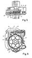
- Fig 4 is a front view of the arrangement when the brake is activated by the coasting brake
- Fig. 5 and 6 is the corresponding plan view and rear view
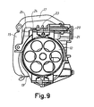
- Fig. 7 is a front view of the arrangement when it has been activated by the kick brake
- Fig. 8 and 9 is the corresponding plan view and rear view.
- a chain saw is in a conventional way provided with an electric motor 10 that rotates an outlet shaft 11 that via a transmission and a sprocket wheel (not shown) drives the saw chain around the saw bar.
- the outlet shaft 11 is also provided with a brake drum 12 that is surrounded by a brake band 13 having one end fixed to a base structure 14 of the chain saw whereas the other end of the brake band is secured to a first end of an elongated brake lever 15.
- the brake lever is at its mid part turnably arranged about a shaft 16 that is fixed to the base structure 14 whereas the second end of the lever 15 is turnably secured to a link arm mechanism that comprises a first and a second arm 17 and 18 resp.
- the first arm 17 is at one end coupled to said lever 15 whereas it at its other end via a dowel 19 is pivotally connected to one end of the second arm 18 which is shorter than the first arm.
- the dowel 19 is preferably under the influence of a spring (not shown) that creates a force F that pushes the dowel downwards in Fig. 1 .
- the other end of the second arm is pivotally connected to a slider 20 that is movable sideways in Fig. 1 in a guide 21 arranged at the base structure.
- the link arm mechanism constitutes a knee shaped structure that can be turned such that the connection between the first and second link arm in one "locked" position rests against an abutment surface 22 on the slider 20 whereas the connection part can be released from this position by a triggering arrangement that is connected to a conventional turnable hand protector (not shown) arranged at the chain saw and that applies an upwardly directed force in Fig. 1 on the dowel 19 when the hand protector is activated.
- the arrangement also comprises a tension spring 23 of the helical type. One end of this spring is secured to the slider 20 whereas the other end is in engagement with the brake lever 15 close to the turning connection between the lever 15 and the first arm 17.
- the tension spring 23 encloses a coaxial compression spring 24 of the helical type. One end of the compression spring 24 rests against a seat 25 that is a part of the base structure 14 whereas the other end rest against the slider 20.
- the slider 20 is linearly movable in the guide 21 by means of an element 26 that by means of a mechanical transmission (not shown) is connected to a throttle knob arranged in the operating handle of the chain saw.
- the arrangement operates in the following manner.
- the brake is not activated as appears from Fig. 1-3 since the throttle knob is depressed thereby keeping the slider 20 is in its right hand position in Fig. 1 . Consequently the forces from the throttle knob will be transferred to the slider 20 and further to the second and first arms 18 and 17, which are in the locked position where they engage the abutment surface 22, as well as to the brake lever 15.
- the upper part of the lever is in a right hand position in Fig. 1 whereas the lower part is in a left hand position causing the brake band 13 to be out of engagement with the brake drum.
- the compression spring 24 is in its compressed state.
- the kick brake becomes activated in order to immediately stop the chain from running, the situation is such as shown in Figs. 7-9 .
- the hand protector has been turned and by means of a transmission element acted on the dowel 19 and moved the connecting ends of the link arms 18, 17 upwards to the position shown in Fig. 7 .
Landscapes
- Life Sciences & Earth Sciences (AREA)
- Engineering & Computer Science (AREA)
- Mechanical Engineering (AREA)
- Wood Science & Technology (AREA)
- Forests & Forestry (AREA)
- Braking Arrangements (AREA)
- Sawing (AREA)
Claims (9)
- Scie à chaîne à moteur avec un agencement de frein de chaîne comprenant un frein à rebond et un frein à inertie qui, par l'intermédiaire d'un mécanisme à bras de liaison, agissent sur un levier de frein (15) qui est agencé en pivotement sur un arbre (16) fixé directement ou indirectement à une structure de base de scie à chaîne (14), ledit levier de frein étant relié à une bande de frein (13) agissant sur un tambour de frein (12) qui est relié en entraînement avec l'arbre de sortie (11) du moteur, caractérisée en ce que le mécanisme à bras de liaison est relié à un coulisseau (20) qui peut se déplacer par rapport à ladite structure de base (14).
- Scie à chaîne selon la revendication 1, caractérisée en ce que ledit mécanisme à bras de liaison comprend un premier bras (18) et un deuxième bras (17) qui sont agencés en rotation l'un par rapport à l'autre, le premier bras (18) étant agencé en rotation par rapport au levier de frein (15) tandis que le deuxième bras est agencé en rotation par rapport au coulisseau (20).
- Scie à chaîne selon la revendication 2, caractérisée en ce que le levier de frein (15) est allongé et la bande de frein (13) est reliée à une extrémité du levier de frein et le deuxième bras (17) est relié à l'autre extrémité du levier tandis que l'arbre (16) est agencé entre lesdites extrémités.
- Scie à chaîne selon l'une des revendications précédentes, caractérisée en ce qu'un ressort de traction (23) est agencé entre le coulisseau (20) et le levier de frein (15).
- Scie à chaîne selon l'une des revendications précédentes, caractérisée en ce qu'un ressort de compression (24) est agencé entre le coulisseau (20) et la Structure de base (14).
- Scie à chaîne selon les revendications 4 et 5, caractérisée en ce que le ressort de traction (23) ainsi que le ressort de compression (24) sont des ressorts hélicoïdaux qui sont agencés de manière coaxiale.
- Scie à chaîne selon l'une des revendications précédentes, caractérisée en ce que le mouvement dudit coulisseau (20) est sous l'influence d'un agencement de transmission relié à un levier de manette des gaz.
- Scie à chaîne selon l'une des revendications précédentes, caractérisée en ce que le mécanisme à bras de liaison, au moyen d'un élément de protection des mains, peut se déplacer d'une première position verrouillée dans laquelle une partie du mécanisme est dans une position de repos contre une surface de butée (22) vers une deuxième position de libération dans laquelle ladite partie est libérée de la surface de butée (22).
- Scie à chaîne selon la revendication 8, caractérisée en ce que le mécanisme à bras de liaison est sous l'influence d'un ressort qui pousse ladite partie contre la surface de butée (22).
Applications Claiming Priority (2)
| Application Number | Priority Date | Filing Date | Title |
|---|---|---|---|
| SE0402907A SE0402907D0 (sv) | 2004-11-29 | 2004-11-29 | Chain saw brake arrangement |
| PCT/SE2005/001510 WO2006057589A1 (fr) | 2004-11-29 | 2005-10-11 | Mecanisme de frein pour scie a chaine |
Publications (3)
| Publication Number | Publication Date |
|---|---|
| EP1817144A1 EP1817144A1 (fr) | 2007-08-15 |
| EP1817144A4 EP1817144A4 (fr) | 2013-09-25 |
| EP1817144B1 true EP1817144B1 (fr) | 2014-08-13 |
Family
ID=33538407
Family Applications (1)
| Application Number | Title | Priority Date | Filing Date |
|---|---|---|---|
| EP05792433.4A Expired - Lifetime EP1817144B1 (fr) | 2004-11-29 | 2005-10-11 | Mecanisme de frein pour scie a chaine |
Country Status (3)
| Country | Link |
|---|---|
| EP (1) | EP1817144B1 (fr) |
| SE (1) | SE0402907D0 (fr) |
| WO (1) | WO2006057589A1 (fr) |
Families Citing this family (2)
| Publication number | Priority date | Publication date | Assignee | Title |
|---|---|---|---|---|
| WO2015133940A1 (fr) * | 2014-03-04 | 2015-09-11 | Husqvarna Ab | Système de commande de frein de fonctionnement débrayé |
| US12064894B2 (en) | 2020-09-04 | 2024-08-20 | Milwaukee Electric Tool Corporation | Chainsaw |
Family Cites Families (10)
| Publication number | Priority date | Publication date | Assignee | Title |
|---|---|---|---|---|
| SU893519A1 (ru) * | 1980-02-08 | 1981-12-30 | Центральный Научно-Исследовательский И Проектно-Конструкторский Институт Механизации И Энергетики Лесной Промышленности | Тормозное устройство дл пильной цепи моторной пилы |
| SE457626B (sv) * | 1983-07-08 | 1989-01-16 | Stihl Maschf Andreas | Kedjebromanordning |
| DE3530685C5 (de) * | 1985-08-28 | 2005-07-21 | Fa. Andreas Stihl | Elektrische Motorkettensäge |
| DE3608523A1 (de) * | 1986-03-14 | 1987-09-17 | Bosch Gmbh Robert | Schnellstoppeinrichtung zum stillsetzen einer saegekette einer tragbaren motorkettensaege |
| DE3639650A1 (de) * | 1986-11-20 | 1988-06-01 | Stihl Maschf Andreas | Motorkettensaege |
| DE4330850A1 (de) * | 1993-09-11 | 1995-03-16 | Stihl Maschf Andreas | Mechanisches Zweikreis-Bremssystem |
| DE19618640C2 (de) * | 1995-05-11 | 2001-02-15 | Stihl Maschf Andreas | Motorkettensäge mit einer Kettenbremseinrichtung |
| GB9804796D0 (en) * | 1998-03-06 | 1998-04-29 | Black & Decker Inc | Clutch mechanism for a chain saw |
| DE19931251A1 (de) * | 1999-07-07 | 2001-01-11 | Bosch Gmbh Robert | Motorkettensäge |
| DE20009070U1 (de) * | 2000-05-19 | 2001-09-27 | Dolmar GmbH, 22045 Hamburg | Motorkettensäge mit Rückschlagbremse und Auslaufbremse |
-
2004
- 2004-11-29 SE SE0402907A patent/SE0402907D0/sv unknown
-
2005
- 2005-10-11 WO PCT/SE2005/001510 patent/WO2006057589A1/fr not_active Ceased
- 2005-10-11 EP EP05792433.4A patent/EP1817144B1/fr not_active Expired - Lifetime
Also Published As
| Publication number | Publication date |
|---|---|
| EP1817144A1 (fr) | 2007-08-15 |
| WO2006057589A1 (fr) | 2006-06-01 |
| EP1817144A4 (fr) | 2013-09-25 |
| SE0402907D0 (sv) | 2004-11-29 |
Similar Documents
| Publication | Publication Date | Title |
|---|---|---|
| JP2759072B2 (ja) | チェーン制動装置を備えた動力チェーンソー | |
| JP3338543B2 (ja) | ヘッジトリマ | |
| JP2889433B2 (ja) | 制動装置をスプロケットカバーに統合したチェーンソー | |
| CA1170548A (fr) | Dispositif d'arret ameliore pour outil portatif | |
| JP3135557B2 (ja) | 作業機の動力駆動作業工具を停止させるためのブレーキ装置を操作する装置 | |
| CN1907613B (zh) | 链锯的改进或与链锯相关的改进 | |
| EP1066933A2 (fr) | Scie à chaíne à dispositif pour freiner la chaíne coupante | |
| EP1817144B1 (fr) | Mecanisme de frein pour scie a chaine | |
| CN1689776A (zh) | 马达链锯 | |
| US8176643B2 (en) | Brake system of chain saw and chain saw | |
| CN207140006U (zh) | 链锯的制动装置 | |
| EP1663589B1 (fr) | Scie à chaîne avec dispositif de commande par etranglement | |
| US20100218388A1 (en) | Chainsaw throttle and brake mechanisms | |
| JP5114377B2 (ja) | 動力工具 | |
| EP1650092B1 (fr) | Dispositif de réduction de bruit pour un frein de stationnement | |
| EP2969426B1 (fr) | Scie à chaîne avec un mécanisme de frein d'entraînement débrayé/de frein de chaîne | |
| JP2004053015A (ja) | アクチュエータユニット | |
| JP4278102B2 (ja) | 作業機の制動装置 | |
| US6742265B2 (en) | Hand guard block | |
| JP3373477B2 (ja) | ヘッジトリマ | |
| WO1994013441A2 (fr) | Mecanisme de securite pour outil a moteur | |
| EP0677361A1 (fr) | Scie à chaîne avec frein compact | |
| JPH08336809A (ja) | チェーンソーのブレーキ装置 | |
| FR2857290A3 (fr) | Dispositif de securite pour tronconneuse electrique ou tronconneuse mecanique | |
| CA1205360A (fr) | Commande de mise en marche pour moteur de scie a chaine |
Legal Events
| Date | Code | Title | Description |
|---|---|---|---|
| PUAI | Public reference made under article 153(3) epc to a published international application that has entered the european phase |
Free format text: ORIGINAL CODE: 0009012 |
|
| 17P | Request for examination filed |
Effective date: 20070426 |
|
| AK | Designated contracting states |
Kind code of ref document: A1 Designated state(s): AT BE BG CH CY CZ DE DK EE ES FI FR GB GR HU IE IS IT LI LT LU LV MC NL PL PT RO SE SI SK TR |
|
| DAX | Request for extension of the european patent (deleted) | ||
| RIC1 | Information provided on ipc code assigned before grant |
Ipc: B27G 19/00 20060101ALI20130814BHEP Ipc: B27B 17/08 20060101AFI20130814BHEP |
|
| A4 | Supplementary search report drawn up and despatched |
Effective date: 20130822 |
|
| GRAP | Despatch of communication of intention to grant a patent |
Free format text: ORIGINAL CODE: EPIDOSNIGR1 |
|
| INTG | Intention to grant announced |
Effective date: 20140520 |
|
| GRAS | Grant fee paid |
Free format text: ORIGINAL CODE: EPIDOSNIGR3 |
|
| GRAA | (expected) grant |
Free format text: ORIGINAL CODE: 0009210 |
|
| AK | Designated contracting states |
Kind code of ref document: B1 Designated state(s): AT BE BG CH CY CZ DE DK EE ES FI FR GB GR HU IE IS IT LI LT LU LV MC NL PL PT RO SE SI SK TR |
|
| REG | Reference to a national code |
Ref country code: GB Ref legal event code: FG4D |
|
| REG | Reference to a national code |
Ref country code: AT Ref legal event code: REF Ref document number: 681922 Country of ref document: AT Kind code of ref document: T Effective date: 20140815 Ref country code: CH Ref legal event code: EP |
|
| REG | Reference to a national code |
Ref country code: IE Ref legal event code: FG4D |
|
| REG | Reference to a national code |
Ref country code: DE Ref legal event code: R096 Ref document number: 602005044487 Country of ref document: DE Effective date: 20140925 |
|
| REG | Reference to a national code |
Ref country code: NL Ref legal event code: VDEP Effective date: 20140813 |
|
| REG | Reference to a national code |
Ref country code: AT Ref legal event code: MK05 Ref document number: 681922 Country of ref document: AT Kind code of ref document: T Effective date: 20140813 |
|
| REG | Reference to a national code |
Ref country code: LT Ref legal event code: MG4D |
|
| PG25 | Lapsed in a contracting state [announced via postgrant information from national office to epo] |
Ref country code: LT Free format text: LAPSE BECAUSE OF FAILURE TO SUBMIT A TRANSLATION OF THE DESCRIPTION OR TO PAY THE FEE WITHIN THE PRESCRIBED TIME-LIMIT Effective date: 20140813 Ref country code: GR Free format text: LAPSE BECAUSE OF FAILURE TO SUBMIT A TRANSLATION OF THE DESCRIPTION OR TO PAY THE FEE WITHIN THE PRESCRIBED TIME-LIMIT Effective date: 20141114 Ref country code: FI Free format text: LAPSE BECAUSE OF FAILURE TO SUBMIT A TRANSLATION OF THE DESCRIPTION OR TO PAY THE FEE WITHIN THE PRESCRIBED TIME-LIMIT Effective date: 20140813 Ref country code: BG Free format text: LAPSE BECAUSE OF FAILURE TO SUBMIT A TRANSLATION OF THE DESCRIPTION OR TO PAY THE FEE WITHIN THE PRESCRIBED TIME-LIMIT Effective date: 20141113 Ref country code: PT Free format text: LAPSE BECAUSE OF FAILURE TO SUBMIT A TRANSLATION OF THE DESCRIPTION OR TO PAY THE FEE WITHIN THE PRESCRIBED TIME-LIMIT Effective date: 20141215 Ref country code: ES Free format text: LAPSE BECAUSE OF FAILURE TO SUBMIT A TRANSLATION OF THE DESCRIPTION OR TO PAY THE FEE WITHIN THE PRESCRIBED TIME-LIMIT Effective date: 20140813 Ref country code: SE Free format text: LAPSE BECAUSE OF FAILURE TO SUBMIT A TRANSLATION OF THE DESCRIPTION OR TO PAY THE FEE WITHIN THE PRESCRIBED TIME-LIMIT Effective date: 20140813 |
|
| PG25 | Lapsed in a contracting state [announced via postgrant information from national office to epo] |
Ref country code: AT Free format text: LAPSE BECAUSE OF FAILURE TO SUBMIT A TRANSLATION OF THE DESCRIPTION OR TO PAY THE FEE WITHIN THE PRESCRIBED TIME-LIMIT Effective date: 20140813 Ref country code: LV Free format text: LAPSE BECAUSE OF FAILURE TO SUBMIT A TRANSLATION OF THE DESCRIPTION OR TO PAY THE FEE WITHIN THE PRESCRIBED TIME-LIMIT Effective date: 20140813 Ref country code: IS Free format text: LAPSE BECAUSE OF FAILURE TO SUBMIT A TRANSLATION OF THE DESCRIPTION OR TO PAY THE FEE WITHIN THE PRESCRIBED TIME-LIMIT Effective date: 20141213 Ref country code: CY Free format text: LAPSE BECAUSE OF FAILURE TO SUBMIT A TRANSLATION OF THE DESCRIPTION OR TO PAY THE FEE WITHIN THE PRESCRIBED TIME-LIMIT Effective date: 20140813 |
|
| PG25 | Lapsed in a contracting state [announced via postgrant information from national office to epo] |
Ref country code: NL Free format text: LAPSE BECAUSE OF FAILURE TO SUBMIT A TRANSLATION OF THE DESCRIPTION OR TO PAY THE FEE WITHIN THE PRESCRIBED TIME-LIMIT Effective date: 20140813 |
|
| PG25 | Lapsed in a contracting state [announced via postgrant information from national office to epo] |
Ref country code: RO Free format text: LAPSE BECAUSE OF FAILURE TO SUBMIT A TRANSLATION OF THE DESCRIPTION OR TO PAY THE FEE WITHIN THE PRESCRIBED TIME-LIMIT Effective date: 20140813 Ref country code: CZ Free format text: LAPSE BECAUSE OF FAILURE TO SUBMIT A TRANSLATION OF THE DESCRIPTION OR TO PAY THE FEE WITHIN THE PRESCRIBED TIME-LIMIT Effective date: 20140813 Ref country code: EE Free format text: LAPSE BECAUSE OF FAILURE TO SUBMIT A TRANSLATION OF THE DESCRIPTION OR TO PAY THE FEE WITHIN THE PRESCRIBED TIME-LIMIT Effective date: 20140813 Ref country code: IT Free format text: LAPSE BECAUSE OF FAILURE TO SUBMIT A TRANSLATION OF THE DESCRIPTION OR TO PAY THE FEE WITHIN THE PRESCRIBED TIME-LIMIT Effective date: 20140813 Ref country code: DK Free format text: LAPSE BECAUSE OF FAILURE TO SUBMIT A TRANSLATION OF THE DESCRIPTION OR TO PAY THE FEE WITHIN THE PRESCRIBED TIME-LIMIT Effective date: 20140813 Ref country code: SK Free format text: LAPSE BECAUSE OF FAILURE TO SUBMIT A TRANSLATION OF THE DESCRIPTION OR TO PAY THE FEE WITHIN THE PRESCRIBED TIME-LIMIT Effective date: 20140813 |
|
| REG | Reference to a national code |
Ref country code: DE Ref legal event code: R097 Ref document number: 602005044487 Country of ref document: DE |
|
| PG25 | Lapsed in a contracting state [announced via postgrant information from national office to epo] |
Ref country code: LU Free format text: LAPSE BECAUSE OF FAILURE TO SUBMIT A TRANSLATION OF THE DESCRIPTION OR TO PAY THE FEE WITHIN THE PRESCRIBED TIME-LIMIT Effective date: 20141011 Ref country code: PL Free format text: LAPSE BECAUSE OF FAILURE TO SUBMIT A TRANSLATION OF THE DESCRIPTION OR TO PAY THE FEE WITHIN THE PRESCRIBED TIME-LIMIT Effective date: 20140813 Ref country code: MC Free format text: LAPSE BECAUSE OF FAILURE TO SUBMIT A TRANSLATION OF THE DESCRIPTION OR TO PAY THE FEE WITHIN THE PRESCRIBED TIME-LIMIT Effective date: 20140813 |
|
| REG | Reference to a national code |
Ref country code: CH Ref legal event code: PL |
|
| PLBE | No opposition filed within time limit |
Free format text: ORIGINAL CODE: 0009261 |
|
| STAA | Information on the status of an ep patent application or granted ep patent |
Free format text: STATUS: NO OPPOSITION FILED WITHIN TIME LIMIT |
|
| PG25 | Lapsed in a contracting state [announced via postgrant information from national office to epo] |
Ref country code: BE Free format text: LAPSE BECAUSE OF NON-PAYMENT OF DUE FEES Effective date: 20141031 |
|
| 26N | No opposition filed |
Effective date: 20150515 |
|
| REG | Reference to a national code |
Ref country code: IE Ref legal event code: MM4A |
|
| PG25 | Lapsed in a contracting state [announced via postgrant information from national office to epo] |
Ref country code: CH Free format text: LAPSE BECAUSE OF NON-PAYMENT OF DUE FEES Effective date: 20141031 Ref country code: LI Free format text: LAPSE BECAUSE OF NON-PAYMENT OF DUE FEES Effective date: 20141031 |
|
| REG | Reference to a national code |
Ref country code: FR Ref legal event code: PLFP Year of fee payment: 11 |
|
| PG25 | Lapsed in a contracting state [announced via postgrant information from national office to epo] |
Ref country code: IE Free format text: LAPSE BECAUSE OF NON-PAYMENT OF DUE FEES Effective date: 20141011 |
|
| PGFP | Annual fee paid to national office [announced via postgrant information from national office to epo] |
Ref country code: GB Payment date: 20150904 Year of fee payment: 11 |
|
| PG25 | Lapsed in a contracting state [announced via postgrant information from national office to epo] |
Ref country code: SI Free format text: LAPSE BECAUSE OF FAILURE TO SUBMIT A TRANSLATION OF THE DESCRIPTION OR TO PAY THE FEE WITHIN THE PRESCRIBED TIME-LIMIT Effective date: 20140813 |
|
| PGFP | Annual fee paid to national office [announced via postgrant information from national office to epo] |
Ref country code: FR Payment date: 20150918 Year of fee payment: 11 |
|
| PGFP | Annual fee paid to national office [announced via postgrant information from national office to epo] |
Ref country code: DE Payment date: 20150825 Year of fee payment: 11 |
|
| PG25 | Lapsed in a contracting state [announced via postgrant information from national office to epo] |
Ref country code: TR Free format text: LAPSE BECAUSE OF FAILURE TO SUBMIT A TRANSLATION OF THE DESCRIPTION OR TO PAY THE FEE WITHIN THE PRESCRIBED TIME-LIMIT Effective date: 20140813 Ref country code: HU Free format text: LAPSE BECAUSE OF FAILURE TO SUBMIT A TRANSLATION OF THE DESCRIPTION OR TO PAY THE FEE WITHIN THE PRESCRIBED TIME-LIMIT; INVALID AB INITIO Effective date: 20051011 Ref country code: BE Free format text: LAPSE BECAUSE OF FAILURE TO SUBMIT A TRANSLATION OF THE DESCRIPTION OR TO PAY THE FEE WITHIN THE PRESCRIBED TIME-LIMIT Effective date: 20140813 |
|
| REG | Reference to a national code |
Ref country code: DE Ref legal event code: R119 Ref document number: 602005044487 Country of ref document: DE |
|
| GBPC | Gb: european patent ceased through non-payment of renewal fee |
Effective date: 20161011 |
|
| REG | Reference to a national code |
Ref country code: FR Ref legal event code: ST Effective date: 20170630 |
|
| PG25 | Lapsed in a contracting state [announced via postgrant information from national office to epo] |
Ref country code: GB Free format text: LAPSE BECAUSE OF NON-PAYMENT OF DUE FEES Effective date: 20161011 Ref country code: FR Free format text: LAPSE BECAUSE OF NON-PAYMENT OF DUE FEES Effective date: 20161102 Ref country code: DE Free format text: LAPSE BECAUSE OF NON-PAYMENT OF DUE FEES Effective date: 20170503 |