EP1817155B1 - Flexibler dorn für einen hochkonturierten verbundstringer und verfahren zur hertsellung eines hochkonturierten verbundstringers - Google Patents
Flexibler dorn für einen hochkonturierten verbundstringer und verfahren zur hertsellung eines hochkonturierten verbundstringers Download PDFInfo
- Publication number
- EP1817155B1 EP1817155B1 EP05858299A EP05858299A EP1817155B1 EP 1817155 B1 EP1817155 B1 EP 1817155B1 EP 05858299 A EP05858299 A EP 05858299A EP 05858299 A EP05858299 A EP 05858299A EP 1817155 B1 EP1817155 B1 EP 1817155B1
- Authority
- EP
- European Patent Office
- Prior art keywords
- mandrel
- assembly
- contoured
- mandrel element
- slots
- Prior art date
- Legal status (The legal status is an assumption and is not a legal conclusion. Google has not performed a legal analysis and makes no representation as to the accuracy of the status listed.)
- Expired - Lifetime
Links
Images

Classifications
-
- B—PERFORMING OPERATIONS; TRANSPORTING
- B29—WORKING OF PLASTICS; WORKING OF SUBSTANCES IN A PLASTIC STATE IN GENERAL
- B29C—SHAPING OR JOINING OF PLASTICS; SHAPING OF MATERIAL IN A PLASTIC STATE, NOT OTHERWISE PROVIDED FOR; AFTER-TREATMENT OF THE SHAPED PRODUCTS, e.g. REPAIRING
- B29C70/00—Shaping composites, i.e. plastics material comprising reinforcements, fillers or preformed parts, e.g. inserts
- B29C70/04—Shaping composites, i.e. plastics material comprising reinforcements, fillers or preformed parts, e.g. inserts comprising reinforcements only, e.g. self-reinforcing plastics
- B29C70/28—Shaping operations therefor
- B29C70/30—Shaping by lay-up, i.e. applying fibres, tape or broadsheet on a mould, former or core; Shaping by spray-up, i.e. spraying of fibres on a mould, former or core
- B29C70/34—Shaping by lay-up, i.e. applying fibres, tape or broadsheet on a mould, former or core; Shaping by spray-up, i.e. spraying of fibres on a mould, former or core and shaping or impregnating by compression, i.e. combined with compressing after the lay-up operation
- B29C70/345—Shaping by lay-up, i.e. applying fibres, tape or broadsheet on a mould, former or core; Shaping by spray-up, i.e. spraying of fibres on a mould, former or core and shaping or impregnating by compression, i.e. combined with compressing after the lay-up operation using matched moulds
-
- B—PERFORMING OPERATIONS; TRANSPORTING
- B29—WORKING OF PLASTICS; WORKING OF SUBSTANCES IN A PLASTIC STATE IN GENERAL
- B29C—SHAPING OR JOINING OF PLASTICS; SHAPING OF MATERIAL IN A PLASTIC STATE, NOT OTHERWISE PROVIDED FOR; AFTER-TREATMENT OF THE SHAPED PRODUCTS, e.g. REPAIRING
- B29C70/00—Shaping composites, i.e. plastics material comprising reinforcements, fillers or preformed parts, e.g. inserts
- B29C70/04—Shaping composites, i.e. plastics material comprising reinforcements, fillers or preformed parts, e.g. inserts comprising reinforcements only, e.g. self-reinforcing plastics
- B29C70/28—Shaping operations therefor
- B29C70/40—Shaping or impregnating by compression not applied
- B29C70/42—Shaping or impregnating by compression not applied for producing articles of definite length, i.e. discrete articles
- B29C70/44—Shaping or impregnating by compression not applied for producing articles of definite length, i.e. discrete articles using isostatic pressure, e.g. pressure difference-moulding, vacuum bag-moulding, autoclave-moulding or expanding rubber-moulding
- B29C70/446—Moulding structures having an axis of symmetry or at least one channel, e.g. tubular structures, frames
-
- B—PERFORMING OPERATIONS; TRANSPORTING
- B29—WORKING OF PLASTICS; WORKING OF SUBSTANCES IN A PLASTIC STATE IN GENERAL
- B29L—INDEXING SCHEME ASSOCIATED WITH SUBCLASS B29C, RELATING TO PARTICULAR ARTICLES
- B29L2031/00—Other particular articles
- B29L2031/30—Vehicles, e.g. ships or aircraft, or body parts thereof
- B29L2031/3076—Aircrafts
- B29L2031/3085—Wings
-
- Y—GENERAL TAGGING OF NEW TECHNOLOGICAL DEVELOPMENTS; GENERAL TAGGING OF CROSS-SECTIONAL TECHNOLOGIES SPANNING OVER SEVERAL SECTIONS OF THE IPC; TECHNICAL SUBJECTS COVERED BY FORMER USPC CROSS-REFERENCE ART COLLECTIONS [XRACs] AND DIGESTS
- Y02—TECHNOLOGIES OR APPLICATIONS FOR MITIGATION OR ADAPTATION AGAINST CLIMATE CHANGE
- Y02T—CLIMATE CHANGE MITIGATION TECHNOLOGIES RELATED TO TRANSPORTATION
- Y02T50/00—Aeronautics or air transport
- Y02T50/40—Weight reduction
Definitions
- the present invention relates generally to an aircraft composite stringer mandrel and more particularly to a flexible mandrel for the use with an aircraft stringer lay-up assembly to produce a contoured composite stringer element.
- Aircraft components such as stringers have become complex in design and shape due to developing aircraft designs.
- the complexity of shape in combination with a need for decreased weight/strength ratios requires the use of alternate construction technologies. For this reason, aircraft designers have turned to the use of composite ply assemblies for the manufacture of aircraft stringers.
- a material ply impregnated with epoxy or similar substance is layed-up onto a mandrel shaped to generated the complex shape.
- the composite ply assembly is then cured to generate a composite component with the desired complex shape.
- United States patent no. 2739350 states that "the present invention is directed to a method and means of forming hollow ducts of plasticized glass fiber cloth for use in airplanes to transmit air from a source such as a ram air intake for example, to other regions of the airplane to be used for air conditioning and cooling purposes".
- an aircraft stringer lay-up assembly comprising a contoured curing block and a first mandrel element positioned thereon.
- the first mandrel assembly includes a first bar assembly having a plurality of rigidity reducing first slots formed along a first mandrel length. The plurality of rigidity reducing first slots protruding partially through a first mandrel depth of the first mandrel element to allow the first bar assembly to conform to the contoured curing block.
- a composite ply assembly can be laid up onto the first mandrel element and cured while conformed to said contoured curing block so as to generate a contoured composite stringer element.
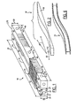
- FIGURE 1 is an illustration of an aircraft stringer lay-up assembly in accordance with the present invention, the assembly illustrated showing a first and second mandrel assembly;
- FIGURE 2 is an illustration of a contoured curing block for use in the aircraft stringer lay-up assembly illustrated in Figure 1 ;
- FIGURE 3 is an illustration of an aircraft stringer lay-up assembly in accordance with the present invention, the illustration showing the arrangement of components from Figures 1 and 2 in addition to the composite ply assembly;
- FIGURE 4 is an illustration of the aircraft stringer lay-up assembly illustrated in Figure 3 , the illustration showing the addition of a vacuum bag assembly and clamping elements;
- FIGURE 5 is an illustration of the aircraft stringer lay-up assembly illustrated in Figure 4 , the assembly subjected to a curing process;
- FIGURE 6 is an illustration of a contoured composite stringer element generated from the aircraft stringer lay-up assembly illustrated in the above figures.
- the aircraft stringer lay-up assembly 10 includes a first mandrel element 12 and a second mandrel element 14.
- the mandrel elements 12, 14 are preferably elongated metal beams as illustrated.
- Traditional metal mandrel configurations suffer from an inability to conform to the complex arrangements necessary for modem stringer lay-up requirements.
- the present invention provides a unique approach by constructing the first mandrel element 12 from a first bar assembly 16 having a plurality of rigidity reducing first elements 18 formed along its first mandrel length 20. Although a variety of rigidity reducing element 18 are contemplated, one embodiment contemplates the use of slots.
- the first mandrel element 12 includes two mandrel vertical surfaces 22, two mandrel side surfaces 24, a right mandrel end surface 26 and a left mandrel end surface 28.
- the vertical surfaces 22 may be further defined as a first mandrel upper vertical surface 30 and a first mandrel lower vertical surface 32.
- the plurality of rigidity reducing first slots 18 protrude partially through a first mandrel depth 34 from one of the first mandrel vertical surfaces 22 through both of the mandrel side surfaces 24. This allows the first bar assembly 16 to flex and twist when a plurality of such rigidity reducing first slots 18 are introduced.
- one embodiment contemplates the use of a plurality of tapered slots 36, each of which has an open end 38 and a tapered end 40.
- the open end is formed on the first mandrel vertical surface 22 and the tapered end 40 is formed partially through the first mandrel depth 34 such that it is visible from both the first mandrel side surfaces 24.
- straight slots are also contemplated.
- the slots may be formed by wire electrical discharged machining such that they may be maintained as very thin slots so as not to disturb the lay-up surfaces of the first mandrel element 12. It is contemplated that the slots 18 will be kept less than 0.01 inches wide and in one embodiment they are 0.0065 inches wide. This allows the desired flexibility of the first mandrel element 12 without impacting lay-up surfaces.
- the plurality of rigidity reducing first slots (elements) 18 may be formed in a variety of arrangements along the first mandrel length 20.
- the rigidity reducing first slots 18 may be formed as a first group of rigidity reducing first slots 42 and a second grouping of rigidity reducing slots 44.
- the first grouping 42 is formed on the first mandrel upper vertical surface 30 while the second grouping 44 is formed on the first mandrel lower vertical surface 32.
- Each of the plurality of rigidity reducing slots 18 is preferably grouped such that the bending of the first mandrel element 12 tends to close the slots rather than open them. This again preserves the surfaces for lay-up.
- the groupings 42, 44 are positioned at opposing ends, however, a wide variety of groupings and spacings are contemplated.
- the second mandrel element 14 may be similarly comprised of a plurality of rigidity reducing second slots 46 along a second mandrel length 48. These second slots 46 protrude partially through a second mandrel depth 50 and may be positioned on either or both of the second mandrel upper vertical surface 52 or the second mandrel lower vertical surface 54.
- the contoured curing block 56 includes a complex contour 58 that can be complex in both a first curing block planar direction 60 and a second curing block planar direction 62. This allows twist to be induced.
- the weight of the mandrel can be utilized to conform it into the complex contour 58.
- a vacuum bag assembly 64 see Figure 5
- a clamping assembly 66 see Figure 4
- a composite ply assembly 68 may be layed-up on the mandrel elements 12,14.
- the composite ply assembly 68 may be laid up between the mandrels 12,14 and even between the mandrels 12, 14 and the curing block 56. By laying up the composite ply assembly 68 between the mandrels 12,14 and over the upper vertical surfaces 30,52 and lower vertical surfaces 32,54, an I-beam arrangement is generated.
- the composite ply assembly 68 is subjected to curing, commonly through the application of a curing heat 70 (see Figure 5 ), wherein it is hardened into a contoured composite stringer element 72 such as the contoured I-beam element illustrated in Figure 6 .
- the present invention further contemplates the use of a plurality of side positioning bores 74 positioned along the mandrel side surfaces 24. This allows the mandrel elements 12,14 to be easily moved and positioned on the contoured curing block 56. In addition, they may be utilized as additional clamping or weighting points to assure proper conformation with the curing block 56 in particularly complex surface areas. Additionally, the present invention contemplates the use of a central bore 76 formed through the first mandrel length 20. A center support wire 78 is positioned within the central bore 76 and runs the length of the fist mandrel element 12. By inducing tension in the center support wire 78 the flexibility of the first mandrel element 12 may by varied thereby allowing the first mandrel element 12 to be utilized in a greater range of applications.
Landscapes
- Chemical & Material Sciences (AREA)
- Engineering & Computer Science (AREA)
- Composite Materials (AREA)
- Mechanical Engineering (AREA)
- Moulding By Coating Moulds (AREA)
- Casting Or Compression Moulding Of Plastics Or The Like (AREA)
- Shaping Of Tube Ends By Bending Or Straightening (AREA)
- Extrusion Moulding Of Plastics Or The Like (AREA)
Claims (11)
- Flugzeugstringer-Auflegeanordnung (10), aufweisend:einen konturierten Härtungsblock (56);ein erstes Dornelement (12), das auf dem konturierten Härtungsblock (56) positioniert ist, dadurch gekennzeichnet, dass das erste Dornelement (12) eine erste Stangenanordnung (16) mit mehreren entlang der Außenseite eines ersten Dornabschnittes (20) ausgebildeten steifigkeitsverringernden ersten Schlitzen (18) aufweist, wobei die mehreren steifigkeitsverringernden ersten Schlitze (18) teilweise durch eine erste Dorntiefe (34) des ersten Dornelementes (12) ragen, um der ersten Stangenanordnung (16) zu ermöglichen, sich dergestalt an den konturierten Härtungsblock (56) anzupassen, dass eine Verbundstofflagenanordnung (68) auf das erste Dornelement (12) aufgelegt und auf dem ersten Dornelement (12) unter Anpassung an den konturierten Härtungsblock (56) gehärtet werden kann, um so ein konturiertes Verbundstoff-Stringerelement (72) zu erzeugen.
- Flugzeugstringer-Auflegeanordnung (10) nach Anspruch 1, wobei die mehreren steifigkeitsverringernden ersten Schlitze (18) aufweisen:mehrere spitz zulaufende Schlitze (36) mit einem offenen Ende (38) und einem spitz zulaufenden Ende (40), wobei das offene Ende (38) entlang einer vertikalen Oberfläche (22) des ersten Dorns angeordnet ist, während das spitz zulaufende Ende (40) entlang einer Seitenoberfläche (24) des ersten Dorns angeordnet ist.
- Flugzeugstringer-Auflegeanordnung (10) nach Anspruch 1, ferner aufweisend:eine Vakuumsackanordnung (64), die den konturierten Härtungsblock (56), das erste Dornelement (12) und die Verbundstofflagenanordnung (68) umgibt, wobei die Vakuumsackanordnung (64) die Verbundstofflagenanordnung (68) gegen das erste Dornelement (12) während der Härtung anpresst.
- Flugzeugstringer-Auflegeanordnung (10) nach Anspruch 1, ferner aufweisend:eine Klemmanordnung (66), die das erste Dornelement (12) auf den konturierten Härtungsblock (56) drückt.
- Flugzeugstringer-Auflegeanordnung (10) nach Anspruch 1, ferner aufweisend:ein zweites Dornelement (14), das angrenzend an das erste Dornelement (12) auf dem konturierten Härtungsblock (56) positioniert ist, wobei das zweite Dornelement (14) mehrere steifigkeitsverringernde Schlitze (46) aufweist, die entlang einem zweiten Dornabschnitt (48) ausgebildet sind, wobei die mehreren steifigkeitsverringernden zweiten Schlitze (46) teilweise durch eine zweite Dorntiefe (50) des zweiten Dornelementes (14) ragen, um dem zweiten Dornelement (14) zu ermöglichen, sich dem konturierten Härtungsblock (56) anzupassen.
- Flugzeugstringer-Auflegeanordnung (10) nach Anspruch 5, wobei die Verbundstofflagenanordnung (68) zwischen dem ersten Dornelement (12) und dem zweiten Dornelement (14) aufgelegt wird, wobei sich die Verbundstofflagenanordnung (68) über eine obere vertikale Oberfläche (30) des ersten Dorns und eine obere vertikale Oberfläche (52) des zweiten Dorns erstreckt, wobei sich die Verbundstofflagenanordnung (68) über eine untere vertikale Oberfläche (32) eines ersten Dorns und eine untere vertikale Oberfläche (54) des zweiten Dorns dergestalt erstreckt, dass das konturierte Verbundstoff-Stringerelement (72) ein konturiertes I-Trägerelement umfasst.
- Verfahren zum Auflege-Herstellen eines Flugzeugstringers (10), mit den Schritten:Ausbilden mehrerer steifigkeitsverringernder erster Elemente (18) in einem Außenbereich eines ersten Dornelementes (12) entlang einem ersten Dornabschnitt (20);Platzieren des ersten Dornelementes (12) auf einem konturierten Härtungsblock (56), wobei die mehreren steifigkeitsverringernden ersten Elemente (18) eine Anpassung des ersten Dornelementes (12) an den konturierten Härtungsblock (56) ermöglichen;Auflegen einer Verbundstofflagenanordnung (68) auf das erste Dornelement (12), sobald das erste Dornelement (16) an dem konturierten Härtungsblock (56) angepasst ist; undAushärten der Verbundstofflagenanordnung (68) dergestalt, dass ein konturierter Verbundstoffstringer (72) erzeugt wird.
- Verfahren nach Anspruch 7, wobei die mehreren steifigkeitsverringernden ersten Elemente (18) als mehrere spitz zulaufende Schlitze (36) ausgebildet werden, die ein offenes Ende (38) und ein spitz zulaufendes Ende (40) enthalten, wobei das offene Ende (38) entlang einer vertikalen Oberfläche (22) des ersten Dorns positioniert ist, während das spitz zulaufende Ende (40) entlang einer Seitenoberfläche (24) des ersten Dorns positioniert ist.
- Verfahren nach Anspruch 7, ferner mit den Schritten:Einschließen des konturierten Härtungsblockes (56), des ersten Dornelementes (12) und der Verbundstofflagenanordnung (68) in einer Vakuumsackanordnung (64) vor der Härtung.
- Verfahren nach Anspruch 7, ferner mit den Schritten:Festklemmen des ersten Dornelementes (12) auf dem konturierten Härtungsblock (56) vor der Härtung.
- Verfahren nach Anspruch 7, ferner mit den Schritten:Ausbilden mehrerer steifigkeitsverringernder zweiter Schlitze (46) in einem zweiten Dornelement (14) entlang einem zweiten Dornabschnitt (48);Platzieren des zweiten Dornelementes (14) auf dem konturierten Härtungsblock (56) angrenzend an das erste Dornelement (12), wobei die mehreren steifigkeitsverringernden zweiten Schlitze (46) dem zweiten Dornelement (14) ermöglichen, sich an den konturierten Härtungsblock (56) anzupassen; undAuflegen der Verbundstofflagenanordnung (68) zwischen dem ersten Dornelement (12) und dem zweiten Dornelement (14), um einen konturierten Verbundstoffstringer (72) zu erzeugen.
Applications Claiming Priority (2)
| Application Number | Priority Date | Filing Date | Title |
|---|---|---|---|
| US10/904,717 US7357166B2 (en) | 2004-11-24 | 2004-11-24 | Flexible mandrel for highly contoured composite stringer |
| PCT/US2005/039967 WO2007001447A2 (en) | 2004-11-24 | 2005-11-04 | Flexible mandrel for highly contoured composite stringer and method of producing said stringer |
Publications (2)
| Publication Number | Publication Date |
|---|---|
| EP1817155A2 EP1817155A2 (de) | 2007-08-15 |
| EP1817155B1 true EP1817155B1 (de) | 2011-04-20 |
Family
ID=36459868
Family Applications (1)
| Application Number | Title | Priority Date | Filing Date |
|---|---|---|---|
| EP05858299A Expired - Lifetime EP1817155B1 (de) | 2004-11-24 | 2005-11-04 | Flexibler dorn für einen hochkonturierten verbundstringer und verfahren zur hertsellung eines hochkonturierten verbundstringers |
Country Status (7)
| Country | Link |
|---|---|
| US (2) | US7357166B2 (de) |
| EP (1) | EP1817155B1 (de) |
| JP (1) | JP4896035B2 (de) |
| AT (1) | ATE506173T1 (de) |
| DE (1) | DE602005027602D1 (de) |
| ES (1) | ES2364760T3 (de) |
| WO (1) | WO2007001447A2 (de) |
Families Citing this family (52)
| Publication number | Priority date | Publication date | Assignee | Title |
|---|---|---|---|---|
| EP1932652A1 (de) * | 2006-12-11 | 2008-06-18 | Saab Ab | Verfahren und Vorrichtung zur Herstellung eines gekrümmten, länglichen Strukturelements |
| US9238335B2 (en) * | 2008-07-10 | 2016-01-19 | The Boeing Company | Mandrel for autoclave curing applications |
| US9327467B2 (en) | 2008-07-10 | 2016-05-03 | The Boeing Company | Composite mandrel for autoclave curing applications |
| US8307872B2 (en) * | 2008-11-13 | 2012-11-13 | The Boeing Company | Apparatus for curing a composite structural member |
| US8293051B2 (en) | 2008-12-10 | 2012-10-23 | The Boeing Company | Method for producing composite laminates using a collapsible mandrel |
| US9296187B2 (en) | 2008-12-10 | 2016-03-29 | The Boeing Company | Bagging process and mandrel for fabrication of elongated composite structure |
| US8074694B2 (en) * | 2009-05-28 | 2011-12-13 | The Boeing Company | Stringer transition method |
| DE102010062871A1 (de) * | 2009-12-29 | 2011-06-30 | Airbus Operations GmbH, 21129 | Infusionsverfahren und Aufbau eines Infusionsverfahrens |
| ITTO20100175A1 (it) | 2010-03-08 | 2011-09-09 | Alenia Aeronautica Spa | Procedimento per la fabbricazione di longheroni alari e travi di fusoliera a doppio t in materiale composito a sezione variabile |
| US8430984B2 (en) | 2010-05-11 | 2013-04-30 | The Boeing Company | Collapsible mandrel employing reinforced fluoroelastomeric bladder |
| US8511359B2 (en) | 2010-09-23 | 2013-08-20 | The Boeing Company | Layup mandrel having changeable shape and method of using the same |
| US8795567B2 (en) * | 2010-09-23 | 2014-08-05 | The Boeing Company | Method for fabricating highly contoured composite stiffeners with reduced wrinkling |
| US8997642B2 (en) * | 2011-08-08 | 2015-04-07 | The Boeing Company | Method for transporting, placing and compacting composite stiffeners |
| US9931807B2 (en) | 2011-08-08 | 2018-04-03 | The Boeing Company | Flexible compactor with reinforcing spine |
| US8534339B2 (en) | 2011-10-12 | 2013-09-17 | The Boeing Company | Lightweight flexible mandrel and method for making the same |
| US9987772B1 (en) * | 2012-02-23 | 2018-06-05 | Mahmood Shareef | System and method to manufacture composite structures |
| JP5937894B2 (ja) * | 2012-06-04 | 2016-06-22 | 株式会社ジャムコ | 複合材ストリンガーの連続プリフォーム装置 |
| FR2991624B1 (fr) * | 2012-06-12 | 2015-03-06 | Airbus Operations Sas | Procede de realisation d'un profile courbe en materiau composite a partir d'une preforme rectiligne de nappes de fibres |
| US9333713B2 (en) | 2012-10-04 | 2016-05-10 | The Boeing Company | Method for co-curing composite skins and stiffeners in an autoclave |
| US9486943B1 (en) | 2012-10-31 | 2016-11-08 | The Boeing Company | Method for creating mandrels with voids for expansion control during curing |
| US9272767B2 (en) | 2013-04-19 | 2016-03-01 | The Boeing Company | Compacting uncured composite members on contoured mandrel surfaces |
| CN105682902B (zh) * | 2013-05-08 | 2018-02-06 | 艾普拉斯认证公司 | 用于形成复合材料的叠层的系统 |
| ITTO20131020A1 (it) * | 2013-12-13 | 2015-06-14 | Alenia Aermacchi Spa | Attrezzo e procedimento per la formatura e l'assemblaggio di longheroni di materiale composito |
| CN106132673B (zh) | 2014-03-04 | 2018-03-16 | 庞巴迪公司 | 使用透气聚乙烯真空膜形成复合叠层堆叠的方法和装置 |
| US9527572B2 (en) | 2014-06-26 | 2016-12-27 | The Boeing Company | Elongated structures and related assemblies |
| DE102014216160A1 (de) * | 2014-08-14 | 2016-02-18 | Airbus Operations Gmbh | Formkern, Verfahren und System zur Herstellung gekrümmter Verbundkomponenten |
| US9636876B2 (en) * | 2014-10-29 | 2017-05-02 | The Boeing Company | Method, device and apparatus for vacuum forming composite laminates |
| US9701070B2 (en) | 2014-11-06 | 2017-07-11 | Lockheed Martin Corporation | Mandrel forming for discrete wing skin stiffeners |
| US11072157B2 (en) | 2015-06-23 | 2021-07-27 | The Boeing Company | Method and apparatus for forming contoured stiffeners |
| US10059041B2 (en) | 2015-08-10 | 2018-08-28 | The Boeing Company | Multi-state bladder for manufacture of composite material |
| US9827720B2 (en) | 2015-08-10 | 2017-11-28 | The Boeing Company | Multi-state bladder for manufacture of composite material |
| US10399283B2 (en) | 2015-10-06 | 2019-09-03 | The Boeing Company | Method and device for producing contoured composite laminate stiffeners with reduced wrinkling |
| US10328611B2 (en) | 2015-10-09 | 2019-06-25 | The Boeing Company | Mechanical support tooling and/or mandrel for composite part curing |
| US10173349B2 (en) | 2016-01-21 | 2019-01-08 | The Boeing Company | Bladder that changes stiffness based on temperature effects for manufacture of composite components |
| US10272596B2 (en) | 2016-01-25 | 2019-04-30 | The Boeing Company | Electromagnetic support tooling for composite part curing |
| US10906210B2 (en) * | 2017-01-25 | 2021-02-02 | The Boeing Company | Mandrel for composite part fabrication and repair |
| JP6836474B2 (ja) | 2017-08-03 | 2021-03-03 | 三菱重工業株式会社 | 可撓性マンドレル、複合材部品の製造方法 |
| JP6971690B2 (ja) | 2017-08-03 | 2021-11-24 | 三菱重工業株式会社 | 可撓性マンドレル、複合材部品の製造方法 |
| US10882262B2 (en) * | 2018-08-22 | 2021-01-05 | The Boeing Company | Flexible mandrel for forming composite structures |
| ES2880625T3 (es) * | 2018-09-11 | 2021-11-25 | Airbus Operations Sl | Métodos para la fabricación de larguerillos curvos en omega y larguerillos en forma de Z de material compuesto y para la fabricación de un panel rigidizado de material compuesto con curvatura |
| US11478958B2 (en) | 2018-10-18 | 2022-10-25 | The Boeing Company | Multi-component mandrel for processing a composite part and method for fabricating a composite part |
| US11220027B2 (en) | 2018-10-18 | 2022-01-11 | The Boeing Company | Mandrel for processing a composite part and method for fabricating a composite part |
| US11273582B2 (en) | 2018-10-18 | 2022-03-15 | The Boeing Company | Multi-segment mandrel for processing a composite part and method for fabricating a composite part |
| US11198267B2 (en) | 2018-10-29 | 2021-12-14 | The Boeing Company | Bulk factor compensated tool for fabrication of a composite part |
| US11358345B2 (en) * | 2019-01-02 | 2022-06-14 | The Boeing Company | Internal tooling for composite parts |
| US11780178B2 (en) * | 2019-05-31 | 2023-10-10 | Cytec Industries Inc. | Controlled shear vacuum forming for shaping preforms |
| US11110631B2 (en) | 2019-07-02 | 2021-09-07 | The Boeing Company | Systems, cure tools, and methods for thermally curing a composite part |
| EP3838569B1 (de) * | 2019-12-20 | 2022-06-15 | Airbus Operations, S.L.U. | Verfahren zur herstellung von faserverbundvorformen |
| US12049047B2 (en) * | 2020-06-17 | 2024-07-30 | Mitsubishi Heavy Industries, Ltd. | Jig and composite material processing method |
| EP3970938B1 (de) * | 2020-09-17 | 2024-08-07 | The Boeing Company | Werkzeug und verfahren zur herstellung konturierter verbund-stringer mit reduzierter faltenbildung |
| CN114193688A (zh) * | 2020-09-17 | 2022-03-18 | 波音公司 | 包含平面外特征的复合桁条的净形状形成 |
| EP3970939B1 (de) | 2020-09-17 | 2025-03-05 | The Boeing Company | Zwangsformen von konturierten zusammengesetzten hutspanten |
Family Cites Families (20)
| Publication number | Priority date | Publication date | Assignee | Title |
|---|---|---|---|---|
| US2517698A (en) * | 1945-03-05 | 1950-08-08 | Marco Chemicals Inc | Method of polymerizing fiber reinforced resinous materials |
| US2739350A (en) * | 1952-01-28 | 1956-03-27 | Northrop Aircraft Inc | Method and means of molding |
| GB842815A (en) | 1957-11-08 | 1960-07-27 | Goodyear Aircraft Corp | Method of making laminated hollow shapes |
| US3795559A (en) * | 1971-10-01 | 1974-03-05 | Boeing Co | Aircraft fluted core radome and method for making the same |
| JPS5224273A (en) * | 1975-08-18 | 1977-02-23 | Hiroshi Kodama | Device for forming hollow column consisted of frp |
| AU531769B2 (en) * | 1978-12-22 | 1983-09-08 | Rodgers, Frank Arthur | Structural member |
| DE3003552C2 (de) * | 1980-01-31 | 1982-06-24 | Messerschmitt-Bölkow-Blohm GmbH, 8000 München | Flächenbauteil, insbesondere für ein Luftfahrzeug |
| US4649012A (en) * | 1980-06-03 | 1987-03-10 | Maschinen Witte Kg | Method of shaping an elongated product |
| JPS5876217A (ja) | 1981-10-31 | 1983-05-09 | Sekisui Chem Co Ltd | 強化プラスチツク曲管の成形用型及びその成形方法 |
| US4576849A (en) * | 1983-06-06 | 1986-03-18 | Hercules Incorporated | Curved composite beam |
| US4475976A (en) * | 1983-12-23 | 1984-10-09 | The Boeing Company | Method and apparatus for forming composite material articles |
| JPS62135347A (ja) * | 1985-12-09 | 1987-06-18 | Mitsubishi Electric Corp | 繊維強化プラスチツクの製造方法 |
| JPS62259819A (ja) * | 1986-05-07 | 1987-11-12 | Mitsubishi Electric Corp | 繊維強化プラスチツク材の製造方法 |
| US5096525A (en) * | 1989-09-12 | 1992-03-17 | The Boeing Company | Apparatus and method for forming and bonding a thermoplastic part from thermoplastic blanks |
| US5387098A (en) * | 1992-04-23 | 1995-02-07 | The Boeing Company | Flexible reusable mandrels |
| US5348602A (en) * | 1993-06-08 | 1994-09-20 | General Electric Company | Method for making a bonded laminated article bend portion |
| US5538589A (en) | 1994-08-31 | 1996-07-23 | The Boeing Company | Composite stringer assembly machine |
| FR2760399B1 (fr) * | 1997-03-06 | 1999-05-07 | Hispano Suiza Sa | Procede de fabrication de pieces creuses en materiau composite |
| JP4363741B2 (ja) * | 2000-04-14 | 2009-11-11 | 本田技研工業株式会社 | 繊維強化複合材からなる中間成形物品の製造方法 |
| JP4121839B2 (ja) * | 2002-12-03 | 2008-07-23 | 富士重工業株式会社 | 複合材の成形治具 |
-
2004
- 2004-11-24 US US10/904,717 patent/US7357166B2/en not_active Expired - Fee Related
-
2005
- 2005-11-04 ES ES05858299T patent/ES2364760T3/es not_active Expired - Lifetime
- 2005-11-04 WO PCT/US2005/039967 patent/WO2007001447A2/en not_active Ceased
- 2005-11-04 DE DE602005027602T patent/DE602005027602D1/de not_active Expired - Lifetime
- 2005-11-04 EP EP05858299A patent/EP1817155B1/de not_active Expired - Lifetime
- 2005-11-04 AT AT05858299T patent/ATE506173T1/de not_active IP Right Cessation
- 2005-11-04 JP JP2007543101A patent/JP4896035B2/ja not_active Expired - Fee Related
-
2007
- 2007-12-26 US US11/964,133 patent/US7901531B2/en not_active Expired - Fee Related
Also Published As
| Publication number | Publication date |
|---|---|
| EP1817155A2 (de) | 2007-08-15 |
| US7901531B2 (en) | 2011-03-08 |
| WO2007001447A2 (en) | 2007-01-04 |
| US20080099597A1 (en) | 2008-05-01 |
| ATE506173T1 (de) | 2011-05-15 |
| DE602005027602D1 (de) | 2011-06-01 |
| JP2008521645A (ja) | 2008-06-26 |
| US20060108057A1 (en) | 2006-05-25 |
| JP4896035B2 (ja) | 2012-03-14 |
| ES2364760T3 (es) | 2011-09-13 |
| WO2007001447A3 (en) | 2007-03-22 |
| US7357166B2 (en) | 2008-04-15 |
Similar Documents
| Publication | Publication Date | Title |
|---|---|---|
| EP1817155B1 (de) | Flexibler dorn für einen hochkonturierten verbundstringer und verfahren zur hertsellung eines hochkonturierten verbundstringers | |
| US9724891B2 (en) | Bead-stiffened composite parts | |
| US8642168B2 (en) | Composite structure having reinforced core and method of making the same | |
| US7063763B2 (en) | Tubular members integrated to form a structure | |
| US10099434B2 (en) | Composite airfoil structures | |
| US6050523A (en) | Leading edge construction for an aerodynamic surface and method of making the same | |
| EP2128019B2 (de) | Modifizierteres Versteifungsblech und Herstellungsverfahren dafür | |
| EP2210733B1 (de) | Verfahren zur Herstellung eines Verbundkomponents mit einer 3D-Webstruktur | |
| US7056576B2 (en) | 3D fiber elements with high moment of inertia characteristics in composite sandwich laminates | |
| EP0444627A1 (de) | Struktur und Verfahren zur Herstellung eines Flugzeugrumpfs | |
| WO2006060404A2 (en) | Composite structure with non-uniform density and associated method | |
| WO2004022319A1 (en) | Improved honeycomb cores for aerospace applications | |
| GB1591673A (en) | Method of fabricating a composite aerodynamic rotor blade assembly and the assembly per se | |
| EP2467248A1 (de) | Laminierte verbundstange, herstellungsverfahren dafür und verwendung für eine verbundstruktur | |
| CA2938645C (en) | Composite material structure | |
| CN114243260B (zh) | 一种航天器天线反射器及制备方法 | |
| US20020185777A1 (en) | Modular lay-up mold for a composite article and method of manufacture therefor | |
| KR101434730B1 (ko) | 윈도우 프레임의 제조방법 및 이러한 방법에 의해 제조된 윈도우 프레임 | |
| US6669806B1 (en) | Method of constructing skin for a member of a body such as an aircraft |
Legal Events
| Date | Code | Title | Description |
|---|---|---|---|
| PUAI | Public reference made under article 153(3) epc to a published international application that has entered the european phase |
Free format text: ORIGINAL CODE: 0009012 |
|
| 17P | Request for examination filed |
Effective date: 20070619 |
|
| AK | Designated contracting states |
Kind code of ref document: A2 Designated state(s): AT BE BG CH CY CZ DE DK EE ES FI FR GB GR HU IE IS IT LI LT LU LV MC NL PL PT RO SE SI SK TR |
|
| AX | Request for extension of the european patent |
Extension state: AL BA HR MK YU |
|
| 17Q | First examination report despatched |
Effective date: 20071127 |
|
| DAX | Request for extension of the european patent (deleted) | ||
| GRAP | Despatch of communication of intention to grant a patent |
Free format text: ORIGINAL CODE: EPIDOSNIGR1 |
|
| RTI1 | Title (correction) |
Free format text: FLEXIBLE MANDREL FOR HIGHLY CONTOURED COMPOSITE STRINGER AND METHOD OF PRODUCING HIGHLY CONTOURED COMPOSITE STRINGER |
|
| GRAS | Grant fee paid |
Free format text: ORIGINAL CODE: EPIDOSNIGR3 |
|
| GRAA | (expected) grant |
Free format text: ORIGINAL CODE: 0009210 |
|
| AK | Designated contracting states |
Kind code of ref document: B1 Designated state(s): AT BE BG CH CY CZ DE DK EE ES FI FR GB GR HU IE IS IT LI LT LU LV MC NL PL PT RO SE SI SK TR |
|
| REG | Reference to a national code |
Ref country code: GB Ref legal event code: FG4D |
|
| REG | Reference to a national code |
Ref country code: CH Ref legal event code: EP |
|
| REG | Reference to a national code |
Ref country code: IE Ref legal event code: FG4D |
|
| REF | Corresponds to: |
Ref document number: 602005027602 Country of ref document: DE Date of ref document: 20110601 Kind code of ref document: P |
|
| REG | Reference to a national code |
Ref country code: DE Ref legal event code: R096 Ref document number: 602005027602 Country of ref document: DE Effective date: 20110601 |
|
| REG | Reference to a national code |
Ref country code: NL Ref legal event code: VDEP Effective date: 20110420 |
|
| REG | Reference to a national code |
Ref country code: ES Ref legal event code: FG2A Ref document number: 2364760 Country of ref document: ES Kind code of ref document: T3 Effective date: 20110913 |
|
| LTIE | Lt: invalidation of european patent or patent extension |
Effective date: 20110420 |
|
| PG25 | Lapsed in a contracting state [announced via postgrant information from national office to epo] |
Ref country code: LT Free format text: LAPSE BECAUSE OF FAILURE TO SUBMIT A TRANSLATION OF THE DESCRIPTION OR TO PAY THE FEE WITHIN THE PRESCRIBED TIME-LIMIT Effective date: 20110420 Ref country code: SE Free format text: LAPSE BECAUSE OF FAILURE TO SUBMIT A TRANSLATION OF THE DESCRIPTION OR TO PAY THE FEE WITHIN THE PRESCRIBED TIME-LIMIT Effective date: 20110420 Ref country code: PT Free format text: LAPSE BECAUSE OF FAILURE TO SUBMIT A TRANSLATION OF THE DESCRIPTION OR TO PAY THE FEE WITHIN THE PRESCRIBED TIME-LIMIT Effective date: 20110822 |
|
| PG25 | Lapsed in a contracting state [announced via postgrant information from national office to epo] |
Ref country code: SI Free format text: LAPSE BECAUSE OF FAILURE TO SUBMIT A TRANSLATION OF THE DESCRIPTION OR TO PAY THE FEE WITHIN THE PRESCRIBED TIME-LIMIT Effective date: 20110420 Ref country code: GR Free format text: LAPSE BECAUSE OF FAILURE TO SUBMIT A TRANSLATION OF THE DESCRIPTION OR TO PAY THE FEE WITHIN THE PRESCRIBED TIME-LIMIT Effective date: 20110721 Ref country code: FI Free format text: LAPSE BECAUSE OF FAILURE TO SUBMIT A TRANSLATION OF THE DESCRIPTION OR TO PAY THE FEE WITHIN THE PRESCRIBED TIME-LIMIT Effective date: 20110420 Ref country code: AT Free format text: LAPSE BECAUSE OF FAILURE TO SUBMIT A TRANSLATION OF THE DESCRIPTION OR TO PAY THE FEE WITHIN THE PRESCRIBED TIME-LIMIT Effective date: 20110420 Ref country code: LV Free format text: LAPSE BECAUSE OF FAILURE TO SUBMIT A TRANSLATION OF THE DESCRIPTION OR TO PAY THE FEE WITHIN THE PRESCRIBED TIME-LIMIT Effective date: 20110420 Ref country code: BE Free format text: LAPSE BECAUSE OF FAILURE TO SUBMIT A TRANSLATION OF THE DESCRIPTION OR TO PAY THE FEE WITHIN THE PRESCRIBED TIME-LIMIT Effective date: 20110420 Ref country code: IS Free format text: LAPSE BECAUSE OF FAILURE TO SUBMIT A TRANSLATION OF THE DESCRIPTION OR TO PAY THE FEE WITHIN THE PRESCRIBED TIME-LIMIT Effective date: 20110820 Ref country code: CY Free format text: LAPSE BECAUSE OF FAILURE TO SUBMIT A TRANSLATION OF THE DESCRIPTION OR TO PAY THE FEE WITHIN THE PRESCRIBED TIME-LIMIT Effective date: 20110420 |
|
| PG25 | Lapsed in a contracting state [announced via postgrant information from national office to epo] |
Ref country code: NL Free format text: LAPSE BECAUSE OF FAILURE TO SUBMIT A TRANSLATION OF THE DESCRIPTION OR TO PAY THE FEE WITHIN THE PRESCRIBED TIME-LIMIT Effective date: 20110420 |
|
| PG25 | Lapsed in a contracting state [announced via postgrant information from national office to epo] |
Ref country code: CZ Free format text: LAPSE BECAUSE OF FAILURE TO SUBMIT A TRANSLATION OF THE DESCRIPTION OR TO PAY THE FEE WITHIN THE PRESCRIBED TIME-LIMIT Effective date: 20110420 Ref country code: EE Free format text: LAPSE BECAUSE OF FAILURE TO SUBMIT A TRANSLATION OF THE DESCRIPTION OR TO PAY THE FEE WITHIN THE PRESCRIBED TIME-LIMIT Effective date: 20110420 |
|
| PLBE | No opposition filed within time limit |
Free format text: ORIGINAL CODE: 0009261 |
|
| STAA | Information on the status of an ep patent application or granted ep patent |
Free format text: STATUS: NO OPPOSITION FILED WITHIN TIME LIMIT |
|
| PG25 | Lapsed in a contracting state [announced via postgrant information from national office to epo] |
Ref country code: RO Free format text: LAPSE BECAUSE OF FAILURE TO SUBMIT A TRANSLATION OF THE DESCRIPTION OR TO PAY THE FEE WITHIN THE PRESCRIBED TIME-LIMIT Effective date: 20110420 Ref country code: SK Free format text: LAPSE BECAUSE OF FAILURE TO SUBMIT A TRANSLATION OF THE DESCRIPTION OR TO PAY THE FEE WITHIN THE PRESCRIBED TIME-LIMIT Effective date: 20110420 Ref country code: PL Free format text: LAPSE BECAUSE OF FAILURE TO SUBMIT A TRANSLATION OF THE DESCRIPTION OR TO PAY THE FEE WITHIN THE PRESCRIBED TIME-LIMIT Effective date: 20110420 Ref country code: DK Free format text: LAPSE BECAUSE OF FAILURE TO SUBMIT A TRANSLATION OF THE DESCRIPTION OR TO PAY THE FEE WITHIN THE PRESCRIBED TIME-LIMIT Effective date: 20110420 |
|
| 26N | No opposition filed |
Effective date: 20120123 |
|
| REG | Reference to a national code |
Ref country code: DE Ref legal event code: R097 Ref document number: 602005027602 Country of ref document: DE Effective date: 20120123 |
|
| PG25 | Lapsed in a contracting state [announced via postgrant information from national office to epo] |
Ref country code: MC Free format text: LAPSE BECAUSE OF NON-PAYMENT OF DUE FEES Effective date: 20111130 |
|
| REG | Reference to a national code |
Ref country code: CH Ref legal event code: PL |
|
| PG25 | Lapsed in a contracting state [announced via postgrant information from national office to epo] |
Ref country code: LI Free format text: LAPSE BECAUSE OF NON-PAYMENT OF DUE FEES Effective date: 20111130 Ref country code: CH Free format text: LAPSE BECAUSE OF NON-PAYMENT OF DUE FEES Effective date: 20111130 |
|
| REG | Reference to a national code |
Ref country code: IE Ref legal event code: MM4A |
|
| PG25 | Lapsed in a contracting state [announced via postgrant information from national office to epo] |
Ref country code: IE Free format text: LAPSE BECAUSE OF NON-PAYMENT OF DUE FEES Effective date: 20111104 |
|
| PG25 | Lapsed in a contracting state [announced via postgrant information from national office to epo] |
Ref country code: LU Free format text: LAPSE BECAUSE OF NON-PAYMENT OF DUE FEES Effective date: 20111104 |
|
| PG25 | Lapsed in a contracting state [announced via postgrant information from national office to epo] |
Ref country code: BG Free format text: LAPSE BECAUSE OF FAILURE TO SUBMIT A TRANSLATION OF THE DESCRIPTION OR TO PAY THE FEE WITHIN THE PRESCRIBED TIME-LIMIT Effective date: 20110720 |
|
| PG25 | Lapsed in a contracting state [announced via postgrant information from national office to epo] |
Ref country code: TR Free format text: LAPSE BECAUSE OF FAILURE TO SUBMIT A TRANSLATION OF THE DESCRIPTION OR TO PAY THE FEE WITHIN THE PRESCRIBED TIME-LIMIT Effective date: 20110420 |
|
| PG25 | Lapsed in a contracting state [announced via postgrant information from national office to epo] |
Ref country code: HU Free format text: LAPSE BECAUSE OF FAILURE TO SUBMIT A TRANSLATION OF THE DESCRIPTION OR TO PAY THE FEE WITHIN THE PRESCRIBED TIME-LIMIT Effective date: 20110420 |
|
| REG | Reference to a national code |
Ref country code: FR Ref legal event code: PLFP Year of fee payment: 11 |
|
| REG | Reference to a national code |
Ref country code: FR Ref legal event code: PLFP Year of fee payment: 12 |
|
| REG | Reference to a national code |
Ref country code: FR Ref legal event code: PLFP Year of fee payment: 13 |
|
| PGFP | Annual fee paid to national office [announced via postgrant information from national office to epo] |
Ref country code: DE Payment date: 20181128 Year of fee payment: 14 |
|
| PGFP | Annual fee paid to national office [announced via postgrant information from national office to epo] |
Ref country code: GB Payment date: 20181127 Year of fee payment: 14 Ref country code: FR Payment date: 20181127 Year of fee payment: 14 Ref country code: IT Payment date: 20181123 Year of fee payment: 14 Ref country code: ES Payment date: 20181203 Year of fee payment: 14 |
|
| REG | Reference to a national code |
Ref country code: DE Ref legal event code: R119 Ref document number: 602005027602 Country of ref document: DE |
|
| GBPC | Gb: european patent ceased through non-payment of renewal fee |
Effective date: 20191104 |
|
| PG25 | Lapsed in a contracting state [announced via postgrant information from national office to epo] |
Ref country code: DE Free format text: LAPSE BECAUSE OF NON-PAYMENT OF DUE FEES Effective date: 20200603 Ref country code: FR Free format text: LAPSE BECAUSE OF NON-PAYMENT OF DUE FEES Effective date: 20191130 Ref country code: IT Free format text: LAPSE BECAUSE OF NON-PAYMENT OF DUE FEES Effective date: 20191104 Ref country code: GB Free format text: LAPSE BECAUSE OF NON-PAYMENT OF DUE FEES Effective date: 20191104 |
|
| REG | Reference to a national code |
Ref country code: ES Ref legal event code: FD2A Effective date: 20210414 |
|
| PG25 | Lapsed in a contracting state [announced via postgrant information from national office to epo] |
Ref country code: ES Free format text: LAPSE BECAUSE OF NON-PAYMENT OF DUE FEES Effective date: 20191105 |