EP1817177B1 - Luftreifen für fahrzeug, verfahren und vorrichtung zu seiner herstellung - Google Patents
Luftreifen für fahrzeug, verfahren und vorrichtung zu seiner herstellung Download PDFInfo
- Publication number
- EP1817177B1 EP1817177B1 EP04791926A EP04791926A EP1817177B1 EP 1817177 B1 EP1817177 B1 EP 1817177B1 EP 04791926 A EP04791926 A EP 04791926A EP 04791926 A EP04791926 A EP 04791926A EP 1817177 B1 EP1817177 B1 EP 1817177B1
- Authority
- EP
- European Patent Office
- Prior art keywords
- component
- elements
- elongated
- tyre
- elastomer material
- Prior art date
- Legal status (The legal status is an assumption and is not a legal conclusion. Google has not performed a legal analysis and makes no representation as to the accuracy of the status listed.)
- Expired - Lifetime
Links
- 238000004519 manufacturing process Methods 0.000 title claims abstract description 43
- 238000000034 method Methods 0.000 title claims abstract description 34
- 229920001971 elastomer Polymers 0.000 claims abstract description 96
- 239000000463 material Substances 0.000 claims abstract description 90
- 239000000806 elastomer Substances 0.000 claims abstract description 85
- 239000000203 mixture Substances 0.000 claims abstract description 28
- 230000008878 coupling Effects 0.000 claims description 21
- 238000010168 coupling process Methods 0.000 claims description 21
- 238000005859 coupling reaction Methods 0.000 claims description 21
- 239000011159 matrix material Substances 0.000 claims description 11
- 230000003014 reinforcing effect Effects 0.000 claims description 9
- 238000009826 distribution Methods 0.000 claims description 7
- 238000004804 winding Methods 0.000 claims description 6
- 238000001125 extrusion Methods 0.000 claims description 5
- 238000006073 displacement reaction Methods 0.000 claims description 3
- 238000011144 upstream manufacturing Methods 0.000 claims description 3
- 238000002360 preparation method Methods 0.000 claims description 2
- 239000005060 rubber Substances 0.000 description 11
- 238000000151 deposition Methods 0.000 description 10
- 230000008021 deposition Effects 0.000 description 10
- 238000004873 anchoring Methods 0.000 description 8
- 230000015572 biosynthetic process Effects 0.000 description 7
- 239000011324 bead Substances 0.000 description 6
- 206010052428 Wound Diseases 0.000 description 5
- 208000027418 Wounds and injury Diseases 0.000 description 5
- 229920005549 butyl rubber Polymers 0.000 description 5
- 229920003052 natural elastomer Polymers 0.000 description 5
- 229920001194 natural rubber Polymers 0.000 description 5
- 229920002943 EPDM rubber Polymers 0.000 description 4
- 244000043261 Hevea brasiliensis Species 0.000 description 4
- 230000000694 effects Effects 0.000 description 4
- 229920002635 polyurethane Polymers 0.000 description 4
- 239000004814 polyurethane Substances 0.000 description 4
- 230000032683 aging Effects 0.000 description 3
- 239000011248 coating agent Substances 0.000 description 3
- 238000000576 coating method Methods 0.000 description 3
- 238000005304 joining Methods 0.000 description 3
- 239000004753 textile Substances 0.000 description 3
- 239000005062 Polybutadiene Substances 0.000 description 2
- GWEVSGVZZGPLCZ-UHFFFAOYSA-N Titan oxide Chemical compound O=[Ti]=O GWEVSGVZZGPLCZ-UHFFFAOYSA-N 0.000 description 2
- 230000000295 complement effect Effects 0.000 description 2
- 239000000470 constituent Substances 0.000 description 2
- 239000003431 cross linking reagent Substances 0.000 description 2
- 239000000945 filler Substances 0.000 description 2
- 238000010438 heat treatment Methods 0.000 description 2
- 229920002857 polybutadiene Polymers 0.000 description 2
- 239000012763 reinforcing filler Substances 0.000 description 2
- 238000007493 shaping process Methods 0.000 description 2
- 238000003860 storage Methods 0.000 description 2
- 239000000126 substance Substances 0.000 description 2
- 238000004073 vulcanization Methods 0.000 description 2
- 238000005299 abrasion Methods 0.000 description 1
- 239000000654 additive Substances 0.000 description 1
- 238000005452 bending Methods 0.000 description 1
- 125000000484 butyl group Chemical group [H]C([*])([H])C([H])([H])C([H])([H])C([H])([H])[H] 0.000 description 1
- 238000010382 chemical cross-linking Methods 0.000 description 1
- 238000006243 chemical reaction Methods 0.000 description 1
- 150000001875 compounds Chemical class 0.000 description 1
- 230000001143 conditioned effect Effects 0.000 description 1
- 229920001577 copolymer Polymers 0.000 description 1
- 238000004132 cross linking Methods 0.000 description 1
- 230000001419 dependent effect Effects 0.000 description 1
- 239000006185 dispersion Substances 0.000 description 1
- 229920000578 graft copolymer Polymers 0.000 description 1
- 150000002500 ions Chemical class 0.000 description 1
- 239000007788 liquid Substances 0.000 description 1
- 230000013011 mating Effects 0.000 description 1
- 238000000465 moulding Methods 0.000 description 1
- 239000000049 pigment Substances 0.000 description 1
- 239000004014 plasticizer Substances 0.000 description 1
- 229920000642 polymer Polymers 0.000 description 1
- 229920003225 polyurethane elastomer Polymers 0.000 description 1
- 238000007639 printing Methods 0.000 description 1
- 239000011541 reaction mixture Substances 0.000 description 1
- 239000011265 semifinished product Substances 0.000 description 1
- 238000000926 separation method Methods 0.000 description 1
- 229920003048 styrene butadiene rubber Polymers 0.000 description 1
- 238000004381 surface treatment Methods 0.000 description 1
- 229920003051 synthetic elastomer Polymers 0.000 description 1
- 239000005061 synthetic rubber Substances 0.000 description 1
- 239000004408 titanium dioxide Substances 0.000 description 1
- 238000011282 treatment Methods 0.000 description 1
- XLYOFNOQVPJJNP-UHFFFAOYSA-N water Substances O XLYOFNOQVPJJNP-UHFFFAOYSA-N 0.000 description 1
Images


Classifications
-
- B—PERFORMING OPERATIONS; TRANSPORTING
- B60—VEHICLES IN GENERAL
- B60C—VEHICLE TYRES; TYRE INFLATION; TYRE CHANGING; CONNECTING VALVES TO INFLATABLE ELASTIC BODIES IN GENERAL; DEVICES OR ARRANGEMENTS RELATED TO TYRES
- B60C9/00—Reinforcements or ply arrangement of pneumatic tyres
- B60C9/18—Structure or arrangement of belts or breakers, crown-reinforcing or cushioning layers
-
- B—PERFORMING OPERATIONS; TRANSPORTING
- B29—WORKING OF PLASTICS; WORKING OF SUBSTANCES IN A PLASTIC STATE IN GENERAL
- B29D—PRODUCING PARTICULAR ARTICLES FROM PLASTICS OR FROM SUBSTANCES IN A PLASTIC STATE
- B29D30/00—Producing pneumatic or solid tyres or parts thereof
- B29D30/06—Pneumatic tyres or parts thereof (e.g. produced by casting, moulding, compression moulding, injection moulding, centrifugal casting)
- B29D30/08—Building tyres
- B29D30/20—Building tyres by the flat-tyre method, i.e. building on cylindrical drums
- B29D30/30—Applying the layers; Guiding or stretching the layers during application
-
- B—PERFORMING OPERATIONS; TRANSPORTING
- B29—WORKING OF PLASTICS; WORKING OF SUBSTANCES IN A PLASTIC STATE IN GENERAL
- B29D—PRODUCING PARTICULAR ARTICLES FROM PLASTICS OR FROM SUBSTANCES IN A PLASTIC STATE
- B29D30/00—Producing pneumatic or solid tyres or parts thereof
- B29D30/06—Pneumatic tyres or parts thereof (e.g. produced by casting, moulding, compression moulding, injection moulding, centrifugal casting)
- B29D30/52—Unvulcanised treads, e.g. on used tyres; Retreading
-
- B—PERFORMING OPERATIONS; TRANSPORTING
- B60—VEHICLES IN GENERAL
- B60C—VEHICLE TYRES; TYRE INFLATION; TYRE CHANGING; CONNECTING VALVES TO INFLATABLE ELASTIC BODIES IN GENERAL; DEVICES OR ARRANGEMENTS RELATED TO TYRES
- B60C1/00—Tyres characterised by the chemical composition or the physical arrangement or mixture of the composition
-
- B—PERFORMING OPERATIONS; TRANSPORTING
- B60—VEHICLES IN GENERAL
- B60C—VEHICLE TYRES; TYRE INFLATION; TYRE CHANGING; CONNECTING VALVES TO INFLATABLE ELASTIC BODIES IN GENERAL; DEVICES OR ARRANGEMENTS RELATED TO TYRES
- B60C9/00—Reinforcements or ply arrangement of pneumatic tyres
-
- Y—GENERAL TAGGING OF NEW TECHNOLOGICAL DEVELOPMENTS; GENERAL TAGGING OF CROSS-SECTIONAL TECHNOLOGIES SPANNING OVER SEVERAL SECTIONS OF THE IPC; TECHNICAL SUBJECTS COVERED BY FORMER USPC CROSS-REFERENCE ART COLLECTIONS [XRACs] AND DIGESTS
- Y10—TECHNICAL SUBJECTS COVERED BY FORMER USPC
- Y10T—TECHNICAL SUBJECTS COVERED BY FORMER US CLASSIFICATION
- Y10T152/00—Resilient tires and wheels
- Y10T152/10—Tires, resilient
- Y10T152/10495—Pneumatic tire or inner tube
- Y10T152/10855—Characterized by the carcass, carcass material, or physical arrangement of the carcass materials
- Y10T152/10864—Sidewall stiffening or reinforcing means other than main carcass plies or foldups thereof about beads
Definitions
- the present invention relates to a pneumatic tyre for vehicle wheels having a tread band and/or sidewalls and/or other structural elements made up of portions of different blends of elastomer material.
- a tyre for vehicle wheels generally comprises a carcass structure including at least one carcass ply formed of reinforcing cords incorporated into an elastomer matrix.
- the carcass ply has end flaps in engagement with annular anchoring structures respectively, that are located at the regions currently identified as "beads", each of them being usually formed of a substantially circumferential annular insert to which at least one filling insert is applied, at a radially external position.
- a belt structure comprising one or more belt layers, disposed in radial superposed relationship with each other and having textile or metallic reinforcing cords with a crossed orientation and/or substantially parallel to the circumferential extension direction of the tyre.
- a tread band is applied to the belt structure, at a radially external position; said tread band too is of elastomer material like other constituent structural elements of the tyre.
- elastomer material it is intended a composition comprising at least one elastomeric polymer and at least one reinforcing filler.
- this composition further comprises additives such as a cross-linking agent and/or a plasticizer. Due to the presence of the cross-linking agent, this material can be cross-linked through heating so as to form the final article of manufacture.
- respective sidewalls of elastomer material are applied to the side surfaces of the carcass structure, each extending from one of the side edges of the tread band until close to the respective annular anchoring structure to the beads.
- the carcass ply is fully coated with a layer of butyl-based elastomer material, usually referred to as "liner", having optimal airtightness features and extending from one bead to the other.
- liner butyl-based elastomer material
- the carcass structure can be also provided with auxiliary reinforcing inserts of elastomer material, located at an axially internal position to each of the sidewalls.
- auxiliary inserts usually called “sidewall inserts”
- sidewall inserts lend themselves to support the load transmitted to the wheel in case of accidental deflation of the tyre, to allow the vehicle to go on running under safety conditions.
- the sidewalls, tread band, possible auxiliary inserts, liner and/or any other structural element of elastomer material integrated into the tyre structure are usually made of blends of materials that are different from each other, each of them being selected depending of the specific operating features required for the respective structural element.
- EPDM a non-conjugated ethylenepropylene-diene terpolymer
- EP 0 105 822 discloses a tyre the tread band of which contemplates a plurality of layers in which the outer layers have properties of resistance to wear and tearing, whereas the inner layers have a good behaviour to heating.
- US 6,598,646 proposes arranging of the cords of the carcass ply between different covering layers of elastomer material, in which the only layer facing the inside of the tyre is made of butyl rubber to avoid early separation of the tyre components from the carcass ply.
- US 4,704,176 proposes improving of the adhesion between a polyurethane blend and a blend based on natural rubber and styrene/butadiene copolymers that are used to make the tyre tread and carcass respectively or vice versa, by applying a surface coating to the cured rubber, which coating consists of a graft polymer based on metylmethacrylate/natural rubber on which a polyurethane reaction blend in a liquid state, which will be submitted to vulcanisation, is subsequently distributed to create a bond with the subsequently applied components based on a polyurethane blend.
- EP 0685352 and DE 1228525 disclose a tyre with a tread band having a radially inner part and a radially outer part, each shaped with an undulated surface and mutually joined according to an undulated interface profile in correspondence of the respectively mating undulated surfaces.
- DE 2160337 discloses a tyre with a sidewall having an axially inner part and an axially outer part, mutually joined according to an undulated interface profile.
- JP 2002046194 teaches feeding a ribbon-shaped rubber which is spirally wound onto a rotating support, so as to form a first layer. Then, the same ribbon-shaped rubber is spirally wound around the first layer, so as to form a second layer radially superimposed on the first layer.
- Document EP 0 970 797 teaches feeding a band-shaped uncured rubber material which is helically wound onto a rotating support, so as to form a layer of said first uncured rubber material.
- a first and a third layer made of different rubber materials having little mutual compatibility provision is made of an intermediate second layer made of a compound of the different materials mixed together.
- the Applicant has ascertained that selection of the materials for the manufacture of the different structural tyre elements is conditioned by the difficulties that can arise for obtaining an efficient and reliable union between the different elastomer materials.
- the polymeric bases used in the different materials can be little compatible with each other, due for example to the insufficient degree of co-crosslinking, which impairs reliability and duration of the components made with said materials.
- the different materials required for manufacturing a desired structural element are set in the form of a continuous elongated element and mutually coupled before or during winding of said element on a forming support, so as to obtain a layered coating in which the materials are mutually joined according to an undulated interface profile defining complementary elements of mechanical engagement between the components themselves.
- the invention relates to a pneumatic tyre for vehicle wheels, as claimed in claim 1.
- the invention relates to a method of manufacturing a tyre for vehicle wheels, as claimed in claim 17.
- the invention relates to an apparatus for manufacturing pneumatic tyres for vehicle wheels as claimed in claim 46.
- Preferred embodiments of the invention are defined in the dependent claims.
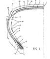
- a pneumatic tyre for vehicle wheels in accordance with the present invention has been generally identified with reference numeral 1.
- structural element of the tyre it is intended any tyre part made of elastomer material such as the tread band, sidewalls, sidewall inserts, fillers, liner and/or under-liner, or a portion thereof, or also the assembly formed of two or more of said parts or portions thereof.
- Tyre 1 essentially comprises a carcass structure 2 of a substantially toroidal conformation, and structural elements of elastomer material 5, 28, 29, 30 associated with the carcass structure 2, as better described in the following.
- the carcass structure 2 may for example comprise a pair of annular anchoring structures 3, integrated into the regions usually identified as “beads” and each, for example, consisting of at least one substantially circumferentiaL annular insert 4, currently referred to as "bead core” and formed of one or more rubber-coated cords or equivalent reinforcing thread elements incorporated in an elastomer matrix.
- An elastomer filler 5 can be applied to the bead core 4, at a radially external position.
- the end flaps 6a of at least one carcass ply 6 comprising textile or metallic rubber-coated cords or equivalent reinforcing thread elements incorporated in an elastomer matrix and extending transversely of the circumferential extension of tyre 2, possibly following a predetermined inclinat ion, from one of the annular anchoring structures 3 to the other.
- the carcass structure 2 has a layer of substantially airtight elastomer material generally referred to as "liner" (not shown) at a radially internal position.
- belt layers 7a, 7b comprising metallic or textile rubber-coated cords, or equivalent reinforcing thread- elements incorporated in an elastomer matrix, suitably inclined to the circumferential extension of the tyre preferably following crossed orientations between a belt layer and the other, as well as a possible outer belting layer (not shown) comprising one or more cords circumferentially wounds into coils disposed in axial side by side relationship around the belt layers 7a, 7b.
- the assembly of the belt layers 7a, 7b and the possible outer belting layer defines a so-called belt structure generally denoted at 7, of substantially cylindrical annular conformation, applied to the carcass structure 3 at a radially external position.
- the belt structure 7, while described as a distinct component is considered (when not expressly stated in a different manner) as an integral part of the carcass structure 2.
- a tread band 28 circumferentially applied to the belt structure 7 at a radially external position, and a pair of sidewalls 29 laterally applied to the carcass structure 2, on opposite sides.
- auxiliary support inserts 30, of the so-called "sidewall insert” type for example can be also provided; they are applied either close to the sidewalls 29 internally of the carcass ply 6, as shown by way of example in Fig. 1 , or between two paired carcass plies or also at a position axially external to the carcass structure 2.
- Tyre 1 lends itself to be manufactured by a manufacturing apparatus essentially comprising devices designed to form the carcass structure 2 and devices for associating with the carcass structure 2, the tread band 28, sidewalls 29, possible auxiliary inserts 30, said liner and/or other structural elements of elastomer material co-operating in forming tyre 1.
- reference numeral 31 denotes a unit for manufacturing structural elements, which unit is part of the devices for associating the structural elements of elastomer material with the carcass structure 2.
- the other components of the apparatus are not shown, because they can be made in any convenient manner.
- the devices for manufacturing tyre 1 may usually comprise a manufacturing line (not shown), in which the carcass structures 2 are obtained, for example, through assembling of carcass plies 6, anchoring structures 3 and/or other parts consisting of semifinished products coming from preceding work and storage steps. Assembling of said parts can be carried out on a so-called “building drum” of the "unistage” type suitable for manufacturing tyres according to a known process currently referred to as “unistage process”; or said assembling can take place on a so-called “first-stage” drum operating in combination with a so-called “shaping drum” suitable for manufacturing tyres according to a known process currently referred to as "two- stage process".
- a belt-forming line comprising devices for making the belt layer or layers 7a, 7b, and devices for transferring the belt structure 7 to a coaxially centred position on the unistage drum or the shaping drum so as to associate the belt structure 7 at a radially external position with the carcass structure 2 when the latter, first made in the form of a cylindrical sleeve, is shaped into a toroidal configuration.
- the carcass structure 2 and/or the respective belt structure 7 can be formed on at least one forming support that, through one or more robotized arms or other suitable devices, is sequentially brought to interact with one or more work stations located along the manufacturing line, to directly form on the forming support itself, the carcass ply 6, annular anchoring structures 3, belt layers 7a, 7b and/or other constituent elements of tyre 1 through laying of elementary components such as rubber-coated cords, strips of rubber-coated cords and/or elongated elements of elastomer material, as described for example in document US 6,457,504 in the name of the same. Applicant.
- elastomer material in tyre 1 such as the tread band 28, sidewalls 29, auxiliary inserts 30, liner, or at least one of them, are preferably made by winding at least one continuous strip-like element of elastomer material into contiguous circumferential coils around a forming support 18, as described in document WO2004/041522 in the name of the same Applicant, for example.
- the forming support 18 can consist of a rigid drum conforming in shape to the inner surface extension of the tyre or having another selected configuration depending on the geometrical features of the structural element to be obtained.
- the forming support 18 can be represented by the carcass ply 6 possibly in turn disposed on a rigid drum, or by other component of the carcass structure 2, such as the belt structure 7, previously associated with the carcass structure 2 itself or not.
- the liner, possible auxiliary inserts 30 and/or other structural elements disposed at the inner surfaces of tyre 1, or to be applied to the carcass structure 2 at a second time can be directly made on a forming support 18 in the form of a rigid drum.
- Other structural elements such as the sidewalls 29 can be directly made against the side surfaces of the carcass ply 6.
- the tread band 28 can in turn be made at a radially external position to the carcass structure 2 and more specifically on the belt structure 7, before or after assembling of said belt structure with the carcass structure 2.
- At least one of the structural elements 5, 28, 29, 30 of elastomer material can be made with the aid of the above mentioned unit 31.
- each structural element 5, 28, 29, 30 can consist of at least one first component 8 of a first elastomer material, and one second component 9 of a second elastomer material different from the first elastomer material.
- the first and second components 8, 9 are advantageously coupled at an undulated interface profile 10 defining mechanical-engagement elements 10a between said two components 8, 9.
- the first elastomer material composing component 8 consists of a blend based on natural rubber or in any case a blend co-crosslinkable with the elastomer matrix used in making the carcass structure and/or the belt layers.
- the second elastomer material constituting the second component 9 can in turn consist of a material having any composition adapted to give the component the desired properties.
- the second component 9 located at an axially external position to the first component can advantageously consist of a polymeric base comprising ethylenepropylene-diene (EPDM) rubbers, polyurethane rubbers, butyl rubbers or mixtures thereof, so as to achieve satisfactory properties of resistance to ageing, easy capability of also printing coloured inscriptions, brightness or other desired features in surface appearance.
- EPDM ethylenepropylene-diene
- the second component 9 axially positioned internally of the first component can advantageously comprise a butadiene rubber-based blend, so as to achieve satisfactory properties of resistance to fatigue and low hysteresis.
- the carcass structure 2 be made with use of an airtight elastomer material, of a butyl rubber-based blend for example, the first elastomer material composing component 8, located at a radially internal position, can use a butyl rubber-based blend too, or in any case a blend co-crosslinkable with the elastomer matrix used in manufacturing the carcass structure 2 (and/or the belt layers 7a, 7b).
- the second elastomer material constituting the second component 9, placed at a radially external position to the first component can advantageously consist of a blend based on a natural or synthetic rubber (polybutadiene or butadiene-styrene copolymers) so as to ensure satisfactory qualities of roadholding and resistance to abrasion.
- a natural or synthetic rubber polybutadiene or butadiene-styrene copolymers
- the liner could be made in the same manner, i.e. making the first radially internal component 8 with an airtight blend, based on butyl rubber for example, and the second component 9 that in this case would form the so-called under-liner, with a compatible blend, i.e. a blend adapted to be co-crosslinked with the blend used for the remaining part of the carcass structure radially and axially external to the liner/under-liner assembly.
- a compatible blend i.e. a blend adapted to be co-crosslinked with the blend used for the remaining part of the carcass structure radially and axially external to the liner/under-liner assembly.
- each structural element of tyre 1 it is possible to use the most appropriate materials for obtaining the desired physical and operational features, without impairing the anchoring stability of the different components during use.
- the first component 8 can advantageously extend over the whole extension of the respective component as shown by way of example with reference to the tread band 28, even if it is also possible for the second component 9 to extend limitedly to a desired surface portion of the first component 8, as shown in connection with the sidewalls 29 and auxiliary inserts 30.
- the wave pitch of the interface profile it is intended the distance P measured in an axial direction in right section between the median points of two consecutive waves.
- the median point of each wave is the mean point of segment "n" joining the opposite radially inner ends of said wave.
- the line Z on which value P is indicated is parallel to the geometric rotation axis X of the forming support 18 and therefore represents the axial direction.
- the radial direction E is indicated perpendicularly to line Z.
- the wave height H is preferably equal to or higher than one tenth of, and preferably higher than half the wave pitch P, so as to obtain effective mechanical-engagement elements 10a also in the absence of undercuts.
- the wave height H is as high as about two times the value of the wave pitch P.
- the waves defining the undulated profile 10 can have an extension, identifiable by the bisecting line K of the vertex of each wave, which is inclined to a direction Q normal to a median line L of the extension of the undulated profile itself, even to a greater extent than as shown in Fig. 2 .
- the inclination angle ⁇ included between said bisecting line K and the perpendicular Q to the median line L is in the range of about 30° to about 88°, and more preferably between about 60° and about 85°.
- a suitable value of the inclination angle ⁇ allows an efficient coupling between the first and second components to be ensured even when the structural element of which they are part has a very restricted extension.
- the complementary mechanical-engagement elements 10a defined by the interface profile 10 may be provided to have portions 10b of mutual undercut constraint, as shown in Fig. 7 .
- a third component of elastomer material 11 may be further provided, said component being disposed at a radially internal position to the first component 8 and being co-crosslinked with the elastomer material forming the first component.
- a fourth component of elastomer material 12 may be also arranged at a position radially external to the second component 9, said fourth component being cross-linked with the elastomer material belonging to at least the second component itself.
- each structural element 28, 2 9, 30 by unit 31 involves preparation of a first elongated element 13 and a second elongated element 14 made of the first and second raw elastomer materials, respectively.
- the first and second elongated elements obtained by extrusion and fed from a first 15 and a second 16 extruders respectively, or other feeding members, are guided to at least one roller 17 or other member carrying out laying of them on a deposition surface 18a of the forming support 18.
- the forming support 18 is preferably supported by a robotized arm 19 only partly shown as it is already known from document WO 00/35666 A1 in the name of the same Applicant.
- the robotized arm 19 is equipped with a motor or other rotatory driving devices giving the forming support 18 a circumferential-distribution rotatory motion around the geometric rotation axis X thereof, by - effect of which a circumferential distribution of the elongated elements 13, 14 laid by the feeding roller 17 on the deposition surface 18a is caused.
- translational driving devices associated with the robotized arm 19 move the forming support 18 in front of the feeding roller 17 with controlled relative displacements of transverse distribution, so that the first and second elongated elements 13, 14 are laid on the deposition surface 18a in the form of coils wound around the geometric axis X of the forming support 18.
- the first and second elongated elements 13, 14 are guided, by effect of the feeding roller 17 or other suitable members, in mutually converging directions towards a point of mutual coupling in which the elongated elements themselves meet and adhere to each other forming a continuous strip-like element 20 that is laid and distributed on the forming support 18 as above described.
- the coupling point of the elongated elements 13, 14 is coincident with the application of same to the forming support 18 by the feeding roller 17.
- said elongated elements 13, 14 can be also guided in such a manner as to cause coupling of same at a point upstream of the forming support 18.
- the continuous strip-like element 20 should come from a supply reel, used in a storage step of the strip-like element itself after carrying out mutual coupling of the elongated elements 13, 14.
- the elongated elements 13, 14 can-be co-extruded and directly coupled in the extrusion head of a single extruder 26 ( Fig. 3a ) so that the strip-like element 20 is directly generated at the extruder outlet.
- the elongated elements 13, 14 can be simultaneously laid on the forming support 18 at points A, B that are mutually spaced apart in a circumferential direction.
- the coupling point between the elongated elements is coincident with the application point of the second elongated element 14 onto the forming support 18.
- the elongated elements 13, 14 are mutually coupled in such a manner that, when coupling has occurred, each of them has a base portion 21, 22 in contact with the base portion of the other elongated element.
- at least one of the elongated elements 13, 14 may have an apex 23, 24 projecting from the base portion 21, 22, in a direction transverse to the direction of mutual alignment of the base portions themselves, denoted at D in said figures.
- the elongated elements 13, 14 that can have a conformation substantially identical with each other, are coupled at mutually offset positions in a plane transverse to the mutual alignment direction D of the base portions 21, 22, so that each of them has a respective apex 23, 24 projecting in the opposite direction with respect to the apex of the other elongated element.
- the mutual positioning of the elongated elements 13, 14 and/or orientation of the continuous strip-like element 20 formed by them is controlled in such a manner that, on coming close to the deposition surface 18a, the apex 23 of the first elongated element 13 is turned towards the forming support 18.
- apex 23 of the first elongated element 13 during application is deformed and it consequently bends towards the base portion 22 of the second elongated element 14, taking an interposed position between the second elongated element 14 and the forming support 18 so as to avoid a direct contact of the second elastomer material against the deposition surface 18a.
- the coils disposed consecutively in side by side relationship and formed by the first elongated element 13, by effect of bending of apex 23 as above described give rise to a continuous layer made up of the elastomers material, that extends over the whole deposit ion surface 18a.
- Apex 24 of the second elongated element 14 is oriented radially away from the deposition surface 18a exhibited by the forming support 18 and can be turned up against the base portion 21 of the first elongated element 13, so that the coils in side by side relationship formed by the second elongated element 14 cause formation of a continuous layer made up of the second elastomer material.
- turning up of apex 24 of the second elongated element 14 can be assisted by a roller or other auxiliary applicator member 25, operating downstream of the feeding roller 17.
- the base portions 21, 22 of the first and second elongated elements 13, 14 generate the interface profile 10 between the first and second components.
- first and second elongat ed elements 13, 14 can be preceded by application of the third component 11 made of the same blend as that of the elongated element 13 or, in any case, a blend co-crosslinkable with the first elastomer material forming the first elongated element 13.
- Formation of this third component can take place in the same manner as previously described with reference to laying of the continuous strip-like element 20, i.e. through application of a continuous elongated element of elastomer material coming from an extruder for example and formed into coils disposed consecutively in side by side relationship to cover the deposition surface 18a of the forming support 18.
- fourth component 12 may be also carried out, said component being made of a material co-crosslinkable with the second elastomer material forming the second elongated element 14.
- Formation of the fourth component 12 too can be carried out by applying onto the forming support 18, a fourth elongated element of elastomer material corning from an extruder and formed into coils disposed consecutively in side by side relationship.
- the third and fourth elongated elements can be advantageously produced either by the same extruders 15, 16 used for formation of the first and second elongated elements 13, 14, or by specific extruders dedicated thereto.
- third and/or fourth elastomer components 11, 12 arrangement of apices 23, 24 projecting from the first and second elongated elements 13, 14 respectively may appear to be superfluous, as said third and fourth components can be co-crosslinkable with the material forming the base portions 21, 22 of the elongated elements 13, 14, respectively.
- the elongated elements 13, 14 can have a conformation with a substantially flattened cross-section.
- an interface profile 10 as shown in Fig. 2 is preferably obtained, in which the wave height H is greatly higher than the wave pitch, so that the hills and valleys of the undulated profile will cause formation of the mechanical-engagement elements.
- the elongated elements 13, 14 can advantageously have a cross-section profile of triangular conformation.
- the base portions 21, 22 of the coupled elongated elements 13, 14 give rise to formation of portions 10b with an undercut constraint, in the mechanical-engagement elements 10a.
- the same effect is achieved using elongated elements 13, 14 having a trapezoidal cross-section profile.
- the tyre When formation of the structural elements 28, 29, 30 co-operating in the manufacture of tyre 1 together with the carcass structure 2, has been completed, the tyre itself lends itself to be introduced into a mould to be submitted to a moulding and vulcanisation step that can be carried out in any convenient manner.
- the tyre in reference lends itself to be made in a simple and cheap manner, utilising machinery and equipment already provided in modern tyre-production cycles in which the structural elements of elastomer material are obtained by winding up elongated elements of raw elastomer material into coils disposed in side by side relationship on a forming support, as described in document WO 00/35666 A1 in the name of the same Applicant.
Landscapes
- Engineering & Computer Science (AREA)
- Mechanical Engineering (AREA)
- Tyre Moulding (AREA)
- Tires In General (AREA)
- Extrusion Moulding Of Plastics Or The Like (AREA)
Claims (59)
- Luftreifen für Fahrzeugräder mit:- einer Karkassenstruktur (2) mit verstärkenden Faserelementen, die in eine Elastomermatrix eingebettet sind,- Strukturelementen aus Elastomermaterial (28, 29, 30), die der Karkassenstruktur (2) zugeordnet sind,
wobei wenigstens eines der Strukturelemente (28, 29, 30) aufweist:- wenigstens eine erste Komponente (8), die aus einem ersten Elastomermaterial gebildet ist,- und wenigstens eine zweite Komponente (9), die aus einem zweiten Elastomermaterial, das von dem ersten Elastomermaterial verschieden ist, gebildet ist,
wobei die erste und zweite Komponente (8, 9) ein gewelltes Grenzflächenprofil (10) aufweisen,
wobei das Grenzflächenprofil (10) mechanische Eingriffselemente (10a) zwischen der ersten und zweiten Komponente (8, 9) definiert,
dadurch gekennzeichnet, dass das gewellte Grenzflächenprofil (10) ein durchgehendes streifenartiges Element (20) aufweist, das sich um die geometrische Achse (X) des Reifens gemäß Umfangsspiralen in einer nebeneinander angeordneten Beziehung herum erstreckt,
bei der das durchgehende streifenartige Element (20) ein erstes und ein zweites längliches Element (13, 14) aufweist, die miteinander entlang ihrer Längserstreckung gekoppelt sind. - Reifen nach Anspruch 1, bei dem eine Lauffläche (28), die auf der Karkassenstruktur (2) an einer radial äußeren Position aufgebracht ist, die zweite Komponente (9) an einer im Vergleich zu der ersten Komponente (8) radial äußeren Position vorgesehen hat.
- Reifen nach Anspruch 1 oder 2, bei dem ein Paar Seitenwände (29) an der Karkassenstruktur (2) an seitlich gegenüberliegenden Positionen angebracht ist, wobei wenigstens eine der Seitenwände (29) die zweite Komponente (9) an einer Position vorgesehen hat, die axial außerhalb der ersten Komponente (8) ist.
- Reifen nach einem oder mehreren der vorherigen Ansprüche, bei dem ein Paar Hilfslagereinsätze (30) der Karkassenstruktur (2) zugeordnet ist, wobei wenigstens eines der Hilfslagereinsätze (30) die zweite Komponente (9) an einer bezüglich der ersten Komponente (8) axial äußeren Position vorgesehen hat.
- Reifen nach einem oder mehreren der vorherigen Ansprüche, bei dem ein Auskleidungsmittel und ein Unterauskleidungsmittel an der Karkassenstruktur (2) an einer radial inneren Position angebracht sind, wobei das Unterauskleidungsmittel die zweite Komponente (9) an einer im Vergleich zu der ersten Komponente (8), die das Auskleidungsmittel bildet, radial äußeren Position aufweist.
- Reifen nach einem oder mehreren der vorherigen Ansprüche, bei dem das Grenzflächenprofil (10) eine Wellenhöhe (H) und einen Wellenabstand (P) aufweist, bei denen die Wellenhöhe (H) größer oder gleich einem Zehntel des Wellenabstands (P) ist.
- Reifen nach Anspruch 6, bei dem die Wellenhöhe (H) größer ist als die Hälfte des Wellenabstands (P).
- Reifen nach Anspruch 6, bei dem die Wellenhöhe (H) größer als der vierfache Wellenabstand (P) ist.
- Reifen nach einem oder mehreren der vorherigen Ansprüche, bei dem die mechanischen Eingriffselemente (10a) Abschnitte einer gegenseitigen hinterschnittenen Verschränkung (10b) aufweisen.
- Reifen nach einem oder mehreren der vorherigen Ansprüche, bei dem das gewellte Grenzflächenprofil (10) mehrere Wellen mit einer geneigten Erstreckung in einer Richtung senkrecht zu einer Mittellinie (L) der Erstreckung des gewellten Profils aufweist.
- Reifen nach Anspruch 10, bei dem jede Welle einen Neigungswinkel (α) zwischen einer Winkelhalbierenden (K) eines Scheitels der Welle und der Richtung (Q), die senkrecht zu der Mittellinie (L) ist, aufweist, der zwischen ungefähr 30° und ungefähr 88° liegt.
- Reifen nach Anspruch 11, bei dem der Neigungswinkel (α) zwischen ungefähr 60° und ungefähr 85° liegt.
- Reifen nach einem oder mehreren der vorherigen Ansprüche, wobei mit der ersten Komponente (8) eine dritte Komponente (11) aus Elastomermaterial, das wenigstens mit dem ersten Elastomermaterial vernetzt ist, gekoppelt ist.
- Reifen nach Anspruch 13, wobei mit der zweiten Komponente (9) eine vierte Komponente (12) aus Elastomermaterial, das mit dem ersten und/oder zweiten Elastomermaterial vernetzt ist, gekoppelt ist.
- Reifen nach einem oder mehreren der vorherigen Ansprüche, bei dem sich die zweite Komponente (9) entlang wenigstens eines Oberflächenabschnitts der ersten Komponente (8) erstreckt.
- Reifen nach einem oder mehreren der vorherigen Ansprüche, bei dem das erste Elastomermaterial mit der Elastomermatrix der Karkassenstruktur (2) quervernetzt ist.
- Verfahren zum Herstellen eines Reifens für Fahrzeugräder mit den Schritten:- des Ausbildens einer Karkassenstruktur (2) mit verstärkenden Fadenelementen, die in eine Elastomermatrix eingebettet sind,- des Zuordnens von Strukturelementen (28, 29, 30) aus Elastomermaterial zu der Karkassenstruktur (2),
bei dem der Schritt des Zuordnens der Strukturelemente (28, 29, 30) aus Elastomermaterial zu der Karkassenstruktur (2) als Schritte aufweist:- das Vorbereiten wenigstens eines länglichen Elements (13) mit einem ersten unverarbeiteten Elastomermaterial und wenigstens eines zweiten länglichen Elements (14) mit einem zweiten unverarbeiteten Elastomermaterial mit einer Zusammensetzung, die von derjenigen des ersten Elastomermaterials verschieden ist,- das Legen des ersten länglichen Elements (13) auf ein formendes Lager (18) in Spiralen, die um eine geometrische Achse (X) des formenden Lagers (18) gewunden sind, um somit eine erste Komponente (8) des Strukturelements (28, 29, 30) zu bilden,- das Legen des zweiten länglichen Elements (14) auf das formende Lager (18) in Spiralen, die um die geometrische Achse (X) des formenden Lagers (18) gewunden sind, um somit eine zweite Komponente (9) des Strukturelements (28, 29, 30) zu bilden, die der ersten Komponente (8) überlagert ist,- das Aushärten des Reifens,
dadurch gekennzeichnet, dass ein Schritt des gegenseitigen Koppelns der ersten und zweiten länglichen Elemente (13, 14) entlang ihrer Längserstreckung erzielt wird, um ein durchgehendes streifenartiges Element (20) zu bilden, das um die geometrische Achse (X) des formenden Lagers (18) gemäß Umfangsspiralen in einer nebeneinander angeordneten Beziehung während des Legeschritts gewunden wird, wobei ein gewelltes Grenzflächenprofil (10) zwischen der ersten und der zweiten Komponente (8, 9) erzielt wird, wobei das Grenzflächenprofil (10) mechanische Eingriffselemente (10a) zwischen der ersten und zweiten Komponente definiert. - Verfahren nach Anspruch 17, bei dem das Legen der ersten und zweiten länglichen Elemente (13, 14) an einer radial äußeren Position in Bezug auf die Karkassenstruktur (2), die vorher auf das formende Lager gelegt wurde, ausgeführt wird, um eine Lauffläche (28) des Reifens (1) zu bilden.
- Verfahren nach Anspruch 17 oder 18, ferner mit den Schritten des Legens wenigstens einer Gürtelschicht (7a, 7b) und des Zuordnens der wenigstens einen Gürtelschicht (7a, 7b) zu der Karkassenstruktur (2), wobei das Legen der ersten und zweiten länglichen Elemente (13, 14) an einer radial in Bezug auf die wenigstens eine Gürtelschicht (7a, 7b) äußeren Position vor oder nach dem Zuordnen der Gürtelschicht zu der Karkassenstruktur (2) ausgeführt wird, um eine Lauffläche (28) des Reifens (1) zu bilden.
- Verfahren nach einem der Ansprüche 17 bis 19, bei dem das Legen der ersten und zweiten länglichen Elemente (13, 14) seitlich in Bezug auf die Karkassenstruktur (2) ausgeführt wird, um wenigstens eine Seitenwand (29) des Reifens (1) zu bilden.
- Verfahren nach einem der Ansprüche 17 bis 20, bei dem das Legen der ersten und zweiten länglichen Elemente (13, 14) an einer in Bezug auf das formende Lager (18) axial äußeren Position ausgeführt wird, um wenigstens einen Lagereinsatz (30) vor dem Legen der Karkassenstruktur (2) auf das formende Lager (18) zu bilden, um den wenigstens einen Lagereinsatz (30) seitlich in Bezug auf das Innere der Karkassenstruktur (2) selbst anzubringen.
- Verfahren nach einem der Ansprüche 17 bis 21, bei dem das Grenzflächenprofil (10) eine Wellenhöhe (H) und einen Wellenabstand (P) aufweist, bei denen die Wellenhöhe (H) wenigstens so hoch wie ein Zehntel des Wellenabstands (P) ist.
- Verfahren nach Anspruch 22, bei dem die Wellenhöhe (H) größer ist als die Hälfte des Wellenabstands (P).
- Verfahren nach Anspruch 22, bei dem die Wellenhöhe (H) größer ist als der vierfache Wellenabstand (P).
- Verfahren nach einem oder mehreren der Ansprüche 17 bis 24, bei dem das gewellte Grenzflächenprofil (10) mehrere Wellen mit einer geneigten Erstreckung in einer Richtung (Q) senkrecht zu einer Mittellinie (L) der Erstreckung des gewellten Profils aufweist.
- Verfahren nach Anspruch 25, bei dem jede Welle einen Neigungswinkel (α) zwischen einer Winkelhalbierenden (K) eines Scheitels der Welle und der Richtung (Q) senkrecht zu der Mittellinie (L) aufweist, der zwischen ungefähr 30° und ungefähr 88° liegt.
- Verfahren nach Anspruch 26, bei dem der Neigungswinkel (α) zwischen ungefähr 60° und ungefähr 85° liegt.
- Verfahren nach einem oder mehreren der Ansprüche 17 bis 27, bei dem die mechanischen Eingriffselemente (10) Abschnitte von einer gegenseitigen hinterschnittenen Verschränkung (10b) aufweisen.
- Verfahren nach einem oder mehreren der Ansprüche 17 bis 28, bei dem wenigstens eines der ersten und zweiten länglichen Elemente (13, 14) eine abgeflachte Querschnittsgestalt aufweist.
- Verfahren nach einem oder mehreren der Ansprüche 17 bis 28, bei dem wenigstens eines der ersten und zweiten länglichen Elemente (13, 14) eine im Wesentlichen dreieckige Querschnittsgestalt aufweist.
- Verfahren nach einem oder mehreren der Ansprüche 17 bis 28, bei dem wenigstens eines der ersten und zweiten länglichen Elemente (13, 14) eine im Wesentlichen trapezförmige Querschnittsgestalt aufweist.
- Verfahren nach einem oder mehreren der Ansprüche 17 bis 31, bei dem der Kopplungsschritt vor den Legeschritten ausgeführt wird.
- Verfahren nach einem oder mehreren der Ansprüche 17 bis 31, bei dem das Vorbereiten des durchgehenden streifenartigen Elements (20) als Schritte aufweist:- das Zuführen des ersten länglichen Elements (13) durch ein erstes Zuführelement (15),- das Zuführen des zweiten länglichen Elements (14) durch ein zweites Zuführelement (16) gleichzeitig mit dem Zuführen des ersten länglichen Elements (13),- das Leiten des ersten und zweiten länglichen Elements (13, 14) in gegenseitig zusammenlaufende Richtungen zu einem Punkt des gegenseitigen Koppelns hin.
- Verfahren nach Anspruch 33, bei dem das Zuführen des ersten und zweiten länglichen Elements (13, 14) durch Extrusion jeweils durch erste und zweite Extruder (15, 16) stattfindet, die Teil der ersten und zweiten Zuführelemente sind.
- Verfahren nach einem oder mehreren der Ansprüche 17 bis 31, bei dem das durchgehende streifenartige Element (20) durch Koextrusion der ersten und zweiten länglichen Elemente (13, 14) durch den gleichen Extruder (26) hergestellt wird.
- Verfahren nach einem oder mehreren der Ansprüche 17 bis 31, bei dem der Kopplungsschritt gleichzeitig mit dem Aufwickeln des streifenartigen Elements (20) auf das formende Lager (18) an einem Punkt des gegenseitigen Koppelns zwischen den länglichen Elementen (13, 14), die an dem formenden Lager (18) angeordnet sind, ausgeführt wird.
- Verfahren nach einem der Ansprüche 17 bis 31, bei dem der Kopplungsschritt gleichzeitig mit dem Aufwickeln des streifenartigen Elements (20) auf das formende Lager (18) an einem Punkt des gegenseitigen Koppelns zwischen den länglichen Elementen (13, 14), die dem formenden Lager (18) vorgelagert angeordnet ist, ausgeführt wird.
- Verfahren nach einem oder mehreren der Ansprüche 17 bis 35, bei dem das erste und das zweite längliche Elemente (13, 14) gleichzeitig auf das formende Lager (18) an Punkten (A, B) gelegt werden, die in einer Umfangsrichtung voneinander beabstandet sind.
- Verfahren nach einem oder mehreren der Ansprüche 17 bis 38, wobei im Anschluss an den Kopplungsschritt jedes der länglichen Elemente (13, 14) einen Basisabschnitt (21, 22) aufweist, der einstückig mit einem Basisabschnitt des anderen länglichen Elements ist, wobei wenigstens eines der länglichen Elemente (13, 14) eine Spitze (23, 24) aufweist, die von dem Basisabschnitt (21, 22) quer zu einer Richtung der gegenseitigen Ausrichtung (D) der Basisabschnitte (21, 22) hervorragt.
- Verfahren nach Anspruch 39, bei dem die ersten und zweiten länglichen Elemente (13, 14) an gegenseitig versetzten Positionen in einer Querrichtung relativ zu einer Richtung (D) der gegenseitigen Ausrichtung der Basisabschnitte (21) gekoppelt sind, sodass jedes längliche Element (13, 14) die Spitze (23, 24) so aufweist, dass sie in der in Bezug auf die Spitze des anderen länglichen Elements entgegengesetzten Richtung hervorsteht.
- Verfahren nach Anspruch 39 oder 40, bei dem die Spitze (23, 24) eines länglichen Elements (13, 14) in Bezug auf einen Basisabschnitt (21, 22) des anderen länglichen Elements umgebogen ist.
- Verfahren nach einem oder mehreren der Ansprüche 17 bis 41, bei dem das Legen sowohl von dem ersten als auch von dem zweiten länglichen Element (13, 14) als Schritte aufweist:- das Zuführen des länglichen Elements (13, 14) von einem Zuführelement (15, 16, 17), das benachbart zu dem formenden Lager vorgesehen ist, zum Aufbringen des länglichen Elements auf das Lager selbst,- das Versetzen des formenden Lagers (18) in eine Umfangsverteilungsdrehbewegung um die geometrische Drehachse (X), sodass das längliche Element (13, 14) umfänglich auf dem formenden Lager (18) verteilt wird,- das Ausführen von geregelten relativen Verschiebungen der Querverteilung zwischen dem formenden Lager (18) und dem Zuführelement (15, 16, 17), um die Spiralen auszubilden.
- Verfahren nach einem der Ansprüche 17 bis 42, ferner mit dem Schritt des Aufbringens wenigstens einer dritten Komponente (11) auf das formende Lager (18) vor dem Aufbringen der ersten Komponente (8), wobei die dritte Komponente (11) aus einem Elastomermaterial besteht, das wenigstens mit dem ersten Elastomermaterial vernetzbar ist.
- Verfahren nach einem oder mehreren der Ansprüche 17 bis 43, ferner mit dem Schritt des Aufbringens einer vierten Komponente (12) im Anschluss an das Aufbringen der zweiten Komponente (9), wobei die vierte Komponente (12) aus einem Elastomermaterial besteht, das wenigstens mit dem zweiten Elastomermaterial quervernetzbar ist.
- Verfahren nach einem oder mehreren der Ansprüche 17 bis 44, bei dem das erste Elastomermaterial mit der Elastomermatrix der Karkassenstruktur (2) quervernetzbar ist.
- Vorrichtung zum Herstellen von Luftreifen für Fahrzeugräder mit:- Einrichtungen, die dafür vorgesehen sind, um eine Karkassenstruktur (2) mit verstärkenden Fadenelementen auszubilden, die in eine Elastomermatrix eingebettet sind,- Einrichtungen (31) zum Zuordnen der Strukturelemente (28, 29, 30) aus Elastomermaterial zu der Karkassenstruktur (2),- Einrichtungen zum Aushärten des Reifens,
bei dem die Einrichtungen zum Zuordnen der Strukturelemente (28, 29, 30) aus Elastomermaterial zu der Karkassenstruktur (2) wenigstens eine Einheit (31) zum Herstellen der Strukturelemente aufweisen,
dadurch gekennzeichnet, dass die Einheit (31) aufweist:- Zuführelemente (15, 16) zum Einbringen wenigstens eines länglichen Elements (13) mit einem ersten unverarbeiteten Elastomermaterial und wenigstens eines zweiten länglichen Elements (14) mit einem zweiten unverarbeiteten Elastomermaterial mit einer Zusammensetzung, die von derjenigen des ersten Elastomermaterials verschieden ist,- Elemente (17, 25) zum Legen der ersten und zweiten länglichen Elemente (13, 14) auf ein formendes Lager (18) in Spiralen, die um eine geometrische Achse (X) des formenden Lagers (18) gewunden sind, um somit eine erste Komponente (8) des Strukturelements (28, 29, 30) und eine zweite Komponente (9) des Strukturelements (28, 29, 30), die der ersten Komponente (8) jeweils überlagert ist, auszubilden,
ferner mit Einrichtungen zum gegenseitigen Koppeln der ersten und zweiten länglichen Elemente (13, 14) entlang ihrer Längserstreckung, um ein durchgehendes streifenartiges Element (20) zu formen,
wobei die Legeelemente (17, 25) zum Aufwickeln des durchgehenden streifenartigen Elements (20) um die geometrische Achse (X) des formenden Lagers (18) gemäß Umfangsspiralen in einer nebeneinander angeordneten Beziehung vorgesehen sind, wobei ein gewelltes Grenzflächenprofil (10) zwischen der ersten und zweiten Komponente (8, 9) erzeugt wird, wobei das Grenzflächenprofil (10) mechanische Eingriffselemente (10a) zwischen der ersten und zweiten Komponente (8, 9) definiert. - Vorrichtung nach Anspruch 46, bei der die wenigstens eine Einheit (31) zum Herstellen von Strukturelementen zum Herstellen von Laufflächen an einer in Bezug auf die Karkassenstruktur (2) radial äußeren Position bestimmt ist.
- Vorrichtung nach Anspruch 46 oder 47, ferner mit Einrichtungen zum Herstellen wenigstens einer Gürtelschicht (7a, 7b) und Einrichtungen zum Zuordnen der wenigstens einen Gürtelschicht (7a, 7b) zu der Karkassenstruktur (2) an einer radial äußeren Position, bei der die wenigstens eine Einheit (31) zum Herstellen von Strukturelementen zum Herstellen von Laufflächen (28) an einer radial äußeren Position in Bezug auf die wenigstens eine Gürtelschicht (7a, 7b) bestimmt ist.
- Vorrichtung nach einem oder mehreren der Ansprüche 46 bis 48, bei der die wenigstens eine Einheit (31) zum Herstellen von Strukturelementen zum Herstellen von Seitenwänden (29), die seitlich in Bezug auf die Karkassenstruktur (2) vorgesehen sind, bestimmt ist.
- Vorrichtung nach einem oder mehreren der Ansprüche 46 bis 48, bei der die wenigstens eine Einheit (31) zum Herstellen von Strukturelementen zum Herstellen von Hilfslagereinsätzen (30) zum Zuordnen mit der Karkassenstruktur (2) bestimmt ist.
- Vorrichtung nach einem oder mehreren der Ansprüche 46 bis 50, bei der die wenigstens eine Einheit (31) zum Herstellen von Strukturelementen aufweist:- ein erstes Zuführelement (15), das zum Zuführen des ersten länglichen Elements (13) eingestellt ist,- ein zweites Zuführelement (16), das zum Zuführen des zweiten länglichen Elements (14) eingestellt ist,- Einrichtungen (17, 25) zum Leiten des ersten und zweiten länglichen Elements (13, 14) in gegenseitige zusammenlaufende Richtungen zu einem gegenseitigen Kopplungspunkt hin.
- Vorrichtung nach Anspruch 51, bei welcher der gegenseitige Kopplungspunkt zwischen den länglichen Elementen (13, 14) an dem formenden Lager (18) angeordnet ist.
- Vorrichtung nach Anspruch 51, bei welcher der gegenseitige Kopplungspunkt zwischen den länglichen Elementen (13, 14) dem formenden Lager (18) vorgelagert angeordnet ist.
- Vorrichtung nach Anspruch 51, bei der die Leiteinrichtungen die ersten und zweiten länglichen Elementen (13, 14) an dem formenden Lager (18) zu Punkten (A, B) leiten, die gegenseitig in einer Umfangsrichtung voneinander beabstandet sind.
- Vorrichtung nach einem oder mehreren der Ansprüche 51 bis 54, bei der das erste und zweite Zuführelement jeweils erste und zweite Extruder (15, 16) aufweisen.
- Vorrichtung nach einem oder mehreren der Ansprüche 46 bis 50, bei der die wenigstens eine Einheit (31) zum Herstellen von Strukturelementen (28, 29, 30) wenigstens einen Extruder (26) zur Koextrusion der ersten und zweiten länglichen Elemente (13, 14) aufweist, um das durchgehende streifenartige Element (20) herzustellen.
- Vorrichtung nach einem oder mehreren der Ansprüche 46 bis 56, bei der die wenigstens eine Einheit (31) zum Herstellen der Strukturelemente (28, 29, 30) aufweist:- wenigstens ein Zuführelement (15, 16, 17), das auf dem formenden Lager (18) zum Aufbringen des wenigstens einen länglichen Elements (13, 14) auf das Lager selbst vorgesehen ist,- Drehantriebseinrichtungen, um das formende Lager (18) in eine Umfangsverteilungsdrehbewegung um die geometrische Drehachse (X) zu versetzen, sodass das längliche Element (13, 14) umfänglich auf dem formenden Lager (18) verteilt wird,- Translationsantriebseinrichtungen, um eine geregelte relative Verschiebung der Querverteilung zwischen dem formenden Lager (18) und dem Zuführelement (15, 16, 17) auszuführen, um die Spiralen zu formen.
- Vorrichtung nach einem oder mehreren der Ansprüche 46 bis 57, bei dem die wenigstens eine Einheit (31) zum Herstellen der Strukturelemente (28, 29, 30) ferner Einrichtungen zum Aufbringen von wenigstens einer dritten Komponente (11) eines Elastomermaterials, das wenigstens mit dem ersten Elastomermaterial quervernetzbar ist, auf das formende Lager (18) aufweist.
- Vorrichtung nach einem oder mehreren der Ansprüche 46 bis 58, bei dem die wenigstens eine Einheit (31) zum Herstellen der Strukturelemente (28, 29, 30) ferner Einrichtungen zum Aufbringen einer vierten Komponente (12) aus Elastomermaterial, das wenigstens mit dem zweiten Elastomermaterial quervernetzbar ist, auf das formende Lager (18) aufweist.
Applications Claiming Priority (1)
| Application Number | Priority Date | Filing Date | Title |
|---|---|---|---|
| PCT/IT2004/000592 WO2006046259A1 (en) | 2004-10-27 | 2004-10-27 | Pneumatic tyre for vehicle, method and apparatus for its manufacture |
Publications (2)
| Publication Number | Publication Date |
|---|---|
| EP1817177A1 EP1817177A1 (de) | 2007-08-15 |
| EP1817177B1 true EP1817177B1 (de) | 2011-08-24 |
Family
ID=34959428
Family Applications (1)
| Application Number | Title | Priority Date | Filing Date |
|---|---|---|---|
| EP04791926A Expired - Lifetime EP1817177B1 (de) | 2004-10-27 | 2004-10-27 | Luftreifen für fahrzeug, verfahren und vorrichtung zu seiner herstellung |
Country Status (7)
| Country | Link |
|---|---|
| US (1) | US20090101264A1 (de) |
| EP (1) | EP1817177B1 (de) |
| KR (1) | KR101146236B1 (de) |
| CN (2) | CN101052537B (de) |
| AT (1) | ATE521486T1 (de) |
| BR (1) | BRPI0419154B1 (de) |
| WO (1) | WO2006046259A1 (de) |
Families Citing this family (7)
| Publication number | Priority date | Publication date | Assignee | Title |
|---|---|---|---|---|
| FR2924376B1 (fr) * | 2007-12-03 | 2009-11-20 | Michelin Soc Tech | Dispositif et procede de realisation d'une bande de roulement |
| JP4989449B2 (ja) * | 2007-12-25 | 2012-08-01 | 横浜ゴム株式会社 | 空気入りタイヤの製造方法及び空気入りタイヤ |
| KR101325396B1 (ko) * | 2012-08-21 | 2013-11-08 | 한국타이어 주식회사 | 차량용 타이어의 트레드 및 그를 포함하는 차량용 타이어 |
| JP6091006B2 (ja) * | 2013-09-30 | 2017-03-08 | 東洋ゴム工業株式会社 | 空気入りタイヤの製造方法及び空気入りタイヤ |
| WO2015150970A1 (en) * | 2014-04-02 | 2015-10-08 | Pirelli Tyre S.P.A. | Method and equipment for controlling a manufacturing process of a component of a tyre for vehicle wheels. |
| JP7560484B2 (ja) | 2019-05-30 | 2024-10-02 | ピレリ・タイヤ・ソチエタ・ペル・アツィオーニ | 車両ホイール用のタイヤを構築するためのプロセス及び装置、並びにそれから得られるタイヤ |
| IT202000015748A1 (it) * | 2020-06-30 | 2021-12-30 | Bridgestone Europe Nv Sa | Metodo e unita' di applicazione per applicare un materiale fonoassorbente in una cavita' interna di uno pneumatico |
Family Cites Families (35)
| Publication number | Priority date | Publication date | Assignee | Title |
|---|---|---|---|---|
| US469824A (en) * | 1892-03-01 | Gas-burner | ||
| US1603312A (en) * | 1925-05-28 | 1926-10-19 | Goodyear Tire & Rubber | Method of and apparatus for manufacturing inner tubes |
| US2198008A (en) * | 1937-10-08 | 1940-04-23 | Us Rubber Co | Tear resisting rubber sheeting |
| DE1228525B (de) | 1958-03-06 | 1966-11-10 | Lemfoerder Kunststoff G M B H | Kraftfahrzeugreifen |
| US2996095A (en) * | 1958-11-19 | 1961-08-15 | Firestone Tire & Rubber Co | Laminated article |
| US3464090A (en) * | 1967-09-26 | 1969-09-02 | Nrm Corp | Tire curing press |
| DE2160337A1 (de) | 1971-12-06 | 1973-06-07 | Continental Gummi Werke Ag | Fahrzeugluftreifen |
| US4405007A (en) * | 1977-06-27 | 1983-09-20 | The Goodyear Tire & Rubber Company | Pneumatic safety tire |
| US4478266A (en) * | 1982-09-17 | 1984-10-23 | The Goodyear Tire & Rubber Company | Composite tread having good traction and reduced rolling resistance upon wear |
| EP0111100B1 (de) * | 1982-10-16 | 1990-08-22 | Grace Service Chemicals GmbH | Anwendung eines Trennmittelfilms bei der Vulkanisation von Gummiartikeln |
| DE3325017C2 (de) * | 1983-07-11 | 1985-11-28 | Continental Gummi-Werke Ag, 3000 Hannover | Preßkopf zum Herstellen von flachen zusammenhängenden Profilsträngen aus plastischen Kautschuk- oder Kunststoffmischungen verschiedener Zusammensetzung |
| DE3428368A1 (de) * | 1984-08-01 | 1986-02-13 | Continental Gummi-Werke Ag, 3000 Hannover | Unvulkanisierter laufstreifen fuer fahrzeugluftreifen |
| US4704176A (en) | 1984-12-19 | 1987-11-03 | The Goodyear Tire & Rubber Company | Method of bonding polyurethane to cured rubber |
| US5221406A (en) * | 1986-09-17 | 1993-06-22 | Compagnie Generale Des Etablissements Michelin | Apparatus for manufacturing a tire by the laying of rubber products onto a rotating core |
| US5211898A (en) | 1988-07-27 | 1993-05-18 | Tomy Machinery Manufacturing Co., Ltd. | Method and apparatus for feeding a plurality of molten resin jet streams into T die |
| US5250142A (en) * | 1990-07-27 | 1993-10-05 | Longwood Elastomers, Inc. | Rubber surface having non-stick ply turn-up bladder |
| ES2090459T3 (es) * | 1991-11-15 | 1996-10-16 | Pirelli | Neumatico autoportante para ruedas de vehiculos a motor que incorporan inserciones elasticas en los flancos. |
| DE4419299A1 (de) | 1994-06-01 | 1995-12-07 | Sp Reifenwerke Gmbh | Fahrzeugluftreifen |
| JP2962658B2 (ja) * | 1994-08-22 | 1999-10-12 | 住友ゴム工業株式会社 | 空気入りチューブレスタイヤ |
| CA2140999A1 (en) * | 1994-11-07 | 1996-05-08 | Jennifer Leigh Gabor | Triplex tread |
| DE69704813T2 (de) * | 1996-07-11 | 2001-10-04 | Bridgestone Corp., Tokio/Tokyo | Luftreifen |
| IT1290520B1 (it) * | 1997-04-03 | 1998-12-04 | Pirelli | Metodo ed apparato di estrusione per realizzare fasce battistrada per pneumatici di veicoli |
| US5939002A (en) * | 1997-04-16 | 1999-08-17 | Michelin Recherche Et Technique S.A. | Apparatus and process for changing a sidewall insert of a tire mold |
| DE19718699C1 (de) * | 1997-05-02 | 1998-05-28 | Continental Ag | Verfahren zur Herstellung eines Fahrzeugluftreifens |
| JP4315526B2 (ja) * | 1998-07-08 | 2009-08-19 | 株式会社ブリヂストン | 帯状未加硫ゴムの積層方法 |
| US6457504B1 (en) * | 1998-07-31 | 2002-10-01 | Pirelli Pneumatici S.P.A. | Carcass structure for vehicle tires |
| US6279633B1 (en) * | 1999-03-23 | 2001-08-28 | The Goodyear Tire & Rubber Company | Tire with EPDM-based component |
| US7153381B2 (en) * | 1999-07-30 | 2006-12-26 | The Goodyear Tire & Rubber Company | Cured applique or label with protective film on arcuate sidewall or tread of pneumatic tire |
| US6458446B1 (en) * | 1999-09-14 | 2002-10-01 | Pureflex, Inc. | Thermoplastic sheet with textured surface for use in composite layered product with interlocking interface and method thereof |
| JP5013636B2 (ja) | 2000-05-24 | 2012-08-29 | 株式会社ブリヂストン | タイヤ構成部材の成形方法 |
| US20030127170A1 (en) * | 2001-06-05 | 2003-07-10 | Alain Cottin | Method for protecting a tire against ozone |
| JP2002355878A (ja) * | 2001-05-30 | 2002-12-10 | Bridgestone Corp | グリーンタイヤの製造方法およびその装置 |
| JP4637412B2 (ja) * | 2001-07-25 | 2011-02-23 | 株式会社ブリヂストン | ゴム成型体の製造方法およびその装置 |
| EP1308257A3 (de) * | 2001-11-02 | 2005-12-28 | Teijin Limited | Reifenvulkanisierbalg und Verfahren zur Reifenherstellung |
| WO2003041941A1 (en) * | 2001-11-12 | 2003-05-22 | Bridgestone Corporation | Production method for unvulcanized rubber member and tire |
-
2004
- 2004-10-27 KR KR1020077009642A patent/KR101146236B1/ko not_active Expired - Fee Related
- 2004-10-27 WO PCT/IT2004/000592 patent/WO2006046259A1/en not_active Ceased
- 2004-10-27 EP EP04791926A patent/EP1817177B1/de not_active Expired - Lifetime
- 2004-10-27 US US11/665,995 patent/US20090101264A1/en not_active Abandoned
- 2004-10-27 BR BRPI0419154A patent/BRPI0419154B1/pt not_active IP Right Cessation
- 2004-10-27 CN CN2004800443057A patent/CN101052537B/zh not_active Expired - Fee Related
- 2004-10-27 AT AT04791926T patent/ATE521486T1/de not_active IP Right Cessation
-
2005
- 2005-10-11 CN CN200580031793A patent/CN100575058C/zh not_active Expired - Fee Related
Also Published As
| Publication number | Publication date |
|---|---|
| KR101146236B1 (ko) | 2012-05-15 |
| CN101052537A (zh) | 2007-10-10 |
| CN100575058C (zh) | 2009-12-30 |
| CN101052537B (zh) | 2011-05-11 |
| ATE521486T1 (de) | 2011-09-15 |
| CN101022946A (zh) | 2007-08-22 |
| EP1817177A1 (de) | 2007-08-15 |
| BRPI0419154A (pt) | 2007-12-11 |
| US20090101264A1 (en) | 2009-04-23 |
| WO2006046259A1 (en) | 2006-05-04 |
| BRPI0419154B1 (pt) | 2017-05-09 |
| KR20070083834A (ko) | 2007-08-24 |
Similar Documents
| Publication | Publication Date | Title |
|---|---|---|
| EP1140478B1 (de) | Verfahren zum herstellen eines reifens und damit hergestellter reifen | |
| JP4315526B2 (ja) | 帯状未加硫ゴムの積層方法 | |
| CN100522579C (zh) | 形成环形的弹性轮胎部件的方法和设备 | |
| CN102076488B (zh) | 用于构造车轮轮胎的处理方法和设备 | |
| EP0919406B1 (de) | Luftreifen für Fahrzeugräder | |
| EP0943421A1 (de) | Verfahren zur Herstellung von Luftreifen für Fahrzeugräder | |
| EP0254996B1 (de) | Koextrudierte nahtlose rohrförmige Reifenkarkassen | |
| EP1817177B1 (de) | Luftreifen für fahrzeug, verfahren und vorrichtung zu seiner herstellung | |
| EP1747093A1 (de) | Reifenherstellungsverfahren | |
| US20060254691A1 (en) | Tyre for vehicle wheels and method of manufacturing | |
| US6972061B1 (en) | Compound apex for vehicle tire | |
| EP1817157B1 (de) | Verfahren und vorrichtung zur herstellung eines reifens für fahrzeugräder | |
| EP1677970B1 (de) | Expandierbare blase für reifenherstellungsvorrichtungen, herstellungsverfahren dafür und verfahren zur herstellung von reifen für fahrzeugräder | |
| EP2326491B1 (de) | Verfahren zum Bau eines Reifenrohlings für Fahrzeugräder und durch das Verfahren gebauter Reifen | |
| EP1446280B1 (de) | Verfahren zur herstellung von verstärkungselementen für fahrzeugreifen und damit hergestellter fahrzeugreifen | |
| US20020124935A1 (en) | Carcass structure for vehicle-wheel tyres and its method of manufacturing | |
| EP1124699B1 (de) | Reifenkarkasseaufbau und verfahren zu dessen herstellung | |
| WO2001039964A1 (en) | Compound apex for vehicle tire | |
| EP0723884B1 (de) | Ein Luftreifen und eine unvulkanisierte Karkasse als Zwischenprodukt in seiner Herstellung | |
| WO2006061860A1 (en) | Method and apparatus for manufacturing layered articles made of elastomeric material | |
| US20220063222A1 (en) | Tire with composite sealant layer and method of making | |
| JPH02179731A (ja) | 空気入りタイヤの製造方法 |
Legal Events
| Date | Code | Title | Description |
|---|---|---|---|
| PUAI | Public reference made under article 153(3) epc to a published international application that has entered the european phase |
Free format text: ORIGINAL CODE: 0009012 |
|
| 17P | Request for examination filed |
Effective date: 20070326 |
|
| AK | Designated contracting states |
Kind code of ref document: A1 Designated state(s): AT BE BG CH CY CZ DE DK EE ES FI FR GB GR HU IE IT LI LU MC NL PL PT RO SE SI SK TR |
|
| RIN1 | Information on inventor provided before grant (corrected) |
Inventor name: DE GESE, IGNAZIO Inventor name: LO PRESTI, GAETANO Inventor name: LOPREVITE, MASSIMO Inventor name: NOTO, RODOLFO Inventor name: POZZATI, GIOVANNI |
|
| 17Q | First examination report despatched |
Effective date: 20071220 |
|
| DAX | Request for extension of the european patent (deleted) | ||
| GRAP | Despatch of communication of intention to grant a patent |
Free format text: ORIGINAL CODE: EPIDOSNIGR1 |
|
| GRAS | Grant fee paid |
Free format text: ORIGINAL CODE: EPIDOSNIGR3 |
|
| GRAA | (expected) grant |
Free format text: ORIGINAL CODE: 0009210 |
|
| AK | Designated contracting states |
Kind code of ref document: B1 Designated state(s): AT BE BG CH CY CZ DE DK EE ES FI FR GB GR HU IE IT LI LU MC NL PL PT RO SE SI SK TR |
|
| REG | Reference to a national code |
Ref country code: GB Ref legal event code: FG4D |
|
| REG | Reference to a national code |
Ref country code: CH Ref legal event code: EP |
|
| REG | Reference to a national code |
Ref country code: IE Ref legal event code: FG4D |
|
| REG | Reference to a national code |
Ref country code: DE Ref legal event code: R096 Ref document number: 602004034147 Country of ref document: DE Effective date: 20111027 |
|
| REG | Reference to a national code |
Ref country code: NL Ref legal event code: VDEP Effective date: 20110824 |
|
| PG25 | Lapsed in a contracting state [announced via postgrant information from national office to epo] |
Ref country code: SE Free format text: LAPSE BECAUSE OF FAILURE TO SUBMIT A TRANSLATION OF THE DESCRIPTION OR TO PAY THE FEE WITHIN THE PRESCRIBED TIME-LIMIT Effective date: 20110824 Ref country code: PT Free format text: LAPSE BECAUSE OF FAILURE TO SUBMIT A TRANSLATION OF THE DESCRIPTION OR TO PAY THE FEE WITHIN THE PRESCRIBED TIME-LIMIT Effective date: 20111226 Ref country code: NL Free format text: LAPSE BECAUSE OF FAILURE TO SUBMIT A TRANSLATION OF THE DESCRIPTION OR TO PAY THE FEE WITHIN THE PRESCRIBED TIME-LIMIT Effective date: 20110824 Ref country code: FI Free format text: LAPSE BECAUSE OF FAILURE TO SUBMIT A TRANSLATION OF THE DESCRIPTION OR TO PAY THE FEE WITHIN THE PRESCRIBED TIME-LIMIT Effective date: 20110824 |
|
| REG | Reference to a national code |
Ref country code: AT Ref legal event code: MK05 Ref document number: 521486 Country of ref document: AT Kind code of ref document: T Effective date: 20110824 |
|
| PG25 | Lapsed in a contracting state [announced via postgrant information from national office to epo] |
Ref country code: GR Free format text: LAPSE BECAUSE OF FAILURE TO SUBMIT A TRANSLATION OF THE DESCRIPTION OR TO PAY THE FEE WITHIN THE PRESCRIBED TIME-LIMIT Effective date: 20111125 Ref country code: PL Free format text: LAPSE BECAUSE OF FAILURE TO SUBMIT A TRANSLATION OF THE DESCRIPTION OR TO PAY THE FEE WITHIN THE PRESCRIBED TIME-LIMIT Effective date: 20110824 Ref country code: CY Free format text: LAPSE BECAUSE OF FAILURE TO SUBMIT A TRANSLATION OF THE DESCRIPTION OR TO PAY THE FEE WITHIN THE PRESCRIBED TIME-LIMIT Effective date: 20110824 Ref country code: SI Free format text: LAPSE BECAUSE OF FAILURE TO SUBMIT A TRANSLATION OF THE DESCRIPTION OR TO PAY THE FEE WITHIN THE PRESCRIBED TIME-LIMIT Effective date: 20110824 Ref country code: AT Free format text: LAPSE BECAUSE OF FAILURE TO SUBMIT A TRANSLATION OF THE DESCRIPTION OR TO PAY THE FEE WITHIN THE PRESCRIBED TIME-LIMIT Effective date: 20110824 |
|
| PG25 | Lapsed in a contracting state [announced via postgrant information from national office to epo] |
Ref country code: BE Free format text: LAPSE BECAUSE OF FAILURE TO SUBMIT A TRANSLATION OF THE DESCRIPTION OR TO PAY THE FEE WITHIN THE PRESCRIBED TIME-LIMIT Effective date: 20110824 |
|
| PG25 | Lapsed in a contracting state [announced via postgrant information from national office to epo] |
Ref country code: CZ Free format text: LAPSE BECAUSE OF FAILURE TO SUBMIT A TRANSLATION OF THE DESCRIPTION OR TO PAY THE FEE WITHIN THE PRESCRIBED TIME-LIMIT Effective date: 20110824 Ref country code: SK Free format text: LAPSE BECAUSE OF FAILURE TO SUBMIT A TRANSLATION OF THE DESCRIPTION OR TO PAY THE FEE WITHIN THE PRESCRIBED TIME-LIMIT Effective date: 20110824 |
|
| PG25 | Lapsed in a contracting state [announced via postgrant information from national office to epo] |
Ref country code: EE Free format text: LAPSE BECAUSE OF FAILURE TO SUBMIT A TRANSLATION OF THE DESCRIPTION OR TO PAY THE FEE WITHIN THE PRESCRIBED TIME-LIMIT Effective date: 20110824 Ref country code: RO Free format text: LAPSE BECAUSE OF FAILURE TO SUBMIT A TRANSLATION OF THE DESCRIPTION OR TO PAY THE FEE WITHIN THE PRESCRIBED TIME-LIMIT Effective date: 20110824 Ref country code: MC Free format text: LAPSE BECAUSE OF NON-PAYMENT OF DUE FEES Effective date: 20111031 |
|
| REG | Reference to a national code |
Ref country code: CH Ref legal event code: PL |
|
| PG25 | Lapsed in a contracting state [announced via postgrant information from national office to epo] |
Ref country code: DK Free format text: LAPSE BECAUSE OF FAILURE TO SUBMIT A TRANSLATION OF THE DESCRIPTION OR TO PAY THE FEE WITHIN THE PRESCRIBED TIME-LIMIT Effective date: 20110824 |
|
| PLBE | No opposition filed within time limit |
Free format text: ORIGINAL CODE: 0009261 |
|
| STAA | Information on the status of an ep patent application or granted ep patent |
Free format text: STATUS: NO OPPOSITION FILED WITHIN TIME LIMIT |
|
| PG25 | Lapsed in a contracting state [announced via postgrant information from national office to epo] |
Ref country code: LI Free format text: LAPSE BECAUSE OF NON-PAYMENT OF DUE FEES Effective date: 20111031 Ref country code: CH Free format text: LAPSE BECAUSE OF NON-PAYMENT OF DUE FEES Effective date: 20111031 |
|
| 26N | No opposition filed |
Effective date: 20120525 |
|
| REG | Reference to a national code |
Ref country code: IE Ref legal event code: MM4A |
|
| REG | Reference to a national code |
Ref country code: DE Ref legal event code: R097 Ref document number: 602004034147 Country of ref document: DE Effective date: 20120525 |
|
| PG25 | Lapsed in a contracting state [announced via postgrant information from national office to epo] |
Ref country code: IE Free format text: LAPSE BECAUSE OF NON-PAYMENT OF DUE FEES Effective date: 20111027 |
|
| PG25 | Lapsed in a contracting state [announced via postgrant information from national office to epo] |
Ref country code: ES Free format text: LAPSE BECAUSE OF FAILURE TO SUBMIT A TRANSLATION OF THE DESCRIPTION OR TO PAY THE FEE WITHIN THE PRESCRIBED TIME-LIMIT Effective date: 20111205 |
|
| PG25 | Lapsed in a contracting state [announced via postgrant information from national office to epo] |
Ref country code: LU Free format text: LAPSE BECAUSE OF NON-PAYMENT OF DUE FEES Effective date: 20111027 |
|
| PG25 | Lapsed in a contracting state [announced via postgrant information from national office to epo] |
Ref country code: BG Free format text: LAPSE BECAUSE OF FAILURE TO SUBMIT A TRANSLATION OF THE DESCRIPTION OR TO PAY THE FEE WITHIN THE PRESCRIBED TIME-LIMIT Effective date: 20111124 |
|
| PG25 | Lapsed in a contracting state [announced via postgrant information from national office to epo] |
Ref country code: TR Free format text: LAPSE BECAUSE OF FAILURE TO SUBMIT A TRANSLATION OF THE DESCRIPTION OR TO PAY THE FEE WITHIN THE PRESCRIBED TIME-LIMIT Effective date: 20110824 |
|
| PG25 | Lapsed in a contracting state [announced via postgrant information from national office to epo] |
Ref country code: HU Free format text: LAPSE BECAUSE OF FAILURE TO SUBMIT A TRANSLATION OF THE DESCRIPTION OR TO PAY THE FEE WITHIN THE PRESCRIBED TIME-LIMIT Effective date: 20110824 |
|
| REG | Reference to a national code |
Ref country code: FR Ref legal event code: PLFP Year of fee payment: 12 |
|
| REG | Reference to a national code |
Ref country code: FR Ref legal event code: PLFP Year of fee payment: 13 |
|
| REG | Reference to a national code |
Ref country code: FR Ref legal event code: PLFP Year of fee payment: 14 |
|
| REG | Reference to a national code |
Ref country code: FR Ref legal event code: PLFP Year of fee payment: 15 |
|
| PGFP | Annual fee paid to national office [announced via postgrant information from national office to epo] |
Ref country code: DE Payment date: 20191029 Year of fee payment: 16 |
|
| PGFP | Annual fee paid to national office [announced via postgrant information from national office to epo] |
Ref country code: FR Payment date: 20191025 Year of fee payment: 16 Ref country code: IT Payment date: 20191023 Year of fee payment: 16 |
|
| PGFP | Annual fee paid to national office [announced via postgrant information from national office to epo] |
Ref country code: GB Payment date: 20191028 Year of fee payment: 16 |
|
| REG | Reference to a national code |
Ref country code: DE Ref legal event code: R119 Ref document number: 602004034147 Country of ref document: DE |
|
| GBPC | Gb: european patent ceased through non-payment of renewal fee |
Effective date: 20201027 |
|
| PG25 | Lapsed in a contracting state [announced via postgrant information from national office to epo] |
Ref country code: FR Free format text: LAPSE BECAUSE OF NON-PAYMENT OF DUE FEES Effective date: 20201031 Ref country code: DE Free format text: LAPSE BECAUSE OF NON-PAYMENT OF DUE FEES Effective date: 20210501 |
|
| PG25 | Lapsed in a contracting state [announced via postgrant information from national office to epo] |
Ref country code: GB Free format text: LAPSE BECAUSE OF NON-PAYMENT OF DUE FEES Effective date: 20201027 |
|
| PG25 | Lapsed in a contracting state [announced via postgrant information from national office to epo] |
Ref country code: IT Free format text: LAPSE BECAUSE OF NON-PAYMENT OF DUE FEES Effective date: 20201027 |