EP1817185B1 - Vorrichtung zum einlassen einer flüssigkeit in ein flüssigkeitsreservoir für einen hydraulischen stossdämpfer und mit solch einer vorrichtung ausgestatteter hydraulischer stossdämpfer - Google Patents
Vorrichtung zum einlassen einer flüssigkeit in ein flüssigkeitsreservoir für einen hydraulischen stossdämpfer und mit solch einer vorrichtung ausgestatteter hydraulischer stossdämpfer Download PDFInfo
- Publication number
- EP1817185B1 EP1817185B1 EP05787475A EP05787475A EP1817185B1 EP 1817185 B1 EP1817185 B1 EP 1817185B1 EP 05787475 A EP05787475 A EP 05787475A EP 05787475 A EP05787475 A EP 05787475A EP 1817185 B1 EP1817185 B1 EP 1817185B1
- Authority
- EP
- European Patent Office
- Prior art keywords
- valve
- liquid
- shock absorber
- conduit
- force
- Prior art date
- Legal status (The legal status is an assumption and is not a legal conclusion. Google has not performed a legal analysis and makes no representation as to the accuracy of the status listed.)
- Expired - Lifetime
Links
Images




Classifications
-
- F—MECHANICAL ENGINEERING; LIGHTING; HEATING; WEAPONS; BLASTING
- F16—ENGINEERING ELEMENTS AND UNITS; GENERAL MEASURES FOR PRODUCING AND MAINTAINING EFFECTIVE FUNCTIONING OF MACHINES OR INSTALLATIONS; THERMAL INSULATION IN GENERAL
- F16F—SPRINGS; SHOCK-ABSORBERS; MEANS FOR DAMPING VIBRATION
- F16F9/00—Springs, vibration-dampers, shock-absorbers, or similarly-constructed movement-dampers using a fluid or the equivalent as damping medium
- F16F9/06—Springs, vibration-dampers, shock-absorbers, or similarly-constructed movement-dampers using a fluid or the equivalent as damping medium using both gas and liquid
-
- B—PERFORMING OPERATIONS; TRANSPORTING
- B60—VEHICLES IN GENERAL
- B60G—VEHICLE SUSPENSION ARRANGEMENTS
- B60G11/00—Resilient suspensions characterised by arrangement, location or kind of springs
- B60G11/26—Resilient suspensions characterised by arrangement, location or kind of springs having fluid springs only, e.g. hydropneumatic springs
-
- B—PERFORMING OPERATIONS; TRANSPORTING
- B60—VEHICLES IN GENERAL
- B60G—VEHICLE SUSPENSION ARRANGEMENTS
- B60G17/00—Resilient suspensions having means for adjusting the spring or vibration-damper characteristics, for regulating the distance between a supporting surface and a sprung part of vehicle or for locking suspension during use to meet varying vehicular or surface conditions, e.g. due to speed or load
- B60G17/02—Spring characteristics, e.g. mechanical springs and mechanical adjusting means
- B60G17/04—Spring characteristics, e.g. mechanical springs and mechanical adjusting means fluid spring characteristics
- B60G17/0416—Spring characteristics, e.g. mechanical springs and mechanical adjusting means fluid spring characteristics regulated by varying the resiliency of hydropneumatic suspensions
-
- B—PERFORMING OPERATIONS; TRANSPORTING
- B60—VEHICLES IN GENERAL
- B60G—VEHICLE SUSPENSION ARRANGEMENTS
- B60G17/00—Resilient suspensions having means for adjusting the spring or vibration-damper characteristics, for regulating the distance between a supporting surface and a sprung part of vehicle or for locking suspension during use to meet varying vehicular or surface conditions, e.g. due to speed or load
- B60G17/02—Spring characteristics, e.g. mechanical springs and mechanical adjusting means
- B60G17/04—Spring characteristics, e.g. mechanical springs and mechanical adjusting means fluid spring characteristics
- B60G17/056—Regulating distributors or valves for hydropneumatic systems
-
- F—MECHANICAL ENGINEERING; LIGHTING; HEATING; WEAPONS; BLASTING
- F16—ENGINEERING ELEMENTS AND UNITS; GENERAL MEASURES FOR PRODUCING AND MAINTAINING EFFECTIVE FUNCTIONING OF MACHINES OR INSTALLATIONS; THERMAL INSULATION IN GENERAL
- F16F—SPRINGS; SHOCK-ABSORBERS; MEANS FOR DAMPING VIBRATION
- F16F9/00—Springs, vibration-dampers, shock-absorbers, or similarly-constructed movement-dampers using a fluid or the equivalent as damping medium
- F16F9/32—Details
- F16F9/34—Special valve constructions; Shape or construction of throttling passages
-
- F—MECHANICAL ENGINEERING; LIGHTING; HEATING; WEAPONS; BLASTING
- F16—ENGINEERING ELEMENTS AND UNITS; GENERAL MEASURES FOR PRODUCING AND MAINTAINING EFFECTIVE FUNCTIONING OF MACHINES OR INSTALLATIONS; THERMAL INSULATION IN GENERAL
- F16F—SPRINGS; SHOCK-ABSORBERS; MEANS FOR DAMPING VIBRATION
- F16F9/00—Springs, vibration-dampers, shock-absorbers, or similarly-constructed movement-dampers using a fluid or the equivalent as damping medium
- F16F9/32—Details
- F16F9/50—Special means providing automatic damping adjustment, i.e. self-adjustment of damping by particular sliding movements of a valve element, other than flexions or displacement of valve discs; Special means providing self-adjustment of spring characteristics
- F16F9/504—Inertia, i.e. acceleration,-sensitive means
-
- B—PERFORMING OPERATIONS; TRANSPORTING
- B60—VEHICLES IN GENERAL
- B60G—VEHICLE SUSPENSION ARRANGEMENTS
- B60G2202/00—Indexing codes relating to the type of spring, damper or actuator
- B60G2202/10—Type of spring
- B60G2202/15—Fluid spring
- B60G2202/154—Fluid spring with an accumulator
-
- B—PERFORMING OPERATIONS; TRANSPORTING
- B60—VEHICLES IN GENERAL
- B60G—VEHICLE SUSPENSION ARRANGEMENTS
- B60G2400/00—Indexing codes relating to detected, measured or calculated conditions or factors
- B60G2400/10—Acceleration; Deceleration
-
- B—PERFORMING OPERATIONS; TRANSPORTING
- B60—VEHICLES IN GENERAL
- B60G—VEHICLE SUSPENSION ARRANGEMENTS
- B60G2500/00—Indexing codes relating to the regulated action or device
- B60G2500/04—Indexing codes relating to the regulated action or device using inertia type valves
-
- B—PERFORMING OPERATIONS; TRANSPORTING
- B60—VEHICLES IN GENERAL
- B60G—VEHICLE SUSPENSION ARRANGEMENTS
- B60G2500/00—Indexing codes relating to the regulated action or device
- B60G2500/20—Spring action or springs
- B60G2500/206—Variable pressure accumulators for hydropneumatic suspensions
Definitions
- the invention relates to a device for admitting liquid into a liquid reservoir for a hydraulic shock absorber for a vehicle.
- a shock absorber is applied in a vehicle in combination with a spring in order to damp the movement of the mass which presses on the spring when for instance the vehicle passes through a bend or brakes sharply.
- a hydraulic shock absorber wherein a piston provided with valves is received for movement with a piston rod in an oil-filled cylinder.
- the piston rod When the associated spring is compressed or extended, the piston rod is pressed in or pulled out, and oil is displaced via suitable valves from the one part of the cylinder separated by the piston to the other, and to or from an oil reservoir.
- the volume of the quantity of oil displaced to or from the reservoir corresponds to the volume of the part of the piston rod displaced into or out of the cylinder.
- the extent to which the piston of a known shock absorber is displaced depends on the external forces on the shock absorber. This has the consequence that when a vehicle takes a sharp bend or takes a bend at high speed, wherein a relatively great force is exerted on the shock absorbers of the outer wheels, it is pressed relatively far downward. The result hereof is that the vehicle tends to roll, which is undesirable. The same problem occurs when a vehicle performing a linear movement brakes sharply. In this case the shock absorbers of the front wheels are pressed in too quickly, as a result of which the vehicle pitches too strongly in forward direction.
- measuring and control systems In order to prevent the problem of pitch and roll in bends and during braking, measuring and control systems have been developed to measure the forces exerted on a vehicle when it negotiates a bend and during braking, the so-called G-forces, and to derive from these forces correction signals for actuator systems, using which the damping properties of a shock absorber can be modified to the measured G-forces.
- Such measuring and control systems generally comprise electronic components in combination with one or more electric motors, and thus result in an increase in the costs of purchasing and operating a vehicle.
- US A 4 210 344 discloses a shock absorber for a vehicle, which absorber itself is of the fluid piston-cylinder type and is provided in combination with a fluid reservoir containing a hydraulic compressible fluid under high pressure.
- a check valve is connected between the shock absorber cylinder and the reservoir for passing fluid from the cylinder to the reservoir when the pressure of fluid in the cylinder exceeds the high pressure of fluid in the reservoir.
- a pressure relief valve in turn connects the reservoir to the cylinder and is set to open a controlled amount to thereby control the pressure of fluid in the cylinder.
- the pressure relief valve comprises a cylindrical chamber in which a cylindrical valve head is positioned juxtaposed a valve seat and arranged to be moved against this seat to close off a fluid passage completely as by an appropriate spring, which spring is locked against a spring engaging head.
- the setting of the pressure relief valve can be made automatically responsive to acceleration and deceleration as well as up and down movement of the vehicle, by means of a displaceable mass, which is secured to one end of a lever, which lever at the other end is coupled to a head stem of the spring engaging head in the pressure relief valve.
- FR 2 252 508 A discloses a shock absorber for a vehicle, which absorber itself is of the fluid piston-cylinder type and is provided in combination with a fluid reservoir containing a hydraulic compressible fluid.
- a lever is provided, which at one end is secured to a valve, and which at its other end is secured to a mass which is displaceable as a function of the acceleration of the vehicle.
- JP 60 193708 A discloses a hydro pneumatic suspension in which a differential pressure valve in parallel with a changeover valve between both liquids of main and gas springs has been arranged, in order to prevent breakdown, oil leakage and cavitation.
- US 6 267 400 B1 discloses a bicycle shock absorber which differentiates between upward forces produced by the contact of the bicycle wheel with the terrain and downward movement of the rider's mass.
- liquid will, above a determined first pressure and in the absence of the active G-force, flow in through the first conduit part via the opened first valve.
- the load on the shock absorber can for instance be caused if the vehicle in question drives over an uneven part of a road surface in an otherwise linear direction of movement. If the vehicle drives through a bend a G-force becomes active, perceived by a passenger as centrifugal force.
- liquid will, above a determined second, higher pressure, flow in through the second conduit part via the opened second valve.
- the second, higher liquid pressure is developed under said load until it has reached a value sufficient to overcome the pre-pressure under which the second valve is confined, wherein the valve is opened under the pressure of the liquid.
- An embodiment of a device according to the invention wherein a plurality of first valves are present in series in the first conduit part, each of which valves can be closed by the action of a differently oriented G-force, achieves that due to the action of each of these differently oriented G-forces the liquid can escape from the shock absorber at a higher pressure than in the absence of each of these G-forces.
- the liquid reservoir comprises for instance a cylindrical container with a first chamber for containing a quantity of gas confined under a determined pressure and a second chamber separated therefrom by a movable separating piston for the purpose of receiving liquid.
- the invention further relates to a hydraulic shock absorber provided with a device as described above for admitting liquid into the liquid reservoir of this shock absorber.
- the device for admitting liquid is accommodated in a housing integrated with the shock absorber.
- Fig. 1 and fig. 2 show a hydraulic shock absorber 1 with an operating cylinder 2 which is filled with a liquid (in particular oil) and in which a piston 3 with piston rod 4 is movable, provided with fixing eyes 5, 6 for mounting of shock absorber 1 in a vehicle.
- piston 3 Present in piston 3 are passage openings 7, 8 which are closed by respective valves 9, 10 which are confined against a pressure spring (not shown).
- Piston 3 divides cylinder 2 into an upper 11 and a lower operating space 12, this latter being in open connection via a passage opening 13 with a conduit 14 which branches into a first conduit part 15 and a second conduit part 16.
- the first 15 and the second conduit part 16 debouch respectively via a first valve 17 and a second valve 18 into the liquid space 23 of a liquid reservoir 19, which further also comprises a gas space 21, which is separated from liquid space 23 by a separating piston 22.
- the liquid space 23 also forms the conduit part connecting the outlet side of first valve 17 and second valve 18.
- a non-return valve 38 is present which in practical cases is integrated into second valve 18.
- the first valve is a three-part cylindrical body 17 which is accommodated in a cylindrical housing for displacement counter to pressure spring 28 and a first part 25 of which has a diameter corresponding to the diameter of housing 24, a second central part 26 of which has a smaller diameter and a third part 27 of which again has a diameter corresponding to the diameter of housing 24.
- Cylindrical body 17 is displaceable in housing 24 between a rest position (shown in fig. 1 ), wherein the central part 26 is situated just in second conduit part 15 as a result of which conduit 14 is in open connection with liquid space 23, and an operating position (shown in fig.
- Cylindrical body 17 is provided with an axial bore 32 to allow displacement of liquid in cylindrical housing 24 when body 17 is displaced.
- shock absorber 1 depending on occurring G-forces can thus be chosen subject to, among other factors, the orientation of cylindrical housing 24, the mass and the dimensions of closing valve 17 and valve 18, and the values of the spring constants of pressure spring 28 on closing valve 17 and the pressure spring (not shown) on valve 18.
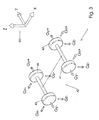
- Fig. 3 shows schematically a vehicle 40 with wheels 41-44 shown in the XY plane of a cartesian coordinate system 50, wherein the direction of forward movement, represented by arrow V, is in X direction. Indicated are the apparent forces (G-forces) which can be exerted with a change of speed at the position of the four wheels 41-44.
- G-forces apparent forces
- the forward apparent force G X+ is for instance most strongly manifest at front wheels 41, 42 of the vehicle in the form of pitching in forward direction, and when a bend to the right is negotiated the apparent force G Y+ to the left manifests itself most strongly at the left-hand wheels 42, 44 in the form of rolling of the vehicle.
- a shock absorber can be assembled for each of the four wheels which provides a firm suspension behaviour specifically for each of these wheels.
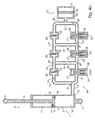
- Fig. 4a shows a diagram for a control device 60 for a shock absorber for the right front wheel 41 of vehicle 40 of fig. 3 , with closing valves 17, 17' and 17" for controlling the liquid flow subject to the occurrence of G-forces G X+ , G Y- and G Z- in respectively forward direction, a direction laterally to the right and vertically downward direction.
- Closing valves 17, 17' and 17" are placed in a first branch 15, 15', 15" of liquid conduit 14, wherein valves 18, 18', 18" are placed in a parallel second branch 16, 16', 16".
- Closing valves 17, 17' and 17" and valves 18, 18', 18" are connected in each case on their respective inlet sides and outlet sides by a conduit part 15/16, 51, 51', 51".
- the axial directions of housings 24, 24' 24" of the respective second valves 17, 17' and 17" in control device 60 are parallel to the direction of the relevant respective G-forces G X+ , G Y- and G Z- .
- the figure shows the control 60 in a first situation, wherein vehicle 40 moves forward at uniform speed, i.e. in the absence of G-forces.
- Fig. 4b shows the diagram for the control device 60 as shown in fig. 4a in a second situation, wherein vehicle 40 brakes sharply, wherein an apparent force G X+ occurs, due to the action of which the closing valve 17 in housing 24 is displaced and the first conduit part 15 is closed.
- a force F represented by arrow F
- a part of the oil flows out of the lower operating space 12 via passage opening 13 into conduit 14 and, as indicated by arrows 29 and 31, flows via the second conduit part 16, the second valve 18 confined under spring pressure, the second conduit part 16', the connecting conduit 51, the first conduit parts 15', 15" and connecting conduit 51" into liquid space 23 of liquid reservoir 19.
- Fig. 4c shows the diagram for the control device 60 as shown in fig. 4a in a third situation, wherein vehicle 40 takes a bend to the left, wherein an apparent force G Y- occurs, due to the action of which the closing valve 17' in housing 24' is displaced and the first conduit part 15' is closed.
- Fig. 4d shows the diagram for the control device 60 as shown in fig. 4a in a fourth situation, wherein vehicle 40 drives over an irregularity in the road surface, for instance a speed bump, wherein an apparent force G Z- occurs, due to the action of which the closing valve 17" in housing 24" is displaced and the first conduit part 15" is closed.
Landscapes
- Engineering & Computer Science (AREA)
- General Engineering & Computer Science (AREA)
- Mechanical Engineering (AREA)
- Fluid-Damping Devices (AREA)
- Vehicle Body Suspensions (AREA)
Claims (7)
- Vorrichtung (20, 60) zum Einlassen von Flüssigkeit in einen Flüssigkeitsbehälter (19) für einen hydraulischen Stoßdämpfer (1) für ein Fahrzeug, welche Vorrichtung mit Regelmitteln (17, 17', 17"; 18, 18', 18") zum Einlassen von Flüssigkeit in den Flüssigkeitsbehälter (19) ausgestattet ist in Abhängigkeit von auf das Fahrzeug einwirkenden G-Kräften, welche Regelmittel (17, 17', 17"; 18, 18', 18") wenigstens ein erstes Ventil (17, 17', 17") und wenigstens ein zweites Ventil (18, 18', 18") enthalten, die in jeweils einem ersten Leitungsteil (15, 15', 15") und einem zweiten dazu parallel angeordneten Leitungsteil (16, 16', 16") einer in den Flüssigkeitsbehälter (19) mündenden Flüssigkeitsleitung (14) bereitgestellt sind, wobei das erste Ventil (17, 17', 17") in geöffnetem Zustand aufgenommen ist und unter Einwirkung einer in eine bestimmte Richtung wirksame G-Kraft abschließbar ist und das zweite Ventil (18, 18', 18") in geschlossenem Zustand gegen einen Vordruck aufgenommen ist, und wobei jeweils ein erstes Ventil (17, 17', 17") und ein zweites Ventil (18, 18', 18") an ihren jeweiligen Einlassseiten und Auslassseiten durch ein Leitungsteil (51, 51', 51") verbunden sind, welches erste Ventil (17, 17', 17") unter Vordruck in die Richtung der wirksamen G-Kraft und quer zum ersten Leitungsteil (15) zwischen einem ersten Stand und einem zweiten Stand verschiebbar ist, dadurch gekennzeichnet, dass das erste Ventil (17, 17', 17") durch einen in einem zylindrischen Gehäuse (24, 24', 24") gegen eine Druckfeder (28) aufgenommenen wenigstens zweiteiligen zylinderförmigen Körper (17, 17', 17") gebildet wird, wovon ein erster Teil (25) einen ersten Durchmesser aufweist, der mit dem Durchmesser des Gehäuses (24, 24', 24") übereinstimmt, und wovon ein zweiter Teil (26) einen zweiten Durchmesser kleiner als den ersten Durchmesser aufweist, in einer solchen Weise, dass das erste Leitungsteil (15, 15', 15") in Abwesenheit der G-Kraft geöffnet ist und das erste Ventil (17, 17', 17") in dem ersten Leitungsteil (15, 15', 15") gegen die durch die Druckfeder (28) gelieferte Federkraft durch eine G-Kraft geschlossen ist, die eine Komponente in der axialen Richtung des Gehäuses (24, 24', 24") aufweist.
- Vorrichtung (20, 60) nach Anspruch 1, dadurch gekennzeichnet, dass der zylindrische Körper mit einer axialen Bohrung (32) für das Verdrängen lassen von Flüssigkeit in das zylindrische Gehäuse (24) bei Verschiebung des Körpers ausgestattet ist.
- Vorrichtung (20, 60) nach einem der Ansprüche 1-2, dadurch gekennzeichnet, dass in dem ersten Leitungsteil (15, 15', 15") mehrere erste Ventile (17, 17', 17") in Serie vorliegen, wobei jedes der Ventile (17, 17', 17") unter Einwirkung einer unterschiedlich gerichteten G-Kraft abschließbar ist.
- Vorrichtung (20, 60) nach einem der Ansprüche 1-3, dadurch gekennzeichnet, dass das zweite Ventil (18) unter einem durch eine Druckfeder gelieferten Vordruck eingeschlossen ist.
- Vorrichtung (20, 60) nach einem der vorigen Ansprüche, wobei der Flüssigkeitsbehälter (19) eine zylindrische Halterung mit einer ersten Kammer (21) zum Halten einer Menge unter einem bestimmten Druck eingeschlossenen Gases und einer durch einen beweglichen Trennkolben (22) davon getrennten zweiten Kammer (23) zur Aufnahme von Flüssigkeit enthält.
- Hydraulischer Stoßdämpfer (1), ausgestattet mit einer Vorrichtung (20, 60) nach einem der Ansprüche 1-5.
- Hydraulischer Stoßdämpfer nach Anspruch 6, dadurch gekennzeichnet, dass die Vorrichtung (20, 60) in einem mit dem Stoßdämpfer (1) integrierten Gehäuse aufgenommen ist.
Applications Claiming Priority (2)
| Application Number | Priority Date | Filing Date | Title |
|---|---|---|---|
| NL1027207A NL1027207C2 (nl) | 2004-10-08 | 2004-10-08 | Inrichting voor het inlaten van vloeistof in een vloeistofreservoir voor een hydraulische schokdemper en hydraulische schokdemper voorzien van een dergelijke inrichting. |
| PCT/NL2005/000704 WO2006038792A1 (en) | 2004-10-08 | 2005-09-29 | Device for letting in liquid into a liquid reservoir for a hydraulic shock absorber and hydraulic shock absorber provided with such a device |
Publications (2)
| Publication Number | Publication Date |
|---|---|
| EP1817185A1 EP1817185A1 (de) | 2007-08-15 |
| EP1817185B1 true EP1817185B1 (de) | 2008-11-12 |
Family
ID=34974169
Family Applications (1)
| Application Number | Title | Priority Date | Filing Date |
|---|---|---|---|
| EP05787475A Expired - Lifetime EP1817185B1 (de) | 2004-10-08 | 2005-09-29 | Vorrichtung zum einlassen einer flüssigkeit in ein flüssigkeitsreservoir für einen hydraulischen stossdämpfer und mit solch einer vorrichtung ausgestatteter hydraulischer stossdämpfer |
Country Status (6)
| Country | Link |
|---|---|
| EP (1) | EP1817185B1 (de) |
| AT (1) | ATE413978T1 (de) |
| DE (1) | DE602005011044D1 (de) |
| ES (1) | ES2317300T3 (de) |
| NL (1) | NL1027207C2 (de) |
| WO (1) | WO2006038792A1 (de) |
Families Citing this family (3)
| Publication number | Priority date | Publication date | Assignee | Title |
|---|---|---|---|---|
| US7273137B2 (en) | 2001-08-30 | 2007-09-25 | Fox Factory, Inc. | Inertia valve shock absorber |
| US7128192B2 (en) | 2001-08-30 | 2006-10-31 | Fox Factory, Inc. | Inertia valve shock absorber |
| US7699146B1 (en) | 2006-04-02 | 2010-04-20 | Fox Factory, Inc. | Suspension damper having inertia valve and user adjustable pressure-relief |
Family Cites Families (13)
| Publication number | Priority date | Publication date | Assignee | Title |
|---|---|---|---|---|
| GB403284A (en) * | 1933-05-03 | 1933-12-21 | Delco Prod Corp | Improvements in or relating to shock absorbers |
| JPS5119888B2 (de) * | 1972-03-27 | 1976-06-21 | ||
| FR2252508A1 (en) * | 1973-11-26 | 1975-06-20 | Gele Pierre | Variable stiffness vehicle suspension damper unit - compressed gas spring volume varies with horiz. acceleration |
| JPS54142725A (en) * | 1978-04-24 | 1979-11-07 | Kayaba Ind Co Ltd | Vehicle height regulator |
| US4210344A (en) * | 1979-01-26 | 1980-07-01 | Charles Curnutt | Controlled shock absorber |
| JPS57101144A (en) * | 1980-12-15 | 1982-06-23 | Kayaba Ind Co Ltd | Hydraulic shock absorber |
| JPS60193708A (ja) * | 1984-03-15 | 1985-10-02 | Mazda Motor Corp | ハイドロニユ−マチツクサスペンシヨン |
| JPS61206836A (ja) * | 1985-03-09 | 1986-09-13 | Suzuki Motor Co Ltd | 可変シヨツクアブソ−バ |
| DE3610937A1 (de) * | 1986-04-02 | 1987-10-08 | Bosch Gmbh Robert | Vorrichtung zur daempfung von bewegungsablaeufen |
| JPS6313805A (ja) * | 1986-07-04 | 1988-01-21 | Toyota Motor Corp | 車輌用ロ−リング及びピツチング制御装置 |
| JPH02246815A (ja) * | 1989-03-20 | 1990-10-02 | Tokico Ltd | サスペンション制御装置 |
| JPH08268027A (ja) * | 1995-03-31 | 1996-10-15 | Kayaba Ind Co Ltd | スタビライザの剛性制御構造 |
| US6267400B1 (en) * | 1999-04-06 | 2001-07-31 | Specialized Bicycle Components, Inc. | Bicycle damping enhancement system |
-
2004
- 2004-10-08 NL NL1027207A patent/NL1027207C2/nl not_active IP Right Cessation
-
2005
- 2005-09-29 AT AT05787475T patent/ATE413978T1/de active
- 2005-09-29 WO PCT/NL2005/000704 patent/WO2006038792A1/en not_active Ceased
- 2005-09-29 DE DE602005011044T patent/DE602005011044D1/de not_active Expired - Lifetime
- 2005-09-29 EP EP05787475A patent/EP1817185B1/de not_active Expired - Lifetime
- 2005-09-29 ES ES05787475T patent/ES2317300T3/es active Active
Also Published As
| Publication number | Publication date |
|---|---|
| DE602005011044D1 (de) | 2008-12-24 |
| WO2006038792A1 (en) | 2006-04-13 |
| ES2317300T3 (es) | 2009-04-16 |
| ATE413978T1 (de) | 2008-11-15 |
| NL1027207C2 (nl) | 2006-04-11 |
| EP1817185A1 (de) | 2007-08-15 |
Similar Documents
| Publication | Publication Date | Title |
|---|---|---|
| US12246572B1 (en) | Load dependent damper for a vehicle suspension system | |
| US11408482B2 (en) | Bypass for a suspension damper | |
| US8210330B2 (en) | Electronically controlled frequency dependent damping | |
| Bauer et al. | Hydropneumatic suspension systems | |
| CN114555975B (zh) | 具有多于一个级的主动阀系统 | |
| JP5579790B2 (ja) | 連続的に調整可能な半能動弁を有する衝撃緩衝器 | |
| US6102418A (en) | Hydropneumatic suspension system | |
| KR101441519B1 (ko) | 정션 블리드 | |
| US6290035B1 (en) | Acceleration sensitive damping for automotive dampers | |
| KR102367578B1 (ko) | 압축 여과 기능을 가진 유압 충격 흡수기 | |
| US6332622B1 (en) | Suspension apparatus having two interconnected shock absorbers | |
| CN102822559A (zh) | 悬架装置 | |
| US20090078517A1 (en) | Damping force adjusting structure of hydraulic shock absorber | |
| DE112005000343B4 (de) | Luftdruckproportionaler Dämpfer für Stossdämpfer | |
| DE102013110219A1 (de) | Fahrzeughöhensteuer/Regel-Einrichtung für ein Motorrad | |
| EP2291588A1 (de) | Hydropneumatische aufhängungseinheit | |
| WO2018015069A1 (de) | Feder- und dämpfungsanordnung für ein motorrad | |
| JP3675853B2 (ja) | 衝撃緩衝装置 | |
| US6615960B1 (en) | Fluid damped shock absorber and method | |
| EP2402626B1 (de) | Umleitung für einen Aufhängungsdämpfer | |
| WO2006038792A1 (en) | Device for letting in liquid into a liquid reservoir for a hydraulic shock absorber and hydraulic shock absorber provided with such a device | |
| EP1666347B1 (de) | Fahrzeugaufhängungsvorrichtung | |
| JP2015158255A (ja) | 流体圧緩衝器 | |
| Senar | Double Hydraulic Stop (DHS) Suspension | |
| GB2378231A (en) | A damper for a vehicle suspension with externally mounted semi-active system |
Legal Events
| Date | Code | Title | Description |
|---|---|---|---|
| PUAI | Public reference made under article 153(3) epc to a published international application that has entered the european phase |
Free format text: ORIGINAL CODE: 0009012 |
|
| 17P | Request for examination filed |
Effective date: 20070207 |
|
| AK | Designated contracting states |
Kind code of ref document: A1 Designated state(s): AT BE BG CH CY CZ DE DK EE ES FI FR GB GR HU IE IS IT LI LT LU LV MC NL PL PT RO SE SI SK TR |
|
| 17Q | First examination report despatched |
Effective date: 20071031 |
|
| DAX | Request for extension of the european patent (deleted) | ||
| GRAP | Despatch of communication of intention to grant a patent |
Free format text: ORIGINAL CODE: EPIDOSNIGR1 |
|
| GRAS | Grant fee paid |
Free format text: ORIGINAL CODE: EPIDOSNIGR3 |
|
| GRAA | (expected) grant |
Free format text: ORIGINAL CODE: 0009210 |
|
| AK | Designated contracting states |
Kind code of ref document: B1 Designated state(s): AT BE BG CH CY CZ DE DK EE ES FI FR GB GR HU IE IS IT LI LT LU LV MC NL PL PT RO SE SI SK TR |
|
| REG | Reference to a national code |
Ref country code: GB Ref legal event code: FG4D |
|
| REG | Reference to a national code |
Ref country code: CH Ref legal event code: EP |
|
| REG | Reference to a national code |
Ref country code: IE Ref legal event code: FG4D |
|
| REF | Corresponds to: |
Ref document number: 602005011044 Country of ref document: DE Date of ref document: 20081224 Kind code of ref document: P |
|
| REG | Reference to a national code |
Ref country code: SE Ref legal event code: TRGR |
|
| REG | Reference to a national code |
Ref country code: ES Ref legal event code: FG2A Ref document number: 2317300 Country of ref document: ES Kind code of ref document: T3 |
|
| LTIE | Lt: invalidation of european patent or patent extension |
Effective date: 20081112 |
|
| PG25 | Lapsed in a contracting state [announced via postgrant information from national office to epo] |
Ref country code: LT Free format text: LAPSE BECAUSE OF FAILURE TO SUBMIT A TRANSLATION OF THE DESCRIPTION OR TO PAY THE FEE WITHIN THE PRESCRIBED TIME-LIMIT Effective date: 20081112 |
|
| PG25 | Lapsed in a contracting state [announced via postgrant information from national office to epo] |
Ref country code: PL Free format text: LAPSE BECAUSE OF FAILURE TO SUBMIT A TRANSLATION OF THE DESCRIPTION OR TO PAY THE FEE WITHIN THE PRESCRIBED TIME-LIMIT Effective date: 20081112 Ref country code: IS Free format text: LAPSE BECAUSE OF FAILURE TO SUBMIT A TRANSLATION OF THE DESCRIPTION OR TO PAY THE FEE WITHIN THE PRESCRIBED TIME-LIMIT Effective date: 20090312 Ref country code: FI Free format text: LAPSE BECAUSE OF FAILURE TO SUBMIT A TRANSLATION OF THE DESCRIPTION OR TO PAY THE FEE WITHIN THE PRESCRIBED TIME-LIMIT Effective date: 20081112 Ref country code: SI Free format text: LAPSE BECAUSE OF FAILURE TO SUBMIT A TRANSLATION OF THE DESCRIPTION OR TO PAY THE FEE WITHIN THE PRESCRIBED TIME-LIMIT Effective date: 20081112 Ref country code: LV Free format text: LAPSE BECAUSE OF FAILURE TO SUBMIT A TRANSLATION OF THE DESCRIPTION OR TO PAY THE FEE WITHIN THE PRESCRIBED TIME-LIMIT Effective date: 20081112 |
|
| PG25 | Lapsed in a contracting state [announced via postgrant information from national office to epo] |
Ref country code: EE Free format text: LAPSE BECAUSE OF FAILURE TO SUBMIT A TRANSLATION OF THE DESCRIPTION OR TO PAY THE FEE WITHIN THE PRESCRIBED TIME-LIMIT Effective date: 20081112 Ref country code: RO Free format text: LAPSE BECAUSE OF FAILURE TO SUBMIT A TRANSLATION OF THE DESCRIPTION OR TO PAY THE FEE WITHIN THE PRESCRIBED TIME-LIMIT Effective date: 20081112 Ref country code: BG Free format text: LAPSE BECAUSE OF FAILURE TO SUBMIT A TRANSLATION OF THE DESCRIPTION OR TO PAY THE FEE WITHIN THE PRESCRIBED TIME-LIMIT Effective date: 20090212 Ref country code: DK Free format text: LAPSE BECAUSE OF FAILURE TO SUBMIT A TRANSLATION OF THE DESCRIPTION OR TO PAY THE FEE WITHIN THE PRESCRIBED TIME-LIMIT Effective date: 20081112 Ref country code: BE Free format text: LAPSE BECAUSE OF FAILURE TO SUBMIT A TRANSLATION OF THE DESCRIPTION OR TO PAY THE FEE WITHIN THE PRESCRIBED TIME-LIMIT Effective date: 20081112 |
|
| PG25 | Lapsed in a contracting state [announced via postgrant information from national office to epo] |
Ref country code: PT Free format text: LAPSE BECAUSE OF FAILURE TO SUBMIT A TRANSLATION OF THE DESCRIPTION OR TO PAY THE FEE WITHIN THE PRESCRIBED TIME-LIMIT Effective date: 20090413 |
|
| PLBE | No opposition filed within time limit |
Free format text: ORIGINAL CODE: 0009261 |
|
| STAA | Information on the status of an ep patent application or granted ep patent |
Free format text: STATUS: NO OPPOSITION FILED WITHIN TIME LIMIT |
|
| PG25 | Lapsed in a contracting state [announced via postgrant information from national office to epo] |
Ref country code: SK Free format text: LAPSE BECAUSE OF FAILURE TO SUBMIT A TRANSLATION OF THE DESCRIPTION OR TO PAY THE FEE WITHIN THE PRESCRIBED TIME-LIMIT Effective date: 20081112 |
|
| 26N | No opposition filed |
Effective date: 20090813 |
|
| PG25 | Lapsed in a contracting state [announced via postgrant information from national office to epo] |
Ref country code: MC Free format text: LAPSE BECAUSE OF NON-PAYMENT OF DUE FEES Effective date: 20090930 |
|
| REG | Reference to a national code |
Ref country code: CH Ref legal event code: PL |
|
| REG | Reference to a national code |
Ref country code: IE Ref legal event code: MM4A |
|
| PG25 | Lapsed in a contracting state [announced via postgrant information from national office to epo] |
Ref country code: IE Free format text: LAPSE BECAUSE OF NON-PAYMENT OF DUE FEES Effective date: 20090929 |
|
| PG25 | Lapsed in a contracting state [announced via postgrant information from national office to epo] |
Ref country code: CH Free format text: LAPSE BECAUSE OF NON-PAYMENT OF DUE FEES Effective date: 20090930 Ref country code: GR Free format text: LAPSE BECAUSE OF FAILURE TO SUBMIT A TRANSLATION OF THE DESCRIPTION OR TO PAY THE FEE WITHIN THE PRESCRIBED TIME-LIMIT Effective date: 20090213 Ref country code: LI Free format text: LAPSE BECAUSE OF NON-PAYMENT OF DUE FEES Effective date: 20090930 |
|
| PG25 | Lapsed in a contracting state [announced via postgrant information from national office to epo] |
Ref country code: LU Free format text: LAPSE BECAUSE OF NON-PAYMENT OF DUE FEES Effective date: 20090929 |
|
| PG25 | Lapsed in a contracting state [announced via postgrant information from national office to epo] |
Ref country code: HU Free format text: LAPSE BECAUSE OF FAILURE TO SUBMIT A TRANSLATION OF THE DESCRIPTION OR TO PAY THE FEE WITHIN THE PRESCRIBED TIME-LIMIT Effective date: 20090513 |
|
| PG25 | Lapsed in a contracting state [announced via postgrant information from national office to epo] |
Ref country code: TR Free format text: LAPSE BECAUSE OF FAILURE TO SUBMIT A TRANSLATION OF THE DESCRIPTION OR TO PAY THE FEE WITHIN THE PRESCRIBED TIME-LIMIT Effective date: 20081112 |
|
| PG25 | Lapsed in a contracting state [announced via postgrant information from national office to epo] |
Ref country code: CY Free format text: LAPSE BECAUSE OF FAILURE TO SUBMIT A TRANSLATION OF THE DESCRIPTION OR TO PAY THE FEE WITHIN THE PRESCRIBED TIME-LIMIT Effective date: 20081112 |
|
| REG | Reference to a national code |
Ref country code: FR Ref legal event code: PLFP Year of fee payment: 12 |
|
| REG | Reference to a national code |
Ref country code: FR Ref legal event code: PLFP Year of fee payment: 13 |
|
| REG | Reference to a national code |
Ref country code: FR Ref legal event code: PLFP Year of fee payment: 14 |
|
| REG | Reference to a national code |
Ref country code: DE Ref legal event code: R082 Ref document number: 602005011044 Country of ref document: DE Representative=s name: SCHOPPE, ZIMMERMANN, STOECKELER, ZINKLER, SCHE, DE Ref country code: DE Ref legal event code: R081 Ref document number: 602005011044 Country of ref document: DE Owner name: RRS HOLDING B.V., NL Free format text: FORMER OWNER: GEBEMA BEHEER B.V., HENGELO, NL |
|
| REG | Reference to a national code |
Ref country code: ES Ref legal event code: PC2A Owner name: RRS HOLDING B.V. Effective date: 20210614 |
|
| REG | Reference to a national code |
Ref country code: GB Ref legal event code: 732E Free format text: REGISTERED BETWEEN 20210603 AND 20210609 |
|
| REG | Reference to a national code |
Ref country code: AT Ref legal event code: PC Ref document number: 413978 Country of ref document: AT Kind code of ref document: T Owner name: RRS HOLDING B.V., NL Effective date: 20210802 |
|
| REG | Reference to a national code |
Ref country code: NL Ref legal event code: PD Owner name: RRS HOLDING B.V.; NL Free format text: DETAILS ASSIGNMENT: CHANGE OF OWNER(S), ASSIGNMENT; FORMER OWNER NAME: GEBEMA BEHEER B.V. Effective date: 20230407 |
|
| PGFP | Annual fee paid to national office [announced via postgrant information from national office to epo] |
Ref country code: DE Payment date: 20240813 Year of fee payment: 20 |
|
| PGFP | Annual fee paid to national office [announced via postgrant information from national office to epo] |
Ref country code: GB Payment date: 20240709 Year of fee payment: 20 |
|
| PGFP | Annual fee paid to national office [announced via postgrant information from national office to epo] |
Ref country code: FR Payment date: 20240709 Year of fee payment: 20 |
|
| PGFP | Annual fee paid to national office [announced via postgrant information from national office to epo] |
Ref country code: NL Payment date: 20240905 Year of fee payment: 20 |
|
| PGFP | Annual fee paid to national office [announced via postgrant information from national office to epo] |
Ref country code: CZ Payment date: 20240807 Year of fee payment: 20 |
|
| PGFP | Annual fee paid to national office [announced via postgrant information from national office to epo] |
Ref country code: AT Payment date: 20240910 Year of fee payment: 20 |
|
| PGFP | Annual fee paid to national office [announced via postgrant information from national office to epo] |
Ref country code: IT Payment date: 20240904 Year of fee payment: 20 Ref country code: SE Payment date: 20240812 Year of fee payment: 20 |
|
| PGFP | Annual fee paid to national office [announced via postgrant information from national office to epo] |
Ref country code: ES Payment date: 20241001 Year of fee payment: 20 |
|
| REG | Reference to a national code |
Ref country code: DE Ref legal event code: R071 Ref document number: 602005011044 Country of ref document: DE |
|
| REG | Reference to a national code |
Ref country code: NL Ref legal event code: MK Effective date: 20250928 |
|
| REG | Reference to a national code |
Ref country code: ES Ref legal event code: FD2A Effective date: 20251006 |
|
| PG25 | Lapsed in a contracting state [announced via postgrant information from national office to epo] |
Ref country code: ES Free format text: LAPSE BECAUSE OF EXPIRATION OF PROTECTION Effective date: 20250930 |
|
| PG25 | Lapsed in a contracting state [announced via postgrant information from national office to epo] |
Ref country code: CZ Free format text: LAPSE BECAUSE OF EXPIRATION OF PROTECTION Effective date: 20250929 |
|
| REG | Reference to a national code |
Ref country code: GB Ref legal event code: PE20 Expiry date: 20250928 |
|
| REG | Reference to a national code |
Ref country code: SE Ref legal event code: EUG |
|
| REG | Reference to a national code |
Ref country code: AT Ref legal event code: MK07 Ref document number: 413978 Country of ref document: AT Kind code of ref document: T Effective date: 20250929 |