EP1817260B1 - Appareil de production d'eau potable a circulation - Google Patents
Appareil de production d'eau potable a circulation Download PDFInfo
- Publication number
- EP1817260B1 EP1817260B1 EP05808426A EP05808426A EP1817260B1 EP 1817260 B1 EP1817260 B1 EP 1817260B1 EP 05808426 A EP05808426 A EP 05808426A EP 05808426 A EP05808426 A EP 05808426A EP 1817260 B1 EP1817260 B1 EP 1817260B1
- Authority
- EP
- European Patent Office
- Prior art keywords
- water
- drinking
- tank
- electronic valve
- collecting tank
- Prior art date
- Legal status (The legal status is an assumption and is not a legal conclusion. Google has not performed a legal analysis and makes no representation as to the accuracy of the status listed.)
- Expired - Lifetime
Links
Images


Classifications
-
- C—CHEMISTRY; METALLURGY
- C02—TREATMENT OF WATER, WASTE WATER, SEWAGE, OR SLUDGE
- C02F—TREATMENT OF WATER, WASTE WATER, SEWAGE, OR SLUDGE
- C02F1/00—Treatment of water, waste water, or sewage
- C02F1/008—Control or steering systems not provided for elsewhere in subclass C02F
-
- B—PERFORMING OPERATIONS; TRANSPORTING
- B01—PHYSICAL OR CHEMICAL PROCESSES OR APPARATUS IN GENERAL
- B01D—SEPARATION
- B01D5/00—Condensation of vapours; Recovering volatile solvents by condensation
- B01D5/0003—Condensation of vapours; Recovering volatile solvents by condensation by using heat-exchange surfaces for indirect contact between gases or vapours and the cooling medium
-
- B—PERFORMING OPERATIONS; TRANSPORTING
- B01—PHYSICAL OR CHEMICAL PROCESSES OR APPARATUS IN GENERAL
- B01D—SEPARATION
- B01D5/00—Condensation of vapours; Recovering volatile solvents by condensation
- B01D5/0033—Other features
- B01D5/0039—Recuperation of heat, e.g. use of heat pump(s), compression
-
- B—PERFORMING OPERATIONS; TRANSPORTING
- B01—PHYSICAL OR CHEMICAL PROCESSES OR APPARATUS IN GENERAL
- B01D—SEPARATION
- B01D5/00—Condensation of vapours; Recovering volatile solvents by condensation
- B01D5/0078—Condensation of vapours; Recovering volatile solvents by condensation characterised by auxiliary systems or arrangements
- B01D5/009—Collecting, removing and/or treatment of the condensate
-
- C—CHEMISTRY; METALLURGY
- C02—TREATMENT OF WATER, WASTE WATER, SEWAGE, OR SLUDGE
- C02F—TREATMENT OF WATER, WASTE WATER, SEWAGE, OR SLUDGE
- C02F1/00—Treatment of water, waste water, or sewage
- C02F1/02—Treatment of water, waste water, or sewage by heating
-
- C—CHEMISTRY; METALLURGY
- C02—TREATMENT OF WATER, WASTE WATER, SEWAGE, OR SLUDGE
- C02F—TREATMENT OF WATER, WASTE WATER, SEWAGE, OR SLUDGE
- C02F1/00—Treatment of water, waste water, or sewage
- C02F1/30—Treatment of water, waste water, or sewage by irradiation
- C02F1/32—Treatment of water, waste water, or sewage by irradiation with ultraviolet light
-
- C—CHEMISTRY; METALLURGY
- C02—TREATMENT OF WATER, WASTE WATER, SEWAGE, OR SLUDGE
- C02F—TREATMENT OF WATER, WASTE WATER, SEWAGE, OR SLUDGE
- C02F1/00—Treatment of water, waste water, or sewage
- C02F1/001—Processes for the treatment of water whereby the filtration technique is of importance
-
- C—CHEMISTRY; METALLURGY
- C02—TREATMENT OF WATER, WASTE WATER, SEWAGE, OR SLUDGE
- C02F—TREATMENT OF WATER, WASTE WATER, SEWAGE, OR SLUDGE
- C02F2201/00—Apparatus for treatment of water, waste water or sewage
- C02F2201/002—Construction details of the apparatus
-
- C—CHEMISTRY; METALLURGY
- C02—TREATMENT OF WATER, WASTE WATER, SEWAGE, OR SLUDGE
- C02F—TREATMENT OF WATER, WASTE WATER, SEWAGE, OR SLUDGE
- C02F2209/00—Controlling or monitoring parameters in water treatment
- C02F2209/40—Liquid flow rate
-
- Y—GENERAL TAGGING OF NEW TECHNOLOGICAL DEVELOPMENTS; GENERAL TAGGING OF CROSS-SECTIONAL TECHNOLOGIES SPANNING OVER SEVERAL SECTIONS OF THE IPC; TECHNICAL SUBJECTS COVERED BY FORMER USPC CROSS-REFERENCE ART COLLECTIONS [XRACs] AND DIGESTS
- Y02—TECHNOLOGIES OR APPLICATIONS FOR MITIGATION OR ADAPTATION AGAINST CLIMATE CHANGE
- Y02A—TECHNOLOGIES FOR ADAPTATION TO CLIMATE CHANGE
- Y02A20/00—Water conservation; Efficient water supply; Efficient water use
Definitions
- the present invention relates to an apparatus for generating drinking water, and more particularly, to a circulation-type apparatus for generating drinking water using moisture in the atmosphere, comprising a continuous circulation/repeat sterilization system, in which the generated drinking water is continuously circulated along a desired path so that the drinking water is repeatedly sterilized and purified to prevent multiplication of bacteria in a drinking-water tank, a water collection tank, a cold-water tank, and a hot-water tank, and also prevent a phenomenon of dust flocculation in the drinking-water tank, thereby perfectly securing the safety for sanitary and clean water quality.
- the atmosphere contains a lot of moisture in vapor form, and humidity is a measure of moisture in the air.
- the humidity is indicated by relative humidity which is a ratio of the amount of water vapor in the saturated air at a specific temperature to the maximum amount that the air could hold at that temperature, and it is often expressed as a percentage.
- the moisture in the air contacts an object of relatively low temperature, the moisture is condensed, and, in turn, is converted into water. This is a phenomenon in that if the air contacts the object of relatively low temperature, the temperature of the air is lowered and the air is converted into a saturated state for the moisture, so that the saturated moisture is condensed.
- the dehumidifier includes a compressor for compressing a coolant, a condenser for condensing the compressed coolant, and an evaporator for evaporating and cooling the condensed coolant.
- the dehumidifier includes a compressor for compressing a coolant, a condenser for condensing the compressed coolant, and an evaporator for evaporating and cooling the condensed coolant.
- the air passes through the evaporator, the moisture in the air is condensed by the evaporator.
- the air passes through the condenser, and, in turn, is warmed. Then, the warmed air is again discharged to the atmosphere.
- the condensed water is cooled by the evaporator, the temperature of the evaporator is raised in a moment to drop the condensed water and then collect it.
- TDS total dissolved material
- a water generating apparatus capable of using the water, which is collected by using a function of a conventional humidifier, as drinking water.
- the water generating apparatus generates the drinking water using the moisture in the atmosphere.
- the water generating apparatus is configured by merely combining the construction of a conventional humidifier with the construction of a conventional purifier, so as to purify the water condensed by the humidifier and, in turn, provide the drinking water.
- a conventional water generating apparatus is configured by merely combining the construction of the humidifier including a compressor, a heat exchanger, and a condenser, with a water purifying means including a water tank and a filter, so as to generate the water. It is effective that a temperature difference between the air and the heat exchanger becomes more than 10°C. In particular, in winter when external temperature is below sub-zero temperature, even though the external air directly passes on a surface of the condenser, it is difficult to obtain the condensed water. Therefore, an efficiency of the system is too decreased.
- the moisture is frozen on the evaporator at temperature of below 0°C. This freezing must be defrosted, so that the water streams down and is collected.
- the conventional apparatus has the following drawbacks. Since pipes of the evaporator are arranged in a horizontal direction, and aluminum pins are densely disposed for the pipes, the defrosting process is delayed. Hence, since a heating means, such as a heater or a hot blast heater, should be provided, the construction of the apparatus is complicated, and thus a manufacturing cost is increased. Also, additional energy is consumed to operate the heating means. In addition, the process of streaming and collecting the water is not smoothly performed.
- the drinking water is supplied from the exterior, and the supplied drinking water is purified, thereby continuously supplying the drinking water. Since a surface of the evaporator is coated by Teflon which is not harmful to a human body, the safety of the drinking water is improved, and the collection of water is quickly achieved. Also, pipes are arranged in a vertical direction, and aluminum pins are not disposed for the pipes, thereby naturally defrosting and collecting the water, without applying heat to the pipes.
- the above drinking-water generating apparatus for generating and purifying the drinking water in the air is sanitarily managed by a purifying filter system and a sterilizing system.
- a drinking-water tank for storing the purified and sterilized water is under the condition suitable for multiplication of bacteria.
- the drinking-water becomes a hotbed of secondary multiplication of bacteria.
- an ultraviolet sterilizing lamp serves not to sterilize 100% of bacterial, but about 70% of bacteria, the remaining bacteria continuously multiply to cause pollution of the drinking-water tank.
- an object of the present invention is to solve the problems involved in the prior art, and to provide a circulation-type apparatus for generating drinking water using moisture in the atmosphere, comprising a continuous circulation/repeat sterilization system, in which the generated drinking water is continuously circulated along a desired path so that the drinking water is repeatedly sterilized and purified to prevent multiplication of bacteria in a drinking-water tank, a water collection tank, a cold-water tank, and a hot-water tank, and also prevent a phenomenon of dust flocculation in the drinking-water tank, thereby perfectly securing the safety for sanitary and clean water quality.
- Another object of the present invention is to provide a circulation-type apparatus for generating drinking water, capable of preventing an electronic valve for supplying auxiliary drinking water from being burned out to improve the reliability of the apparatus.
- the present invention provides a circulation-type drinking-water generating apparatus as defined in claim 1.
- Fig. 1 is a perspective view of a drinking-water generating apparatus according to an embodiment of the present invention.
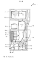
- Fig. 2 is a front cross-sectional view illustrating a drinking-water generating apparatus according to an embodiment of the present invention.
- Fig. 3 is a sectional side elevation illustrating a drinking-water generating apparatus according to an embodiment of the present invention.
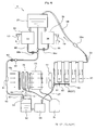
- Fig. 4 is a schematic view illustrating relationship of components of the present invention.
- a circulation-type drinking-water generating apparatus according to an embodiment of the present invention will now be described with reference to the accompanying drawings, the circulation-type drinking-water generating apparatus being represented generally by reference numeral 1.
- the circulation-type drinking-water generating apparatus 1 continuously circulates water to prevent the water from being stagnated in a drinking-water tank, while repeatedly sterilizing and purifying the water, thereby obtaining clean water quality.
- Fig. 1 is a perspective view of a drinking-water generating apparatus according to an embodiment of the present invention
- Fig. 2 is a front cross-sectional view of Fig. 1
- Fig. 3 is a sectional side elevation of FIG. 1
- Fig. 4 is a schematic view illustrating relationship of components of the present invention.
- the circulation-type drinking-water generating apparatus 1 includes a drinking-water freezing system 70 having a fan 77 for supplying air having humidity into a casing 10, an evaporator 75 for condensing the air supplied by the fan 77, a condenser 73 connected to the evaporator 75, and a compressor 71 for compressing a coolant supplied to the evaporator 75 and the condenser 73; a water collecting tank 50 disposed under the evaporator for collecting drinking water condensed on and dropped from a surface of the evaporator; water sterilizing means 60 for sterilizing the drinking water supplied into the water collecting tank 50; a water purifying system 40 for purifying the drinking water collected in the water collecting tank 50; a drinking-water tank 20 for storing the drinking water purified by the water purifying system 40; a water supply pump 65 installed to either of a first water supply pipe 57 passing the water collecting tank 50 with the water purifying system 40 to connect the water
- an ultraviolet sterilizing lamp 91 is installed in the return pipe 90.
- the ultraviolet sterilizing lamp 91 includes an UV lamp, a transparent vessel for housing the UV lamp, and a sterilizing chamber formed on an outside of the transparent vessel and having a narrow passage for guiding the drinking water passing through the return pipe 90. Also, the return pipe 90 is provided with a reduction valve 92 for reducing a flow rate of the drinking water moved down from the drinking-water tank 20. The reduction valve 92 is disposed above the ultraviolet sterilizing lamp for reducing the flow rate of the supplied drinking water, so that a stagnation time of the drinking water in the ultraviolet sterilizing lamp 91 is prolonged to extend a ultraviolet radiating time and thus improve a sterilizing efficiency.
- the water supply pump 65 is operated to discharge the water from the water collecting tank to the water purifying system and the drinking-water tank. If the water supply tank 65 is failed, the water may overflow from the water collecting tank.
- the return pipe 90 is provided with an electronic valve 93 automatically operated when the water collecting tank 50 is filled with the water at a high water level, or a ball-type valve operated by buoyancy when the water collecting tank 50 is filled with the water at a predetermined water level.
- the electronic valve 93 is controlled in such a way that the electronic valve is automatically closed in response to a signal output from the level detection sensor 53.
- a separate level detection sensor (not shown) may be additionally installed.
- the level detection sensor 53 may be configured in a switch type to directly operate the electronic valve when pressure reaches above a predetermined level.
- the return pipe 90 is provided on the upper portion thereof with a flow rate detection sensor 94 for detecting hydraulic pressure of the drinking-water tank 20 to control the electronic valve 93.
- the electronic valve may be connected with the level detection sensor 21 of the drinking-water tank.
- an ultraviolet sterilizing lamp 58a may be additionally installed in the second water supply pipe 58 through which the drinking water is supplied from the water purifying system 40 to the drinking-water tank 20.
- the return pipe 90 is connected to the water sterilizing lamp 60 installed on the upper portion of the water collecting tank 50.
- the return pipe 90 is connected to a cold-water return branch pipe 96 connected to the cold-water tank 38 of the water cooling unit and provided with an electronic valve 96a which is controlled by the micom (see Fig. 4 ).
- the electronic valve 96a of the cold-water return branch pipe 96 is controlled to be opened or closed periodically or in time of low use frequency.
- the electronic valve 96a of the cold-water return branch pipe 96 may be opened, for example, during 10 minutes every 4 hours or during 20 minutes in time of low use frequency, i.e., at about 3 a.m.
- the electronic valve 96a of the cold-water return branch pipe 96 may be opened or closed during a predetermined time when the night time is detected by an illumination detection sensor.
- the water in the cold-water tank 38 is circulated through the return branch pipe 96 and the return pipe 90 periodically or in time of low use frequency. Hence, if the cooled water is not used for a long time, bacteria do not multiply in the cold-water tank.
- the water stored in the hot-water tank 33 is sterilized by the heat generated from the heater during operation of the water heating unit 30.
- the hot water is not used in tropical regions such as the Middle East. If the water heating unit is turned off, the hot-water tank becomes a hotbed of the multiplication of bacteria.
- the return pipe 90 is connected to a hot-water return branch pipe 98 connected to the hot-water tank 33 of the water heating unit and provided with an electronic valve 98a which is controlled by the micom (see Fig. 4 ).
- the electronic valve 96a of the hot-water return branch pipe 98 is controlled to be opened or closed periodically when the water heating unit 30 is turned off.
- an auxiliary drinking-water supply means 80 may be provided, the auxiliary drinking-water supply means including an external water supply pipe 81 communicated with the first water supply pipe 57 between the water collecting tank and the water purifying system, and an electronic valve 83 for opening or closing the external water supply pipe 81.
- the electronic valve 83 is automatically opened by the micom, so that the auxiliary drinking-water supply means can supply the drinking water from the exterior through the external water supply pipe 81. Accordingly, in the case where the generation of the drinking water using the moisture in the air is not properly achieved, the supply of drinking water is not interrupted.
- the external water supply pipe 81 is provided with the electronic valve 83 and means for protecting the electronic valve to control ON/OFF of the electronic valve 83 (see Fig. 4 ).
- the means for protecting the electronic valve has a hydraulic pressure detection sensor 85 of the external water supply pipe 81, and the electronic valve 83 is controlled to intercept the power when the hydraulic pressure detection sensor 85 outputs a lower hydraulic pressure detection signal.
- the means for protecting the electronic valve locks the electronic valve 83 in the case where the drinking water is properly generated.
- levels of the drinking-water tank 20 and the water collecting tank 50 are not raised during a predetermined time, when a level of the drinking-water tank is lowered below a predetermined level, or when a temperature difference between temperature of the external air detected by an external-air temperature sensor and temperature of the evaporator 75 detected by an evaporator temperature sensor becomes below 10°C, the electronic valve 83 is automatically opened by the micom, so that the drinking water is supplied from the exterior through the external water supply pipe 81.
- the hydraulic pressure detection sensor 85 sends the low hydraulic pressure signal to the micom, so that the micom intercepts the power of the electronic valve 83 to stop the operation of the electronic valve.
- the hydraulic pressure in the external water supply tube 81 is returned to a normal level by the hydraulic pressure detection sensor 85, the power is again applied to the electronic valve 83.
- the electronic valve 83 is automatically ON/OFF in accordance with supply or suspension of external water supply, thereby easily maintaining the apparatus and extending a lifetime of the apparatus.
- An additional switch 87 may be installed in the electronic valve 83 as the means for protecting the electronic valve.
- the switch 87 manually interrupts the power of the electronic valve in the case where the external water is not supplied, thereby protecting the electronic valve.
- reference numeral 17 denotes a hot-water supply knob
- 18a denotes an air filter
- 19 denotes a cold-water supply knob
- 33 denotes a hot-water tank
- 36 denotes a compressor for cold water
- 38 denotes a cold-water tank
- 41, 42, 43, and 44 denote a purified-water filter
- 66 denotes a water collecting plate.
- the compressor 71 and the fan 77 of the drinking-water freezing system 70 are operated by the control of the micom, and the evaporator 75 is cooled by operation of the compressor 71. At that time, the moisture in the air supplied into the casing 10 through the filter 18a by the fan 77 is condensed on the surface of the evaporator 75. When the air passes through the evaporator 75, the moisture in the air is taken away, and the temperature of the air is raised. In turn, the air is discharged outwardly through a discharge net 18b.
- the drinking water which is collected by the water collecting plate 66 under the evaporator 75 passes through the ultraviolet sterilizing lamp 60 installed on the upper portion of the water collecting tank 50, the drinking water is sterilized, and, in turn, is stored in the water collecting tank 50.
- the water collecting tank 50 is gradually filled with the drinking water by repeatedly turning the compressor 71 on/off. If the predetermined level of the water collecting tank 50 is detected by the level detection sensor 53, the micom 50 drives the water supply pump 65. If the water supply pump 65 is driven, the drinking water in the water collecting tank 50 passes through the water purifying system 40, and the purified drinking water is supplied into the dinking-water tank 20.
- the drinking water of the drinking-water tank is supplied to the hot-water tank 33 and the cold-water tank 38 through a discharge outlet 23.
- the drinking water contained in the hot-water tank 33 and the cold-water tank 38 is heated and cooled by the heater and the cold-water evaporator, respectively.
- the user may operate the hot-water supply knob 17 and/or the cold-water supply knob 19 to discharge the dinking water.
- the micom stops the operation of the compressor 71 to interrupt the condensation and collection of the water.
- the drinking water is hardly generated, for example, when levels of the drinking-water tank 20 and the water collecting tank 50 are not raised during a predetermined time, when the water in the drinking-water tank 20 is dropped below a predetermined level, or when a temperature difference between temperature of the external air detected by an external-air temperature sensor and temperature of the evaporator 75 detected by an evaporator temperature sensor becomes below 10°C, the drinking-water supply valve 83 is automatically opened by the micom, so that the drinking water may be supplied from the exterior through the external water supply pipe 81. Otherwise, the micom may notify the user of the fact that the drinking water is not automatically generated, so that the user can select a dual selection button.
- the drinking water is dropped toward the water collecting tank 50 from the drinking-water tank 20 through the return pipe 90, and is continuously circulated in the course of the drinking-water tank 20, the return pipe 90, the water collecting tank 50, the water supply tank 65, the first water supply pipe 57, the water purifying system 40, the second water supply pipe 58, and the drinking-water tank 20.
- the water is not stagnated in the drinking-water tank 20, but is continuously circulated.
- the drinking water passes through the ultraviolet sterilizing lamps 91 and 58a installed in the return pipe 90 and the second water supply pipe 58 and the filters 41, 42, 43, and 44 of the water purifying system 40 in the circulating course, so that the drinking water is repeatedly sterilized and purified, thereby obtaining the clean and sanitary water quality.
- the reduction valve 92 is installed in the return pipe 90, the water passes through the ultraviolet sterilizing lamp 91 at very slowly speed, so that the staying time of the drinking water in the sterilizing chamber is prolonged to maximize the sterilizing efficiency.
- the circulation system is repeatedly operated during 24 hours, and the circulating period may be adjusted by the reduction valve 92.
- the electronic valve 93 is installed on the connection between the water collecting tank 50 of the return pipe 90, when the water in the water collecting tank 50 reaches a predetermined level, for example, due to the failure of the water supply pump 65, the return pipe 90 is interrupted to stop the inflow of the water and thereby to secure the safety.
- the electronic valve is closed. After the water is filled to a predetermined standard level, the electronic valve is opened.
- the cold-water tank and the hot-water tank are provided with the return branch pipes 96 and 98, respectively, so as to perform the stagnation preventive circulation, thereby achieving the sanitary management of the drinking water.
- the circulation-type drinking-water generating apparatus includes the continuous circulation/repeat sterilization system, in which the generated drinking water is continuously circulated along a desired path so that the drinking water is repeatedly sterilized and purified to prevent multiplication of bacteria in the drinking-water tank and the water collection tank and also prevent a phenomenon of dust flocculation in the drinking-water tank, thereby obtaining the sanitary drinking water. Also, the present invention prevents the electronic valve for the auxiliary drinking-water supply means from being burned out, thereby improving the reliability of the apparatus.
- the circulation-type apparatus for generating drinking water using moisture in the atmosphere includes a continuous circulation/repeat sterilization system, in which the generated drinking water is continuously circulated along a desired path so that the drinking water is repeatedly sterilized and purified to prevent multiplication of bacteria in a drinking-water tank, a water collection tank, a cold-water tank, and a hot-water tank, and also prevent a phenomenon of dust flocculation in the drinking-water tank, thereby perfectly securing the safety for sanitary and clean water quality.
- the present invention prevents the electronic valve for the auxiliary drinking-water supply means from being burned out, thereby improving the reliability of the apparatus.
Landscapes
- Chemical & Material Sciences (AREA)
- Chemical Kinetics & Catalysis (AREA)
- Life Sciences & Earth Sciences (AREA)
- Hydrology & Water Resources (AREA)
- Engineering & Computer Science (AREA)
- Environmental & Geological Engineering (AREA)
- Water Supply & Treatment (AREA)
- Organic Chemistry (AREA)
- Health & Medical Sciences (AREA)
- Toxicology (AREA)
- Physical Water Treatments (AREA)
- Heat Treatment Of Water, Waste Water Or Sewage (AREA)
Abstract
Claims (14)
- Appareil de production d'eau potable à circulation (1) comprenant : un système de réfrigération d'eau (70) ayant un ventilateur (77) destiné à amener de l'air chargé d'humidité dans un caisson (10), un évaporateur (75) destiné à condenser l'air amené par le ventilateur (77), un condenseur (73) raccordé à l'évaporateur (75), et un compresseur (71) destiné à comprimer un liquide de refroidissement amené à l'évaporateur (75) et au condenseur (73) ; un réservoir de récupération d'eau (50) placé sous l'évaporateur et destiné à récupérer l'eau potable condensée à la surface de l'évaporateur et s'en écoulant ; un moyen de stérilisation d'eau (60) destiné à stériliser l'eau potable amenée dans le réservoir de récupération d'eau (50) ; un système de purification d'eau (40) destiné à purifier l'eau potable récupérée dans le réservoir de récupération d'eau (50) ; un réservoir d'eau potable (20) destiné à stocker l'eau potable purifiée par le système de purification d'eau (40) ; une pompe d'amenée d'eau (65) installée soit sur un premier tuyau d'amenée d'eau (57) passant par le réservoir de récupération d'eau (50) associé au système de purification d'eau (40), pour raccorder le réservoir de récupération d'eau (20) au système de purification d'eau (40), soit sur un second tuyau d'amenée d'eau (58) destiné à raccorder le système de purification d'eau (40) au réservoir d'eau potable (20) ; une unité de chauffage d'eau (30) et une unité de refroidissement d'eau (35) destinées respectivement à chauffer et refroidir l'eau potable arrivant du réservoir d'eau potable (20) ; et un micom destiné à contrôler le fonctionnement des composants,
appareil dans lequel un tuyau de retour (90) est raccordé au réservoir d'eau potable (20) et au réservoir de récupération d'eau (50) afin de renvoyer l'eau potable au réservoir de récupération d'eau (50), en assurant ainsi une circulation continue de celle-ci, dans lequel le tuyau de retour (90) est raccordé à un tuyau de dérivation de retour d'eau froide (96) raccordé au réservoir d'eau froide (38) de l'unité de refroidissement d'eau et muni d'un robinet électronique (96a) commandée par le micom, et dans lequel le tuyau de retour (90) est raccordé à un tuyau de dérivation de retour d'eau chaude (98) raccordé au réservoir d'eau chaude (33) de l'unité de chauffage d'eau et muni d'un robinet électronique (98a) commandé par le micom. - Appareil selon la revendication 1, dans lequel une lampe de stérilisation aux ultraviolets (91) est installée dans le tuyau de retour (90).
- Appareil selon la revendication 2, dans lequel le tuyau de retour (90) est muni d'un robinet détendeur (92) destiné à réduire le débit de l'eau potable descendant du réservoir d'eau potable (20).
- Appareil selon la revendication 1 ou 2, dans lequel le tuyau de retour (90) est muni d'un robinet électronique (93) qui est actionné en cas de niveau élevé du réservoir de récupération d'eau (50) ou de faible niveau du réservoir d'eau potable (20).
- Appareil selon la revendication 1 ou 2, dans lequel le tuyau de retour (90) est muni dans sa partie supérieure d'un débitmètre (94) destiné à détecter la pression hydraulique du réservoir d'eau potable (20) pour commander le robinet électronique (93).
- Appareil selon la revendication 4, dans lequel le robinet électronique (93) est automatiquement fermé en réponse à un signal émis par un capteur de niveau (53) installé dans le réservoir de récupération d'eau (50), ou par un capteur de niveau supplémentaire.
- Appareil selon la revendication 1, dans lequel une lampe de stérilisation aux ultraviolets est en outre installée dans le second tuyau d'amenée d'eau (58), par lequel l'eau potable est amenée du système de purification d'eau (40) au réservoir d'eau potable (20).
- Appareil selon la revendication 1, dans lequel le tuyau de retour (90) est raccordé à la lampe de stérilisation aux ultraviolets (60) installée sur la partie supérieure du réservoir de récupération d'eau (50).
- Appareil selon la revendication 1, dans lequel le robinet électronique (96a) du tuyau de dérivation de retour d'eau froide (96) est commandé de manière à s'ouvrir ou à se fermer périodiquement, ou en cas d'usage peu fréquent.
- Appareil selon la revendication 1, dans lequel le robinet électronique (96a) du tuyau de dérivation de retour d'eau froide (96) s'ouvre ou se ferme pendant une durée prédéfinie, lorsqu'un capteur de luminosité détecte qu'il fait nuit.
- Appareil selon la revendication 1, dans lequel le robinet électronique (96a) du tuyau de dérivation de retour d'eau chaude (98) est commandé de manière à s'ouvrir ou à se fermer périodiquement lorsque l'unité de chauffage d'eau (30) est éteinte.
- Appareil selon la revendication 1, comprenant en outre un moyen auxiliaire d'amenée d'eau potable (80) - ce dernier comprenant un tuyau d'amenée d'eau extérieure (81) communiquant avec le premier tuyau d'amenée d'eau (57) situé entre le réservoir de récupération d'eau et le système de purification d'eau-, un robinet électronique (83) destiné à ouvrir ou fermer le tuyau d'amenée d'eau extérieure (81), ainsi qu'un moyen de protection de la fonction marche/arrêt du robinet électronique (83).
- Appareil selon la revendication 12, dans lequel le moyen de protection du robinet électronique comporte un capteur de pression hydraulique (85) du tuyau d'amenée d'eau extérieure (81), et dans lequel le robinet électronique (83) est commandé de manière à couper une tension d'alimentation électrique lorsque le capteur de pression hydraulique (85) émet un signal de détection d'une faible pression hydraulique.
- Appareil selon la revendication 12, dans lequel un contacteur supplémentaire (87) est installé dans le robinet électronique (83) à titre de moyen de protection de ce dernier.
Applications Claiming Priority (2)
| Application Number | Priority Date | Filing Date | Title |
|---|---|---|---|
| KR1020040090487A KR100594362B1 (ko) | 2004-11-08 | 2004-11-08 | 순환식 식수생성장치 |
| PCT/KR2005/002995 WO2006049387A1 (fr) | 2004-11-08 | 2005-09-12 | Appareil de production d'eau potable a circulation |
Publications (3)
| Publication Number | Publication Date |
|---|---|
| EP1817260A1 EP1817260A1 (fr) | 2007-08-15 |
| EP1817260A4 EP1817260A4 (fr) | 2010-09-29 |
| EP1817260B1 true EP1817260B1 (fr) | 2012-07-25 |
Family
ID=36319368
Family Applications (1)
| Application Number | Title | Priority Date | Filing Date |
|---|---|---|---|
| EP05808426A Expired - Lifetime EP1817260B1 (fr) | 2004-11-08 | 2005-09-12 | Appareil de production d'eau potable a circulation |
Country Status (8)
| Country | Link |
|---|---|
| US (1) | US20080104978A1 (fr) |
| EP (1) | EP1817260B1 (fr) |
| JP (1) | JP4457151B2 (fr) |
| KR (1) | KR100594362B1 (fr) |
| CN (1) | CN101056824A (fr) |
| ES (1) | ES2391730T3 (fr) |
| PT (1) | PT1817260E (fr) |
| WO (1) | WO2006049387A1 (fr) |
Cited By (3)
| Publication number | Priority date | Publication date | Assignee | Title |
|---|---|---|---|---|
| CN104341012A (zh) * | 2013-08-04 | 2015-02-11 | 四川锦美环保科技有限公司 | 一种可以有效控制循环冷却水停留时间的方法和装置 |
| CN105105597A (zh) * | 2013-09-20 | 2015-12-02 | 泉州市汇辰产品设计有限公司 | 一种新型茶盘 |
| CN105105598A (zh) * | 2013-10-22 | 2015-12-02 | 德化县丽德家居用品有限公司 | 一种带过滤槽的茶盘 |
Families Citing this family (69)
| Publication number | Priority date | Publication date | Assignee | Title |
|---|---|---|---|---|
| CA2651828A1 (fr) * | 2006-05-15 | 2007-11-22 | Island Sky Corporation | Appareil et methodes polyvalents de production adiabatique d'eau potable |
| KR20080007804A (ko) * | 2006-07-18 | 2008-01-23 | 볼보 컨스트럭션 이키프먼트 홀딩 스웨덴 에이비 | 건설중장비의 에어콘 응축수 취출장치 |
| KR101322777B1 (ko) * | 2007-02-16 | 2013-10-29 | 삼성전자주식회사 | 냉장고 및 그 제어방법 |
| RU2350565C2 (ru) * | 2007-04-02 | 2009-03-27 | Марат Мусагитович Муратов | Установка очистки воды |
| KR100843313B1 (ko) * | 2007-11-13 | 2008-07-03 | 주식회사 동양일렉트로닉스 | 순환식 정수기 |
| DE202009018489U1 (de) * | 2008-04-02 | 2012-02-29 | Sol-Uv Technologie & Entwicklungs-Gmbh | Anlage zur Aufbereitung von Trinkwasser |
| WO2010056486A2 (fr) * | 2008-11-17 | 2010-05-20 | EcoloBlue, Inc. | Appareil et procédés de fabrication d'eau gazeuse à partir de l'atmosphère |
| US8302412B2 (en) | 2008-11-17 | 2012-11-06 | EcoloBlue, Inc. | Versatile environmentally conscious apparatus |
| US8574490B2 (en) * | 2009-03-31 | 2013-11-05 | Bactriblue, Ltd. | Methods and apparatus for reducing count of infectious agents in intravenous access systems |
| AU2009100863B4 (en) * | 2009-08-27 | 2009-11-05 | Agwill Pty Ltd | Water dispensing unit |
| ES2669843T3 (es) * | 2010-04-30 | 2018-05-29 | Jimmy Wan | Generador de agua dulce que utiliza aire |
| TWI569301B (zh) * | 2010-06-04 | 2017-02-01 | 通路實業集團國際公司 | 感應耦合介電質屏障放電燈 |
| KR101017282B1 (ko) * | 2010-06-08 | 2011-02-28 | 구효홍 | 순환식 에어 워터 생성을 활용한 정수기 |
| JP5002686B2 (ja) * | 2010-06-30 | 2012-08-15 | パナソニック株式会社 | 創水装置 |
| EP2593612A4 (fr) * | 2010-07-16 | 2015-05-06 | Ecoloblue Inc | Appareil écologique polyvalent |
| US8980174B2 (en) | 2011-05-13 | 2015-03-17 | Bactriblue, Ltd. | Methods and apparatus for reducing count of infectious agents in intravenous access system |
| CN102287888B (zh) * | 2011-07-18 | 2013-01-09 | 李玉营 | 空气加湿和吸收空气水份制饮用水的一体机 |
| IL217213A (en) * | 2011-12-26 | 2014-06-30 | Yehuda Forte | Water facility that includes a cleaning mechanism |
| KR101325119B1 (ko) * | 2012-02-03 | 2013-11-06 | 주식회사 이앤이로하텍 | 정수기용 살균 크리닝장치 및 이를 갖는 정수기 |
| EP2829518A4 (fr) | 2012-03-21 | 2015-09-30 | Seoul Viosys Co Ltd | Système de purification d'eau utilisant des del ultraviolettes |
| CN103422538A (zh) * | 2012-05-18 | 2013-12-04 | 湖北江南专用特种汽车有限公司 | 一种多功能应急饮用水制取机 |
| CN102847336A (zh) * | 2012-09-10 | 2013-01-02 | 山东汉方制药有限公司 | 一种药品提取浓缩冷凝水再利用系统 |
| CN103015485B (zh) * | 2012-11-06 | 2014-03-19 | 莱芜天一冷暖科技有限公司 | 空气制水机 |
| CN103158955B (zh) * | 2013-03-25 | 2015-05-06 | 上海市政工程设计研究总院(集团)有限公司 | 一种药剂储液系统及其工作方法 |
| JP6212703B2 (ja) * | 2013-05-16 | 2017-10-18 | 株式会社Mizuha | 浄水装置 |
| JP6247021B2 (ja) * | 2013-05-16 | 2017-12-13 | 株式会社Mizuha | 取水装置 |
| CN104234130A (zh) * | 2013-06-06 | 2014-12-24 | 侯兆伟 | 一种制水机及其智能控制方法 |
| CN104422120B (zh) * | 2013-08-29 | 2017-03-15 | 王锦林 | 节能型净化开水器 |
| JP2016537277A (ja) | 2013-10-08 | 2016-12-01 | スカイウェル, リミテッド ライアビリティー カンパニーSkywell, LLC | 大気水発生システムおよび方法 |
| CN104545443B (zh) * | 2013-10-11 | 2017-01-04 | 德化县丽德家居用品有限公司 | 带双重冷凝的空气供水茶盘 |
| WO2016013886A1 (fr) * | 2014-07-25 | 2016-01-28 | 주식회사 에이치이앤지 | Dispositif d'alimentation en air-eau |
| CN104110759A (zh) * | 2014-08-06 | 2014-10-22 | 沁园集团股份有限公司 | 一种空气净化器 |
| KR101702735B1 (ko) * | 2015-01-08 | 2017-02-03 | 엘지전자 주식회사 | 정수기 |
| CN104986439B (zh) * | 2015-05-22 | 2019-02-22 | 佛山市顺德区美的饮水机制造有限公司 | 净水设备的水袋组件及具有其的净水设备 |
| KR101676959B1 (ko) * | 2015-06-02 | 2016-11-16 | 유수호 | 에어 정수기 |
| CN105064456A (zh) * | 2015-07-28 | 2015-11-18 | 李建芳 | 一种将空气的水分子转变成饮用水的装置 |
| CN105347517A (zh) * | 2015-11-23 | 2016-02-24 | 邹斌 | 一种采用电子磁水技术进行冷凝管除垢的空气制水机 |
| RU2609811C1 (ru) * | 2015-12-14 | 2017-02-06 | Александр Алексеевич Соловьев | Установка для получения пресной воды из атмосферного воздуха |
| CN105862979A (zh) * | 2016-05-12 | 2016-08-17 | 张萍 | 一种高效的智能化空气制水机 |
| CN105839704A (zh) * | 2016-05-14 | 2016-08-10 | 张萍 | 一种高效制水的空气制水机 |
| CN105839703A (zh) * | 2016-05-14 | 2016-08-10 | 张萍 | 一种均衡制水的空气制水机 |
| CN105839705A (zh) * | 2016-05-14 | 2016-08-10 | 张萍 | 一种工作效率高的空气制水机 |
| CN105926715A (zh) * | 2016-06-15 | 2016-09-07 | 张萍 | 一种具有实时监测功能的高效净水的空气制水机 |
| CN105926720A (zh) * | 2016-06-15 | 2016-09-07 | 张萍 | 一种高净水效率的空气制水机 |
| CN105926719A (zh) * | 2016-06-15 | 2016-09-07 | 张萍 | 一种新型净水效率高的空气制水机 |
| CN105926721A (zh) * | 2016-06-15 | 2016-09-07 | 张萍 | 一种水净化效率高的智能空气制水机 |
| CN105926714A (zh) * | 2016-06-15 | 2016-09-07 | 张萍 | 一种高净水效率的新型空气制水机 |
| CN105926716A (zh) * | 2016-06-15 | 2016-09-07 | 张萍 | 一种具有精确检测功能的高效净水的空气制水机 |
| JP6124190B1 (ja) * | 2016-06-30 | 2017-05-10 | 夢想科学株式会社 | 取水装置 |
| CN106044883A (zh) * | 2016-07-11 | 2016-10-26 | 佛山市美的清湖净水设备有限公司 | 饮用水制备装置 |
| CN106088234A (zh) * | 2016-08-03 | 2016-11-09 | 张萍 | 一种具有水质监测功能的空气制水机 |
| JP7033065B2 (ja) * | 2016-08-04 | 2022-03-09 | 有限会社テル | 飲料水の供給装置 |
| CN107761822A (zh) * | 2016-08-22 | 2018-03-06 | 深圳市天泉环保科技有限公司 | 一种制水、制冷、空气净化集成系统 |
| CN106419564A (zh) * | 2016-12-09 | 2017-02-22 | 卿琦 | 一种具有制冷加热过滤功能的安全饮水机 |
| CN107352687B (zh) * | 2017-07-31 | 2023-04-18 | 湖南长翔实业有限公司 | 一种水净化保质系统 |
| FR3070383B1 (fr) * | 2017-08-31 | 2021-08-20 | Solable | Appareil de traitement d'eau |
| CN107842063A (zh) * | 2017-11-30 | 2018-03-27 | 天津中德应用技术大学 | 除湿制水一体机 |
| CN108411979A (zh) * | 2018-04-27 | 2018-08-17 | 安徽工程大学 | 一种收集湿气的饮用水设备 |
| CN109224549A (zh) * | 2018-09-27 | 2019-01-18 | 温志聪 | 一种基于物联网的智能家居用自来水过滤装置 |
| CN110685320A (zh) * | 2019-11-06 | 2020-01-14 | 深圳澳蓝智康爱特科技发展有限公司 | 一种节能环保的空气制水机 |
| JP2022041584A (ja) * | 2020-09-01 | 2022-03-11 | Enell株式会社 | 液体処理装置 |
| CN113479956A (zh) * | 2021-08-21 | 2021-10-08 | 江西渥泰环保科技有限公司 | 一种小区用可防止浪费的直饮水设备 |
| MX2024005090A (es) * | 2021-10-26 | 2024-07-19 | Regeneron Pharma | Sistemas y metodos para generar agua de laboratorio y distribuir agua de laboratorio a diferentes temperaturas. |
| CN113925350B (zh) * | 2021-11-02 | 2024-06-07 | 重庆空气水智能科技研究院 | 空气取水自动出售饮用水装置 |
| JP7188723B1 (ja) | 2022-06-24 | 2022-12-13 | 株式会社デンケン | 製水装置 |
| CN115875844A (zh) * | 2022-11-28 | 2023-03-31 | 青岛海尔施特劳斯水设备有限公司 | 可调出水温度的净水装置 |
| JP7525218B1 (ja) * | 2024-04-11 | 2024-07-30 | アクアムホールディングス株式会社 | 空気製水機 |
| CN119638144A (zh) * | 2024-12-31 | 2025-03-18 | 佛山市顺德区美的饮水机制造有限公司 | 净水器的水路系统 |
| CN119769910A (zh) * | 2025-01-02 | 2025-04-08 | 广东新宝电器股份有限公司 | 一种多功能饮水机 |
Family Cites Families (16)
| Publication number | Priority date | Publication date | Assignee | Title |
|---|---|---|---|---|
| US4969991A (en) * | 1989-08-30 | 1990-11-13 | Valadez Gerardo M | Water purifying and dispensing system |
| US5203989A (en) * | 1991-01-30 | 1993-04-20 | Reidy James J | Portable air-water generator |
| US6182453B1 (en) * | 1996-04-08 | 2001-02-06 | Worldwide Water, Inc. | Portable, potable water recovery and dispensing apparatus |
| US5889684A (en) * | 1996-10-18 | 1999-03-30 | Waterlogic International Ltd. | Computer-controlled heated and/or cooled liquid dispenser |
| EP1056976A4 (fr) * | 1998-02-27 | 2004-06-16 | Water Master Technologies Ltd | Appareil de production d'eau |
| KR20000014834A (ko) * | 1998-08-25 | 2000-03-15 | 임승지 | 물 생성장치 |
| US6237352B1 (en) * | 1999-08-18 | 2001-05-29 | Winton J. Goodchild | Water producing and dispensing machine |
| US6684648B2 (en) * | 2000-07-26 | 2004-02-03 | Fakieh Research & Development Center | Apparatus for the production of freshwater from extremely hot and humid air |
| JP2002153874A (ja) * | 2000-09-06 | 2002-05-28 | Oki Jushi Kogyo Kk | 殺菌水製造方法と殺菌水製造装置 |
| US6931756B2 (en) * | 2001-06-08 | 2005-08-23 | Michael Morgan | Combination dehydrator and condensed water dispenser |
| US7089763B2 (en) * | 2002-02-25 | 2006-08-15 | Worldwide Water, L.L.C. | Portable, potable water recovery and dispensing apparatus |
| US6755037B2 (en) * | 2002-08-30 | 2004-06-29 | Global Water Limited | Apparatus and method for extracting potable water from atmosphere |
| KR200337958Y1 (ko) * | 2003-08-06 | 2004-01-07 | (주)에코에이드 | 살균장치를 구비한 정수기 |
| US7175760B2 (en) * | 2004-07-07 | 2007-02-13 | Innowave, Inc. | Water dispensing apparatus with water recirculation line |
| US7540167B2 (en) * | 2004-07-08 | 2009-06-02 | Dean Murphy | Condensed water production system |
| CA2580623A1 (fr) * | 2004-09-03 | 2006-03-16 | Everest International, Ltd. | Procede et dispositif pour la production d'eau |
-
2004
- 2004-11-08 KR KR1020040090487A patent/KR100594362B1/ko not_active Ceased
-
2005
- 2005-09-12 JP JP2007540244A patent/JP4457151B2/ja not_active Expired - Fee Related
- 2005-09-12 CN CNA2005800382024A patent/CN101056824A/zh active Pending
- 2005-09-12 ES ES05808426T patent/ES2391730T3/es not_active Expired - Lifetime
- 2005-09-12 EP EP05808426A patent/EP1817260B1/fr not_active Expired - Lifetime
- 2005-09-12 US US11/718,883 patent/US20080104978A1/en not_active Abandoned
- 2005-09-12 WO PCT/KR2005/002995 patent/WO2006049387A1/fr not_active Ceased
- 2005-09-12 PT PT05808426T patent/PT1817260E/pt unknown
Cited By (3)
| Publication number | Priority date | Publication date | Assignee | Title |
|---|---|---|---|---|
| CN104341012A (zh) * | 2013-08-04 | 2015-02-11 | 四川锦美环保科技有限公司 | 一种可以有效控制循环冷却水停留时间的方法和装置 |
| CN105105597A (zh) * | 2013-09-20 | 2015-12-02 | 泉州市汇辰产品设计有限公司 | 一种新型茶盘 |
| CN105105598A (zh) * | 2013-10-22 | 2015-12-02 | 德化县丽德家居用品有限公司 | 一种带过滤槽的茶盘 |
Also Published As
| Publication number | Publication date |
|---|---|
| ES2391730T3 (es) | 2012-11-29 |
| JP2008519189A (ja) | 2008-06-05 |
| JP4457151B2 (ja) | 2010-04-28 |
| WO2006049387A1 (fr) | 2006-05-11 |
| KR20060041409A (ko) | 2006-05-12 |
| EP1817260A4 (fr) | 2010-09-29 |
| KR100594362B1 (ko) | 2006-06-30 |
| PT1817260E (pt) | 2012-10-30 |
| US20080104978A1 (en) | 2008-05-08 |
| EP1817260A1 (fr) | 2007-08-15 |
| CN101056824A (zh) | 2007-10-17 |
Similar Documents
| Publication | Publication Date | Title |
|---|---|---|
| US20080104978A1 (en) | Circulation-Type Apparatus for Generating Drinking Water | |
| US6405551B1 (en) | Heating apparatus having refrigeration cycle | |
| KR100843313B1 (ko) | 순환식 정수기 | |
| AU2005282371B2 (en) | Water producing method and apparatus | |
| US5286351A (en) | Water distilling method | |
| CN101542220B (zh) | 多用途隔热的饮用水生产设备和方法 | |
| CN101929179B (zh) | 空气制水机 | |
| US20090077992A1 (en) | Water producing method and apparatus | |
| CA2516002A1 (fr) | Condenseur d'eau | |
| CN102409721A (zh) | 空气制水机 | |
| KR100536614B1 (ko) | 이온수 겸용 냉온정수기 | |
| WO2005039735A1 (fr) | Purificateur d'eau alimentant de l'eau normale, froide (et chaude) dans un evier | |
| KR100557239B1 (ko) | 이중 식수생성장치 | |
| CN202017225U (zh) | 空气制水机 | |
| KR200374174Y1 (ko) | 순환식 식수생성장치 | |
| JPH047273B2 (fr) | ||
| KR100753205B1 (ko) | 콤팩트형 위생안전 냉온수기 | |
| CN202537175U (zh) | 反渗透空气能热泵饮水机 | |
| KR101063983B1 (ko) | 급속냉각형 음수기 | |
| KR100824416B1 (ko) | 제습기를 구비한 정수기 | |
| KR200299795Y1 (ko) | 자외선램프가 구비된 정수기 | |
| KR20000000006A (ko) | 정수기에 있어서 음용수 및 음용차 제공시스템및 장치 | |
| KR200386907Y1 (ko) | 콤팩트형 위생안전 냉온수기 | |
| KR0127640Y1 (ko) | 정수기의 유로구조 | |
| GB2161866A (en) | Automatic distilled water fountain |
Legal Events
| Date | Code | Title | Description |
|---|---|---|---|
| PUAI | Public reference made under article 153(3) epc to a published international application that has entered the european phase |
Free format text: ORIGINAL CODE: 0009012 |
|
| 17P | Request for examination filed |
Effective date: 20070507 |
|
| AK | Designated contracting states |
Kind code of ref document: A1 Designated state(s): AT BE BG CH CY CZ DE DK EE ES FI FR GB GR HU IE IS IT LI LT LU LV MC NL PL PT RO SE SI SK TR |
|
| DAX | Request for extension of the european patent (deleted) | ||
| A4 | Supplementary search report drawn up and despatched |
Effective date: 20100830 |
|
| RIC1 | Information provided on ipc code assigned before grant |
Ipc: E03B 3/28 20060101AFI20100824BHEP Ipc: C02F 1/32 20060101ALN20100824BHEP Ipc: C02F 1/02 20060101ALN20100824BHEP Ipc: B01D 5/00 20060101ALI20100824BHEP |
|
| REG | Reference to a national code |
Ref country code: DE Ref legal event code: R079 Ref document number: 602005035306 Country of ref document: DE Free format text: PREVIOUS MAIN CLASS: C02F0001000000 Ipc: E03B0003280000 |
|
| GRAP | Despatch of communication of intention to grant a patent |
Free format text: ORIGINAL CODE: EPIDOSNIGR1 |
|
| RIC1 | Information provided on ipc code assigned before grant |
Ipc: B01D 5/00 20060101ALI20110915BHEP Ipc: C02F 1/02 20060101ALN20110915BHEP Ipc: E03B 3/28 20060101AFI20110915BHEP Ipc: C02F 1/32 20060101ALN20110915BHEP |
|
| RIC1 | Information provided on ipc code assigned before grant |
Ipc: C02F 1/32 20060101ALN20110921BHEP Ipc: C02F 1/02 20060101ALN20110921BHEP Ipc: B01D 5/00 20060101ALI20110921BHEP Ipc: E03B 3/28 20060101AFI20110921BHEP |
|
| GRAS | Grant fee paid |
Free format text: ORIGINAL CODE: EPIDOSNIGR3 |
|
| GRAA | (expected) grant |
Free format text: ORIGINAL CODE: 0009210 |
|
| AK | Designated contracting states |
Kind code of ref document: B1 Designated state(s): AT BE BG CH CY CZ DE DK EE ES FI FR GB GR HU IE IS IT LI LT LU LV MC NL PL PT RO SE SI SK TR |
|
| REG | Reference to a national code |
Ref country code: GB Ref legal event code: FG4D |
|
| REG | Reference to a national code |
Ref country code: CH Ref legal event code: EP |
|
| REG | Reference to a national code |
Ref country code: IE Ref legal event code: FG4D Ref country code: AT Ref legal event code: REF Ref document number: 567790 Country of ref document: AT Kind code of ref document: T Effective date: 20120815 |
|
| REG | Reference to a national code |
Ref country code: DE Ref legal event code: R096 Ref document number: 602005035306 Country of ref document: DE Effective date: 20120920 |
|
| REG | Reference to a national code |
Ref country code: PT Ref legal event code: SC4A Free format text: AVAILABILITY OF NATIONAL TRANSLATION Effective date: 20121017 |
|
| PGFP | Annual fee paid to national office [announced via postgrant information from national office to epo] |
Ref country code: LU Payment date: 20120927 Year of fee payment: 8 Ref country code: IE Payment date: 20120926 Year of fee payment: 8 Ref country code: MC Payment date: 20120925 Year of fee payment: 8 Ref country code: GB Payment date: 20120926 Year of fee payment: 8 |
|
| REG | Reference to a national code |
Ref country code: ES Ref legal event code: FG2A Ref document number: 2391730 Country of ref document: ES Kind code of ref document: T3 Effective date: 20121129 |
|
| REG | Reference to a national code |
Ref country code: NL Ref legal event code: VDEP Effective date: 20120725 |
|
| REG | Reference to a national code |
Ref country code: AT Ref legal event code: MK05 Ref document number: 567790 Country of ref document: AT Kind code of ref document: T Effective date: 20120725 |
|
| REG | Reference to a national code |
Ref country code: LT Ref legal event code: MG4D Effective date: 20120725 |
|
| PGFP | Annual fee paid to national office [announced via postgrant information from national office to epo] |
Ref country code: DE Payment date: 20120925 Year of fee payment: 8 |
|
| PG25 | Lapsed in a contracting state [announced via postgrant information from national office to epo] |
Ref country code: IS Free format text: LAPSE BECAUSE OF FAILURE TO SUBMIT A TRANSLATION OF THE DESCRIPTION OR TO PAY THE FEE WITHIN THE PRESCRIBED TIME-LIMIT Effective date: 20121125 Ref country code: LT Free format text: LAPSE BECAUSE OF FAILURE TO SUBMIT A TRANSLATION OF THE DESCRIPTION OR TO PAY THE FEE WITHIN THE PRESCRIBED TIME-LIMIT Effective date: 20120725 Ref country code: FI Free format text: LAPSE BECAUSE OF FAILURE TO SUBMIT A TRANSLATION OF THE DESCRIPTION OR TO PAY THE FEE WITHIN THE PRESCRIBED TIME-LIMIT Effective date: 20120725 Ref country code: CY Free format text: LAPSE BECAUSE OF FAILURE TO SUBMIT A TRANSLATION OF THE DESCRIPTION OR TO PAY THE FEE WITHIN THE PRESCRIBED TIME-LIMIT Effective date: 20120725 Ref country code: AT Free format text: LAPSE BECAUSE OF FAILURE TO SUBMIT A TRANSLATION OF THE DESCRIPTION OR TO PAY THE FEE WITHIN THE PRESCRIBED TIME-LIMIT Effective date: 20120725 Ref country code: BE Free format text: LAPSE BECAUSE OF FAILURE TO SUBMIT A TRANSLATION OF THE DESCRIPTION OR TO PAY THE FEE WITHIN THE PRESCRIBED TIME-LIMIT Effective date: 20120725 |
|
| PGFP | Annual fee paid to national office [announced via postgrant information from national office to epo] |
Ref country code: FR Payment date: 20121009 Year of fee payment: 8 Ref country code: BE Payment date: 20120926 Year of fee payment: 8 |
|
| PG25 | Lapsed in a contracting state [announced via postgrant information from national office to epo] |
Ref country code: PL Free format text: LAPSE BECAUSE OF FAILURE TO SUBMIT A TRANSLATION OF THE DESCRIPTION OR TO PAY THE FEE WITHIN THE PRESCRIBED TIME-LIMIT Effective date: 20120725 Ref country code: SE Free format text: LAPSE BECAUSE OF FAILURE TO SUBMIT A TRANSLATION OF THE DESCRIPTION OR TO PAY THE FEE WITHIN THE PRESCRIBED TIME-LIMIT Effective date: 20120725 Ref country code: LV Free format text: LAPSE BECAUSE OF FAILURE TO SUBMIT A TRANSLATION OF THE DESCRIPTION OR TO PAY THE FEE WITHIN THE PRESCRIBED TIME-LIMIT Effective date: 20120725 Ref country code: GR Free format text: LAPSE BECAUSE OF FAILURE TO SUBMIT A TRANSLATION OF THE DESCRIPTION OR TO PAY THE FEE WITHIN THE PRESCRIBED TIME-LIMIT Effective date: 20121026 Ref country code: SI Free format text: LAPSE BECAUSE OF FAILURE TO SUBMIT A TRANSLATION OF THE DESCRIPTION OR TO PAY THE FEE WITHIN THE PRESCRIBED TIME-LIMIT Effective date: 20120725 |
|
| PGFP | Annual fee paid to national office [announced via postgrant information from national office to epo] |
Ref country code: PT Payment date: 20121026 Year of fee payment: 8 Ref country code: ES Payment date: 20120925 Year of fee payment: 8 Ref country code: IT Payment date: 20121128 Year of fee payment: 8 |
|
| PG25 | Lapsed in a contracting state [announced via postgrant information from national office to epo] |
Ref country code: NL Free format text: LAPSE BECAUSE OF FAILURE TO SUBMIT A TRANSLATION OF THE DESCRIPTION OR TO PAY THE FEE WITHIN THE PRESCRIBED TIME-LIMIT Effective date: 20120725 |
|
| PG25 | Lapsed in a contracting state [announced via postgrant information from national office to epo] |
Ref country code: RO Free format text: LAPSE BECAUSE OF FAILURE TO SUBMIT A TRANSLATION OF THE DESCRIPTION OR TO PAY THE FEE WITHIN THE PRESCRIBED TIME-LIMIT Effective date: 20120725 Ref country code: DK Free format text: LAPSE BECAUSE OF FAILURE TO SUBMIT A TRANSLATION OF THE DESCRIPTION OR TO PAY THE FEE WITHIN THE PRESCRIBED TIME-LIMIT Effective date: 20120725 Ref country code: CZ Free format text: LAPSE BECAUSE OF FAILURE TO SUBMIT A TRANSLATION OF THE DESCRIPTION OR TO PAY THE FEE WITHIN THE PRESCRIBED TIME-LIMIT Effective date: 20120725 Ref country code: EE Free format text: LAPSE BECAUSE OF FAILURE TO SUBMIT A TRANSLATION OF THE DESCRIPTION OR TO PAY THE FEE WITHIN THE PRESCRIBED TIME-LIMIT Effective date: 20120725 |
|
| PG25 | Lapsed in a contracting state [announced via postgrant information from national office to epo] |
Ref country code: SK Free format text: LAPSE BECAUSE OF FAILURE TO SUBMIT A TRANSLATION OF THE DESCRIPTION OR TO PAY THE FEE WITHIN THE PRESCRIBED TIME-LIMIT Effective date: 20120725 |
|
| PLBE | No opposition filed within time limit |
Free format text: ORIGINAL CODE: 0009261 |
|
| STAA | Information on the status of an ep patent application or granted ep patent |
Free format text: STATUS: NO OPPOSITION FILED WITHIN TIME LIMIT |
|
| 26N | No opposition filed |
Effective date: 20130426 |
|
| PG25 | Lapsed in a contracting state [announced via postgrant information from national office to epo] |
Ref country code: BG Free format text: LAPSE BECAUSE OF FAILURE TO SUBMIT A TRANSLATION OF THE DESCRIPTION OR TO PAY THE FEE WITHIN THE PRESCRIBED TIME-LIMIT Effective date: 20121025 |
|
| REG | Reference to a national code |
Ref country code: DE Ref legal event code: R097 Ref document number: 602005035306 Country of ref document: DE Effective date: 20130426 |
|
| BERE | Be: lapsed |
Owner name: DONGYANG ELECTRONICS CO., LTD. Effective date: 20130930 |
|
| PG25 | Lapsed in a contracting state [announced via postgrant information from national office to epo] |
Ref country code: MC Free format text: LAPSE BECAUSE OF NON-PAYMENT OF DUE FEES Effective date: 20130930 |
|
| REG | Reference to a national code |
Ref country code: CH Ref legal event code: PL |
|
| GBPC | Gb: european patent ceased through non-payment of renewal fee |
Effective date: 20130912 |
|
| PGFP | Annual fee paid to national office [announced via postgrant information from national office to epo] |
Ref country code: TR Payment date: 20120925 Year of fee payment: 8 |
|
| REG | Reference to a national code |
Ref country code: PT Ref legal event code: MM4A Free format text: LAPSE DUE TO NON-PAYMENT OF FEES Effective date: 20140612 |
|
| REG | Reference to a national code |
Ref country code: DE Ref legal event code: R119 Ref document number: 602005035306 Country of ref document: DE Effective date: 20140401 |
|
| REG | Reference to a national code |
Ref country code: FR Ref legal event code: ST Effective date: 20140530 |
|
| REG | Reference to a national code |
Ref country code: IE Ref legal event code: MM4A |
|
| PG25 | Lapsed in a contracting state [announced via postgrant information from national office to epo] |
Ref country code: BE Free format text: LAPSE BECAUSE OF FAILURE TO SUBMIT A TRANSLATION OF THE DESCRIPTION OR TO PAY THE FEE WITHIN THE PRESCRIBED TIME-LIMIT Effective date: 20130930 Ref country code: HU Free format text: LAPSE BECAUSE OF FAILURE TO SUBMIT A TRANSLATION OF THE DESCRIPTION OR TO PAY THE FEE WITHIN THE PRESCRIBED TIME-LIMIT Effective date: 20050912 Ref country code: CH Free format text: LAPSE BECAUSE OF NON-PAYMENT OF DUE FEES Effective date: 20130930 Ref country code: IE Free format text: LAPSE BECAUSE OF NON-PAYMENT OF DUE FEES Effective date: 20130912 Ref country code: LI Free format text: LAPSE BECAUSE OF NON-PAYMENT OF DUE FEES Effective date: 20130930 Ref country code: GB Free format text: LAPSE BECAUSE OF NON-PAYMENT OF DUE FEES Effective date: 20130912 |
|
| PG25 | Lapsed in a contracting state [announced via postgrant information from national office to epo] |
Ref country code: IT Free format text: LAPSE BECAUSE OF NON-PAYMENT OF DUE FEES Effective date: 20130912 Ref country code: PT Free format text: LAPSE BECAUSE OF NON-PAYMENT OF DUE FEES Effective date: 20140612 Ref country code: DE Free format text: LAPSE BECAUSE OF NON-PAYMENT OF DUE FEES Effective date: 20140401 Ref country code: FR Free format text: LAPSE BECAUSE OF NON-PAYMENT OF DUE FEES Effective date: 20130930 |
|
| REG | Reference to a national code |
Ref country code: ES Ref legal event code: FD2A Effective date: 20150709 |
|
| PG25 | Lapsed in a contracting state [announced via postgrant information from national office to epo] |
Ref country code: ES Free format text: LAPSE BECAUSE OF NON-PAYMENT OF DUE FEES Effective date: 20130913 Ref country code: LU Free format text: LAPSE BECAUSE OF NON-PAYMENT OF DUE FEES Effective date: 20130912 |
|
| PG25 | Lapsed in a contracting state [announced via postgrant information from national office to epo] |
Ref country code: TR Free format text: LAPSE BECAUSE OF NON-PAYMENT OF DUE FEES Effective date: 20130912 |