EP1817784B1 - Berührungsloses betätigungssystem mit geerdeter oberfläche - Google Patents
Berührungsloses betätigungssystem mit geerdeter oberfläche Download PDFInfo
- Publication number
- EP1817784B1 EP1817784B1 EP05852908A EP05852908A EP1817784B1 EP 1817784 B1 EP1817784 B1 EP 1817784B1 EP 05852908 A EP05852908 A EP 05852908A EP 05852908 A EP05852908 A EP 05852908A EP 1817784 B1 EP1817784 B1 EP 1817784B1
- Authority
- EP
- European Patent Office
- Prior art keywords
- cover plate
- dead front
- actuating assembly
- front actuating
- set forth
- Prior art date
- Legal status (The legal status is an assumption and is not a legal conclusion. Google has not performed a legal analysis and makes no representation as to the accuracy of the status listed.)
- Ceased
Links
- NIXOWILDQLNWCW-UHFFFAOYSA-N acrylic acid group Chemical group C(C=C)(=O)O NIXOWILDQLNWCW-UHFFFAOYSA-N 0.000 description 2
- 230000004913 activation Effects 0.000 description 2
- 230000008859 change Effects 0.000 description 2
- 230000005670 electromagnetic radiation Effects 0.000 description 2
- 229920000515 polycarbonate Polymers 0.000 description 2
- 239000004417 polycarbonate Substances 0.000 description 2
- 238000001228 spectrum Methods 0.000 description 2
- 230000009471 action Effects 0.000 description 1
- 230000003213 activating effect Effects 0.000 description 1
- 238000013459 approach Methods 0.000 description 1
- 230000001427 coherent effect Effects 0.000 description 1
- 238000010276 construction Methods 0.000 description 1
- 230000009849 deactivation Effects 0.000 description 1
- 239000000835 fiber Substances 0.000 description 1
- 238000005286 illumination Methods 0.000 description 1
- 230000007246 mechanism Effects 0.000 description 1
- 239000002184 metal Substances 0.000 description 1
- 230000004048 modification Effects 0.000 description 1
- 238000012986 modification Methods 0.000 description 1
- 230000003287 optical effect Effects 0.000 description 1
- 230000035515 penetration Effects 0.000 description 1
- 230000005855 radiation Effects 0.000 description 1
- 230000004044 response Effects 0.000 description 1
- 239000000126 substance Substances 0.000 description 1
Images



Classifications
-
- B—PERFORMING OPERATIONS; TRANSPORTING
- B60—VEHICLES IN GENERAL
- B60R—VEHICLES, VEHICLE FITTINGS, OR VEHICLE PARTS, NOT OTHERWISE PROVIDED FOR
- B60R25/00—Fittings or systems for preventing or indicating unauthorised use or theft of vehicles
-
- G—PHYSICS
- G07—CHECKING-DEVICES
- G07C—TIME OR ATTENDANCE REGISTERS; REGISTERING OR INDICATING THE WORKING OF MACHINES; GENERATING RANDOM NUMBERS; VOTING OR LOTTERY APPARATUS; ARRANGEMENTS, SYSTEMS OR APPARATUS FOR CHECKING NOT PROVIDED FOR ELSEWHERE
- G07C9/00—Individual registration on entry or exit
- G07C9/00174—Electronically operated locks; Circuits therefor; Nonmechanical keys therefor, e.g. passive or active electrical keys or other data carriers without mechanical keys
- G07C9/00658—Electronically operated locks; Circuits therefor; Nonmechanical keys therefor, e.g. passive or active electrical keys or other data carriers without mechanical keys operated by passive electrical keys
- G07C9/00674—Electronically operated locks; Circuits therefor; Nonmechanical keys therefor, e.g. passive or active electrical keys or other data carriers without mechanical keys operated by passive electrical keys with switch-buttons
- G07C9/0069—Electronically operated locks; Circuits therefor; Nonmechanical keys therefor, e.g. passive or active electrical keys or other data carriers without mechanical keys operated by passive electrical keys with switch-buttons actuated in a predetermined sequence
-
- H—ELECTRICITY
- H01—ELECTRIC ELEMENTS
- H01H—ELECTRIC SWITCHES; RELAYS; SELECTORS; EMERGENCY PROTECTIVE DEVICES
- H01H13/00—Switches having rectilinearly-movable operating part or parts adapted for pushing or pulling in one direction only, e.g. push-button switch
- H01H13/70—Switches having rectilinearly-movable operating part or parts adapted for pushing or pulling in one direction only, e.g. push-button switch having a plurality of operating members associated with different sets of contacts, e.g. keyboard
- H01H13/702—Switches having rectilinearly-movable operating part or parts adapted for pushing or pulling in one direction only, e.g. push-button switch having a plurality of operating members associated with different sets of contacts, e.g. keyboard with contacts carried by or formed from layers in a multilayer structure, e.g. membrane switches
-
- G—PHYSICS
- G07—CHECKING-DEVICES
- G07C—TIME OR ATTENDANCE REGISTERS; REGISTERING OR INDICATING THE WORKING OF MACHINES; GENERATING RANDOM NUMBERS; VOTING OR LOTTERY APPARATUS; ARRANGEMENTS, SYSTEMS OR APPARATUS FOR CHECKING NOT PROVIDED FOR ELSEWHERE
- G07C2209/00—Indexing scheme relating to groups G07C9/00 - G07C9/38
- G07C2209/60—Indexing scheme relating to groups G07C9/00174 - G07C9/00944
- G07C2209/63—Comprising locating means for detecting the position of the data carrier, i.e. within the vehicle or within a certain distance from the vehicle
- G07C2209/64—Comprising locating means for detecting the position of the data carrier, i.e. within the vehicle or within a certain distance from the vehicle using a proximity sensor
-
- H—ELECTRICITY
- H01—ELECTRIC ELEMENTS
- H01H—ELECTRIC SWITCHES; RELAYS; SELECTORS; EMERGENCY PROTECTIVE DEVICES
- H01H2239/00—Miscellaneous
- H01H2239/032—Anti-tamper
-
- Y—GENERAL TAGGING OF NEW TECHNOLOGICAL DEVELOPMENTS; GENERAL TAGGING OF CROSS-SECTIONAL TECHNOLOGIES SPANNING OVER SEVERAL SECTIONS OF THE IPC; TECHNICAL SUBJECTS COVERED BY FORMER USPC CROSS-REFERENCE ART COLLECTIONS [XRACs] AND DIGESTS
- Y10—TECHNICAL SUBJECTS COVERED BY FORMER USPC
- Y10S—TECHNICAL SUBJECTS COVERED BY FORMER USPC CROSS-REFERENCE ART COLLECTIONS [XRACs] AND DIGESTS
- Y10S362/00—Illumination
- Y10S362/802—Position or condition responsive switch
-
- Y—GENERAL TAGGING OF NEW TECHNOLOGICAL DEVELOPMENTS; GENERAL TAGGING OF CROSS-SECTIONAL TECHNOLOGIES SPANNING OVER SEVERAL SECTIONS OF THE IPC; TECHNICAL SUBJECTS COVERED BY FORMER USPC CROSS-REFERENCE ART COLLECTIONS [XRACs] AND DIGESTS
- Y10—TECHNICAL SUBJECTS COVERED BY FORMER USPC
- Y10T—TECHNICAL SUBJECTS COVERED BY FORMER US CLASSIFICATION
- Y10T70/00—Locks
- Y10T70/50—Special application
- Y10T70/5889—For automotive vehicles
- Y10T70/5969—Other element with switch
Definitions
- the invention relates to a dead front actuating assembly for a motor vehicle. More particularly, the invention relates to a contact/non-contact dead front actuating assembly that is not visible in its deactivated state.
- a feature in a motor vehicle that is desired and often times designed therein is the ability to quickly and effortlessly gain access to the passenger compartment of the motor vehicle.
- many passenger compartments can be unlocked using a key fob coded for that specific motor vehicle.
- some motor vehicles are manufactured with outside key pads.
- the key pads are typically digital combination locks that provide access to the passenger compartment if the correct combination is input through the key pad.
- the key pad adds to the freedom of an operator's ability to access the motor vehicle, it interrupts the design of the motor vehicle. More specifically, it is difficult to provide a key pad of much substance without detracting from the overall design of the motor vehicle. Therefore, key pads are kept to a minimum size and functionality due to the limited size. Thus, the key pad remains an inferior option in a motor vehicle because, even with the limited size and functionality, it still disrupts the overall appearance of the motor vehicle.
- US 5 467 080 concerns a security arrangement intended for the opening and/or closing of at least one door of an automotive vehicle, characterized in that it includes: at least one control keyboard integrated into the coach-work of the vehicle and intended for the introduction of an opening and/or closing code, said keyboard being provided with sensing elements responsive to the touch and furnishing a code corresponding to the actuated keys, a circuit adapted to generate a control signal in response to said code furnished by the control keyboard; and actuating means controlled by said control signal and assuring the latching and/or unlatching of said door.
- a dead front actuating assembly actuates a device in standard ambient light conditions.
- the dead front actuating assembly includes a housing defining a periphery and an interior volume.
- a cover plate is fixedly secured to the housing at the periphery.
- the cover plate defines an inboard surface facing the interior volume and an outboard surface opposite the inboard surface.
- the outboard surface is opaque in standard ambient light conditions.
- the dead front actuating assembly also includes a switch that is operatively connected to the cover plate for toggling the device between on and off conditions.
- the dead front actuating assembly also includes a presence sensor identifying when an operator is disposed adjacent the cover plate. A back light inside the housing illuminates the cover plate such that light passes through the cover plate and out the outboard surface to illuminate the switch for the operator.
- Figure 1 is a side view of a motor vehicle incorporating one embodiment of the invention
- Figure 2 is a side view of the invention in a deactivated state
- Figure 3 is a side view of the invention in an activated state
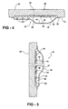
- Figure 4 is a top, cross-sectional view of the invention taken along lines 4-4 of Figure 3 ;
- Figure 5 is a side, cross-sectional view of the invention taken along lines 5-5 of Figure 3 ;
- Figure 6 is a side view of a motor vehicle incorporating the invention that provides additional functionality.
- FIG. 1 a side view of a motor vehicle 10 is shown partially cut away.
- the motor vehicle has a side door 12 that provides access to a passenger compartment 14 of the motor vehicle 10.
- This side door 12 includes a door handle 16 and a key hole 18 for standard locking and unlocking using a key (not shown).
- the motor vehicle 10 also includes an A pillar 20 and a B pillar 22 extending up from a main body 24 of the motor vehicle to a roof 26.
- the B pillar 22 is covered by a cover plate 28.
- the cover plate 28 is a tinted black or dark color polycarbonate or acrylic in standard ambient light conditions.
- standard ambient light conditions include any type of outdoor lighting or the lack thereof. Therefore, the cover plate 28 appears opaque in sunlight, darkness, and artificial, non-coherent light sources, which are typically used to provide lighting in darkness.
- the cover plate 28 covers the B pillar 22 and adds to the overall aesthetic design of the motor vehicle 10. More specifically, the cover plate 28 is used as a part of the overall design of the exterior of the motor vehicle 10.
- the cover plate 28 may cover a portion of the B pillar 22 or it may cover the entire B pillar 22.
- the composition of the cover plate 28 allows the cover plate 28 to act as a "dead front" in that it is opaque with respect to electromagnetic radiation in the visible portion of the spectrum of electromagnetic radiation, but transparent with respect to the radio frequency portion of the spectrum.
- the dead front cover plate 28 is transparent to magnetic radiation as will be discussed in greater detail subsequently.
- the cover plate 28 covers a dead front actuating assembly, generally indicated at 30, and shown in phantom in Figure 1 .
- the dead front actuating assembly 30 is an assembly that allows for the side door 12 to be unlatched and opened without utilizing a key fob entry or a manual key, which is inserted into the key hole 18. Like the key fob actuation, the dead front actuating assembly 30 is commonly referred to as a type of keyless entry. While the dead front actuating assembly 30 is described herein as a keyless entry system, it should be appreciated by those skilled in the art that the dead front actuating assembly 30 may be utilized for any type of system that requires actuation. Such systems may include, but are not limited to, the unlocking of tailgates and liftgates, the activation of appropriate illuminating switches, and the activation or deactivation of any other electronic component incorporated into the motor vehicle 10.
- the cover plate 28 covers the dead front actuating assembly 30, the cover plate 28 provides the dead front feature thereof. More specifically, the cover plate 28 can look like nothing is behind it when the dead front actuating assembly 30 is deactivated.
- the dead front actuating assembly 30 may be placed includes any pillar, driver or passenger side, or any surface that is capable of having a polycarbonate, acrylic or similar construction with the little space therebehind for the dead front actuating assembly 30 to be mounted.
- the location may be on the exterior of the motor vehicle 10, the inside of the passenger compartment 14, or inside an engine storage compartment.
- the dead front actuation assembly 30 described herein could also be used in a number of vehicle interior applications where a completely sealed surface is advantageous or desired, such as door switches (to avoid penetration of the switch box by rain or other external moisture), and center consoles next to cup holders. Another type of use would be to use the non-contact dead front actuating assembly 30 to activate and make itself visible when it is detected that a passenger has occupied a seat.
- the cover plate 28 is shown with the dead front actuating assembly 30 deactivated and activated, respectively.
- the dead front actuating assembly 30 is invisible due to the opaque nature of the cover plate 28 ( Figures 1 and 2 ).
- a key pad 32 is illuminated and visible through the cover plate 28.
- the key pad 32 includes a plurality of switches 34 that are used in a random combination to unlock the latch of the side door 12. It should be appreciated by those skilled in the art that the key pad 32 and the dead front actuating assembly 30 may also be used to lock the side door 12 preventing access to the passenger compartment 14.
- the dead front actuating assembly 30 includes a housing 36 that defines a periphery 38 (best shown in Figure 1 ) and an interior volume 40.
- the housing 36 is fixedly secured to the cover plate 28 at the periphery 38.
- the housing includes a reflective surface 42 designed to reflect as much light generated by the non-contact dead front actuating assembly 30 away therefrom and toward the cover plate 28.
- the cover plate 28 defines an inboard surface 44 and an outboard surface 46.
- the inboard surface 44 is fixedly secured to the motor vehicle 10, whereas the outboard surface 46 is visible to those outside the motor vehicle 10. Therefore, the inboard surface 44 faces the interior volume 40 and the outboard surface 46 is opposite the inboard surface 44 and it is the outboard surface 46 that appears to be opaque to those standing outside the motor vehicle 10 in standard ambient light conditions.
- the switches 34 are operatively connected to the cover plate 28.
- the switches 34 are mounted to a plate 48 and are touch sensitive. More specifically, each of the plurality of switches 34 are activated by touching the cover plate 28 in direct proximity to the specific switch 34 being "pressed” or activated.
- the switches 34 are sensors that detect a change in the capacitance of the cover plate 28 in direct proximity to the location of the particular switch 34.
- the dead front actuating assembly 30 also includes a presence sensor 50.
- the presence sensor 50 identifies when an operator is disposed adjacent the cover plate 28.
- the presence sensor 50 is a touch sensor that is integrated into the plate 48 in which the plurality of switches 34 are located.
- the presence sensor 50 may be mounted to a circuit board and identifies when the operator of the motor vehicle 10 approaches.
- Such a presence sensor 50 may be a transceiver that sends a signal to ping a key fob (not shown) to identify when the key fob enters the space in immediate proximity to the dead front actuating assembly 30, the plurality of switches 34 are illuminated by the dead front actuating assembly 30.
- the presence sensor 50 and the plurality of switches 34 may, in some embodiments, be the same type of sensors. In fact, activating one of the plurality of switches 34 through a touch may act as the presence sensor 50 to activate the non-contact dead front actuating assembly 30. In other instances, the presence sensor 50 and the plurality of switches may be designed to be capacitive sensors, touch sensitive sensors, resistive sensors, temperature sensors, optical scanners or any combination thereof.
- a back light inside the housing 36 illuminates the cover plate 28 such that light passes through the cover plate 28 and out the outboard surface 46 to illuminate the location of the plurality of switches 34 for the operator.
- the back light is generated by a light emitting diode 51.
- LEDs light emitting diodes
- the LEDs 51 direct light toward the interior volume 40 of the housing 36 to be reflected by the reflective surface 42 toward the inboard surface 44 of the cover plate 28.
- the light passes through the plate 48 and the cover plate 28 to be viewed by the operator as modified by a layer of graphics 52.
- the switches 34 and presence sensor 50 are fabricated from electronics that are not, by design, readily visible to the operator. Therefore, the layer of graphics 52 is used to identify the location of each of these switches 34.
- the graphics 52 are not operative in and of themselves, but merely targets used to allow the operator to identify where each of the plurality of switches 34 are located to more accurately and efficiently operate the dead front actuating assembly 30. It is the targets that are visible in Figure 3 . In an alternative embodiment, there are no graphics and the switches 34 are visible through the back lighting in a manner visible to the operator for selection thereby.
- the back light source and delivery mechanism may be any type of light source 51 that will be able to be incorporated that can overcome opaque qualities of the cover plate 28.
- Such examples of light source for the back light 51 include, but are not limited to, sources that generate light through fluorescent, filament, phosphorescent or laser elements. Fiber optics and/or wave guides may direct the light should the source for the back light need to be in a different location.
- the dead front actuating assembly is shown in a side view.
- Connectors 54 mounted to an integrated circuit board 56, connect the dead front actuating assembly 30 to the electronics of the motor vehicle 10 through wires 58 ( Figures 3 and 4 ) to receive power and to communicate with latching assembly associated with the side door 12 to identify when it is appropriate to unlock the side door 12.
- the integrated circuit board 56 includes electronics known in the art for providing exterior combination locks that incorporate the traditional numeric keypad.
- the integrated circuit board 56 includes electronics suitable for providing the necessary voltage to the plurality of switches 34 so the capacitances and changes therewith may be detected. Such changes in capacitance occur when an operator places a finger on the cover plate 28 on or near the location of one of the plurality of switches 34.
- the electronics on the integrated circuit board 56 identify the capacitance change as a selection of a particular location which is identified by the graphics 52.
- the graphics 52 typically represent letters or numbers (as is shown in Figure 3 ).
- the electronics send a signal through the connectors 54 and the wires 58 to have the side door 12 unlatched by the door latch (not shown).
- the motor vehicle 10' does not include a door handle or key hole.
- This motor vehicle 10' utilizes a dead front actuating assembly 30' that can perform multiple functions, e.g. unlock and unlatch the side door 12'. This allows the design of the motor vehicle 10' to be further unencumbered by functional features that detract from the aesthetic qualities of the motor vehicle 10'.
Landscapes
- Physics & Mathematics (AREA)
- General Physics & Mathematics (AREA)
- Engineering & Computer Science (AREA)
- Mechanical Engineering (AREA)
- Lock And Its Accessories (AREA)
- Push-Button Switches (AREA)
- Mechanical Control Devices (AREA)
- Indication Of The Valve Opening Or Closing Status (AREA)
Claims (11)
- Optisch abgeschirmte Betätigungsanordnung (30) zur Betätigung einer Vorrichtung unter normalen Umgebungslichtbedingungen, mit
einem Gehäuse (36), das einen Umfang (38) und einen Innenraum (40) definiert,
einer Deckplatte (28), die starr mit dem Gehäuse (36) an dem Umfang (38) verbunden ist, wobei die Deckplatte (28) eine Innenfläche (44) definiert, die in Richtung des Innenraums (40) und einer entgegengesetzt zu der Innenfläche (44) angeordneten Außenfläche (46) weist, wobei die Außenfläche (46) unter normalen Umgebungslichtbedingungen lichtundurchlässig ist,
einem Schalter (34), der in Wirkverbindung mit der Deckplatte (28) zum Umschalten der Vorrichtung zwischen eingeschaltetem und ausgeschaltetem Zustand steht, gekennzeichnet durch
einen Anwesenheitssensor (50), der erkennt bzw. identifiziert, wenn sich ein Benutzer nahe der Deckplatte (28) befindet, und
eine Hintergrundbeleuchtung (51) in dem Gehäuse (36), um die Deckplatte (28) derart zu beleuchten, dass Licht durch die Deckplatte (28) hindurch und aus der Außenfläche (46) tritt, um einen definierten Bereich des Schalters (34) für den Benutzer zu beleuchten. - Optisch abgeschirmte Betätigungsanordnung nach Anspruch 1, mit einer starr an der Innenfläche (44) befestigten Grafikschablone (52) zur grafischen Identifizierung des Schalters (34), wenn die Hintergrundbeleuchtung (51) eingeschaltet ist.
- Optisch abgeschirmte Betätigungsanordnung nach Anspruch 2, wobei der Anwesenheitssensor (50) ein Berührungssensor ist, der erkennt bzw. identifiziert, wenn der Benutzer die Deckplatte (28) berührt.
- Optisch abgeschirmte Betätigungsanordnung nach Anspruch 3, wobei der Schalter (34) und die Grafikschablone (52) nicht sichtbar sind, wenn die Hintergrundbeleuchtung (51) ausgeschaltet ist.
- Optisch abgeschirmte Betätigungsanordnung nach Anspruch 4, wobei das Gehäuse (36) eine reflektierende Oberfläche umfasst, um einen Großteil des von der Hintergrundbeleuchtung (51) emittierten Lichts an der Deckplatte (28) zu reflektieren.
- Optisch abgeschirmte Betätigungsanordnung nach Anspruch 5, wobei die Hintergrundbeleuchtung (51) eine lichtemittierende Diode (51) ist.
- Optisch abgeschirmte Betätigungsanordnung nach Anspruch 6, die eine Mehrzahl von Schaltern (34) umfasst.
- Optisch abgeschirmte Betätigungsanordnung nach Anspruch 7, wobei die Hintergrundbeleuchtung (51) eine Mehrzahl von lichtemittierenden Dioden (51) umfasst.
- Optisch abgeschirmte Betätigungsanordnung nach Anspruch 8, wobei sich der Berührungssensor über ein von dem Umfang (38) des Gehäuses (36) definiertes Gebiet erstreckt.
- Optisch abgeschirmte Betätigungsanordnung nach einem der Ansprüche 7 bis 9, wobei die optisch abgeschirmte Betätigungsanordnung einen schlüssellosen Einstieg in einen Fahrgastraum (14) eines Kraftfahrzeugs (10) durch Entriegeln eines Schlosses einer Tür (12) des Kraftfahrzeugs (10) bereitstellt und wobei
die Mehrzahl von Schaltern (34) in Wirkverbindung mit der Deckplatte (28) steht, um das Schloss des Kraftfahrzeugs (10) zu verriegeln und entriegeln, und
die Hintergrundbeleuchtung (51) im Inneren des Gehäuses (36) die Deckplatte (28) derart beleuchtet, dass das Licht durch die Deckplatte (28) hindurch und aus der Außenfläche (46) tritt, um die Mehrzahl von Schaltern (34) zu beleuchten und dem Benutzer zu ermöglichen, eine Kombination aus der Mehrzahl von Schaltern (34) zum Entriegeln und Verriegeln des Kraftfahrzeugs (10) zu wählen. - Optisch abgeschirmte Betätigungsanordnung nach einem der Ansprüche 8 bis 10, wobei der Schalter (34) und die Grafikschablone (52) nicht sichtbar sind, wenn die Mehrzahl von lichtemittierenden Dioden (51) ausgeschaltet ist.
Applications Claiming Priority (2)
| Application Number | Priority Date | Filing Date | Title |
|---|---|---|---|
| US63304904P | 2004-12-03 | 2004-12-03 | |
| PCT/US2005/043824 WO2006060745A2 (en) | 2004-12-03 | 2005-12-05 | Non-contact dead front actuation system |
Publications (2)
| Publication Number | Publication Date |
|---|---|
| EP1817784A2 EP1817784A2 (de) | 2007-08-15 |
| EP1817784B1 true EP1817784B1 (de) | 2009-04-29 |
Family
ID=36565822
Family Applications (1)
| Application Number | Title | Priority Date | Filing Date |
|---|---|---|---|
| EP05852908A Ceased EP1817784B1 (de) | 2004-12-03 | 2005-12-05 | Berührungsloses betätigungssystem mit geerdeter oberfläche |
Country Status (5)
| Country | Link |
|---|---|
| US (2) | US7637631B2 (de) |
| EP (1) | EP1817784B1 (de) |
| CA (1) | CA2589576C (de) |
| DE (1) | DE602005014266D1 (de) |
| WO (1) | WO2006060745A2 (de) |
Families Citing this family (33)
| Publication number | Priority date | Publication date | Assignee | Title |
|---|---|---|---|---|
| EP1817784B1 (de) * | 2004-12-03 | 2009-04-29 | Magna International Inc | Berührungsloses betätigungssystem mit geerdeter oberfläche |
| DE102007002700A1 (de) * | 2007-01-18 | 2008-07-24 | Daimler Ag | Kraftfahrzeug mit einer eine Türöffnung verschließenden Fahrzeugtür |
| CA2699681C (en) | 2007-09-17 | 2016-05-10 | Magna International Inc. | Touchless keyless entry keypad integrated with electroluminescence backlight |
| US20100013269A1 (en) * | 2008-07-15 | 2010-01-21 | Guardian Industries Corp. | B-pillar having electronic control device, and/or method of making the same |
| US8648832B2 (en) * | 2008-09-25 | 2014-02-11 | Stoneridge Control Devices, Inc. | Touch sensor system and method |
| CA2724487A1 (en) | 2009-12-08 | 2011-06-08 | Magna International Inc. | Appliance doors having integrated lighting and controls |
| EP2748516B1 (de) * | 2011-10-18 | 2018-01-10 | Philips Lighting Holding B.V. | Leuchte mit strahlteilung und beleuchtungssystem |
| WO2013076641A1 (en) | 2011-11-22 | 2013-05-30 | Koninklijke Philips Electronics N.V. | An optical redirection layer for a luminaire |
| US20130229820A1 (en) * | 2012-03-01 | 2013-09-05 | GM Global Technology Operations LLC | Vehicle body side lighting |
| US10515489B2 (en) | 2012-05-23 | 2019-12-24 | Enterprise Holdings, Inc. | Rental/car-share vehicle access and management system and method |
| US8768565B2 (en) | 2012-05-23 | 2014-07-01 | Enterprise Holdings, Inc. | Rental/car-share vehicle access and management system and method |
| US9499128B2 (en) | 2013-03-14 | 2016-11-22 | The Crawford Group, Inc. | Mobile device-enhanced user selection of specific rental vehicles for a rental vehicle reservation |
| US9220394B2 (en) | 2013-08-15 | 2015-12-29 | Whirlpool Corporation | LED console assembly with light reflector |
| US9499127B2 (en) | 2014-06-16 | 2016-11-22 | Magna Closures Inc. | Swipe and tap verification for entry system |
| US20170371036A1 (en) * | 2015-02-06 | 2017-12-28 | Delphi Technologies, Inc. | Autonomous vehicle with unobtrusive sensors |
| US10678261B2 (en) | 2015-02-06 | 2020-06-09 | Aptiv Technologies Limited | Method and apparatus for controlling an autonomous vehicle |
| US20180012492A1 (en) | 2015-02-06 | 2018-01-11 | Delphi Technologies, Inc. | Method of automatically controlling an autonomous vehicle based on electronic messages from roadside infrastructure or other vehicles |
| FR3037543B1 (fr) * | 2015-06-19 | 2017-06-02 | Mecaplast France | Procede et dispositif de deverrouillage d’un vehicule |
| WO2018013557A1 (en) | 2016-07-11 | 2018-01-18 | Shanghai Yanfeng Jinqiao Automotive Trim Systems Co. Ltd | Vehicle interior component |
| US10279659B2 (en) * | 2017-01-12 | 2019-05-07 | Ford Global Technologies, Llc | Vehicle keypad formed in a window |
| US10137857B1 (en) * | 2017-08-22 | 2018-11-27 | Ford Global Technologies, Llc | Vehicle unlocking systems, devices, and methods |
| US10300889B2 (en) | 2017-09-08 | 2019-05-28 | Ford Global Technologies, Llc | Iris-detection alignment for vehicle feature activation |
| US10077576B1 (en) | 2017-10-12 | 2018-09-18 | Ford Global Technologies, Llc | Vehicle keypad illumination assembly and method |
| US11136000B2 (en) | 2017-11-17 | 2021-10-05 | Magna Closures Inc. | Touch and gesture pad for swipe/tap entry verification system |
| US10124767B1 (en) | 2018-01-29 | 2018-11-13 | Ford Global Technologies, Llc | Vehicle exterior keypad having interior lamp |
| US11542731B2 (en) | 2018-07-03 | 2023-01-03 | Magna Closures Inc. | Smart handle assembly with force-based sensor and backup energy source |
| EP3824376B1 (de) | 2018-07-18 | 2025-04-09 | Shanghai Yanfeng Jinqiao Automotive Trim Systems Co. Ltd | Fahrzeuginnenkomponente |
| WO2021011536A1 (en) | 2019-07-15 | 2021-01-21 | Shanghai Yanfeng Jinqiao Automotive Trim Systems Co. Ltd. | Vehicle interior component |
| US11542732B2 (en) | 2019-11-14 | 2023-01-03 | Magna Mirrors Of America, Inc. | Handle assembly for vehicular closure panels having integrated antenna and force sensor configuration |
| DE102020102897A1 (de) | 2020-02-05 | 2021-08-05 | Huf Hülsbeck & Fürst Gmbh & Co. Kg | Modulare Betätigungsvorrichtung, Fahrzeug, sowie Verfahren |
| DE102020102887A1 (de) | 2020-02-05 | 2021-08-05 | Huf Hülsbeck & Fürst Gmbh & Co. Kg | Betätigungsvorrichtung mit Verkleidungselement, Fahrzeug, sowie Verfahren |
| US12546150B2 (en) * | 2021-01-07 | 2026-02-10 | Ford Global Technologies, Llc | Door assembly for motor vehicle |
| US20250320757A1 (en) * | 2024-04-10 | 2025-10-16 | Tesla, Inc. | Door assembly |
Family Cites Families (24)
| Publication number | Priority date | Publication date | Assignee | Title |
|---|---|---|---|---|
| US1777866A (en) * | 1929-04-18 | 1930-10-07 | Steiss John Gordon | Display apparatus |
| US2595331A (en) * | 1950-01-30 | 1952-05-06 | Paul F Calihan | Combination vision mirror and signaling device |
| US3499240A (en) * | 1967-02-21 | 1970-03-10 | Us Navy | Illuminated grid for backlighted plotting boards |
| US3487206A (en) * | 1967-04-10 | 1969-12-30 | Ford Motor Co | Concealed vehicle running light assembly |
| US3829850A (en) * | 1971-12-17 | 1974-08-13 | Tyco Laboratories Inc | Proximity detector |
| US4205325A (en) * | 1977-12-27 | 1980-05-27 | Ford Motor Company | Keyless entry system |
| BE870387A (fr) * | 1978-09-11 | 1979-01-02 | Lecloux Jacques | Commutateur a cinetisme |
| US4821019A (en) * | 1987-01-08 | 1989-04-11 | Taylor Keith H | Mirror assembly including an image forming lamp |
| US5522623A (en) * | 1990-03-29 | 1996-06-04 | Technical Systems Corp. | Coded identification card and other standardized documents |
| JP2628819B2 (ja) * | 1992-04-01 | 1997-07-09 | 河西工業株式会社 | ドアトリム用ユニットパネル |
| FR2694778B1 (fr) * | 1992-08-11 | 1995-04-14 | Smh Management Services Ag | Dispositif de sécurité destiné à l'ouverture et/ou à la fermeture de porte notamment pour un véhicule automobile. |
| GB9522135D0 (en) * | 1995-10-30 | 1996-01-03 | John Mcgavigan Holdings Limite | Display panels |
| DE19620059B4 (de) * | 1996-05-20 | 2004-12-23 | Ifm Electronic Gmbh | Schaltungsanordnung zum Entriegeln mindestens eines Türschlosses eines Kraftfahrzeugs |
| AUPP277798A0 (en) * | 1998-04-03 | 1998-04-30 | Robert Bosch Gmbh | Detection system |
| US6774505B1 (en) * | 1998-07-17 | 2004-08-10 | Lear Automotive Dearborn, Inc. | Vehicle switch assembly with proximity activated illumination |
| US6288652B1 (en) * | 1999-01-11 | 2001-09-11 | Ford Global Technologies, Inc. | Digitally encoded keyless entry keypad switch |
| US6727800B1 (en) * | 2000-11-01 | 2004-04-27 | Iulius Vivant Dutu | Keyless system for entry and operation of a vehicle |
| US6854870B2 (en) * | 2001-06-30 | 2005-02-15 | Donnelly Corporation | Vehicle handle assembly |
| US6897390B2 (en) * | 2001-11-20 | 2005-05-24 | Touchsensor Technologies, Llc | Molded/integrated touch switch/control panel assembly and method for making same |
| US7034655B2 (en) * | 2002-08-06 | 2006-04-25 | Tri/Mark Corporation | Keypad module and method for electronic access security and keyless entry of a vehicle |
| US6789003B2 (en) * | 2002-08-06 | 2004-09-07 | Tri/Mark Corporation | Control module for providing access, monitoring vehicles states, and control of a vehicle |
| US7063471B2 (en) * | 2003-05-20 | 2006-06-20 | Essex Electronics, Inc. | Access control apparatus |
| TWM246202U (en) * | 2003-05-20 | 2004-10-11 | Exon Science Inc | Vehicular door handle module |
| EP1817784B1 (de) * | 2004-12-03 | 2009-04-29 | Magna International Inc | Berührungsloses betätigungssystem mit geerdeter oberfläche |
-
2005
- 2005-12-05 EP EP05852908A patent/EP1817784B1/de not_active Ceased
- 2005-12-05 CA CA 2589576 patent/CA2589576C/en not_active Expired - Fee Related
- 2005-12-05 DE DE200560014266 patent/DE602005014266D1/de not_active Expired - Lifetime
- 2005-12-05 WO PCT/US2005/043824 patent/WO2006060745A2/en not_active Ceased
-
2007
- 2007-05-24 US US11/805,939 patent/US7637631B2/en not_active Expired - Lifetime
-
2009
- 2009-11-06 US US12/590,389 patent/US20100053958A1/en not_active Abandoned
Also Published As
| Publication number | Publication date |
|---|---|
| DE602005014266D1 (de) | 2009-06-10 |
| CA2589576C (en) | 2014-07-08 |
| EP1817784A2 (de) | 2007-08-15 |
| WO2006060745A2 (en) | 2006-06-08 |
| US20100053958A1 (en) | 2010-03-04 |
| WO2006060745A3 (en) | 2006-11-09 |
| US7637631B2 (en) | 2009-12-29 |
| CA2589576A1 (en) | 2006-08-06 |
| US20070295043A1 (en) | 2007-12-27 |
Similar Documents
| Publication | Publication Date | Title |
|---|---|---|
| EP1817784B1 (de) | Berührungsloses betätigungssystem mit geerdeter oberfläche | |
| US8400265B2 (en) | Touchless keyless entry keypad integrated with electroluminescence backlight | |
| US12281503B2 (en) | Vehicular exterior door handle assembly | |
| US10017977B2 (en) | Keyless entry assembly having capacitance sensor operative for detecting objects | |
| US9575481B2 (en) | Fascia panel assembly having capacitance sensor operative for detecting objects | |
| US7576631B1 (en) | Vehicular keyless entry system incorporating textual representation of the vehicle or user of the vehicle | |
| US9797179B2 (en) | Vehicle assembly having a capacitive sensor | |
| US9199608B2 (en) | Keyless entry assembly having capacitance sensor operative for detecting objects | |
| US9845629B2 (en) | Vehicle keyless entry assembly having capacitance sensor operative for detecting objects | |
| US7255466B2 (en) | Illuminated keyless entry control device | |
| US8567976B2 (en) | Appliance doors having integrated lighting and controls | |
| US20030031025A1 (en) | Vehicle handle assembly | |
| US10954709B2 (en) | Vehicle assembly having a capacitive sensor | |
| US20080211626A1 (en) | Passive entry sensor system | |
| US10279659B2 (en) | Vehicle keypad formed in a window | |
| JP3159984U (ja) | 自動車ドアハンドルの後付け用押しボタンカバーキット | |
| US20050190040A1 (en) | Keyless entry system in side-view mirror | |
| WO1999058795A1 (en) | Tap sensitive keypad assembly |
Legal Events
| Date | Code | Title | Description |
|---|---|---|---|
| PUAI | Public reference made under article 153(3) epc to a published international application that has entered the european phase |
Free format text: ORIGINAL CODE: 0009012 |
|
| 17P | Request for examination filed |
Effective date: 20070601 |
|
| AK | Designated contracting states |
Kind code of ref document: A2 Designated state(s): DE FR GB |
|
| 17Q | First examination report despatched |
Effective date: 20080102 |
|
| DAX | Request for extension of the european patent (deleted) | ||
| RBV | Designated contracting states (corrected) |
Designated state(s): DE FR GB |
|
| GRAP | Despatch of communication of intention to grant a patent |
Free format text: ORIGINAL CODE: EPIDOSNIGR1 |
|
| GRAS | Grant fee paid |
Free format text: ORIGINAL CODE: EPIDOSNIGR3 |
|
| GRAA | (expected) grant |
Free format text: ORIGINAL CODE: 0009210 |
|
| AK | Designated contracting states |
Kind code of ref document: B1 Designated state(s): DE FR GB |
|
| REG | Reference to a national code |
Ref country code: GB Ref legal event code: FG4D |
|
| REF | Corresponds to: |
Ref document number: 602005014266 Country of ref document: DE Date of ref document: 20090610 Kind code of ref document: P |
|
| PLBE | No opposition filed within time limit |
Free format text: ORIGINAL CODE: 0009261 |
|
| STAA | Information on the status of an ep patent application or granted ep patent |
Free format text: STATUS: NO OPPOSITION FILED WITHIN TIME LIMIT |
|
| 26N | No opposition filed |
Effective date: 20100201 |
|
| REG | Reference to a national code |
Ref country code: FR Ref legal event code: PLFP Year of fee payment: 11 |
|
| REG | Reference to a national code |
Ref country code: DE Ref legal event code: R082 Ref document number: 602005014266 Country of ref document: DE Representative=s name: GLAWE DELFS MOLL PARTNERSCHAFT MBB VON PATENT-, DE |
|
| REG | Reference to a national code |
Ref country code: FR Ref legal event code: PLFP Year of fee payment: 12 |
|
| REG | Reference to a national code |
Ref country code: FR Ref legal event code: PLFP Year of fee payment: 13 |
|
| PGFP | Annual fee paid to national office [announced via postgrant information from national office to epo] |
Ref country code: DE Payment date: 20181120 Year of fee payment: 14 |
|
| PGFP | Annual fee paid to national office [announced via postgrant information from national office to epo] |
Ref country code: GB Payment date: 20181205 Year of fee payment: 14 Ref country code: FR Payment date: 20181121 Year of fee payment: 14 |
|
| REG | Reference to a national code |
Ref country code: DE Ref legal event code: R119 Ref document number: 602005014266 Country of ref document: DE |
|
| GBPC | Gb: european patent ceased through non-payment of renewal fee |
Effective date: 20191205 |
|
| PG25 | Lapsed in a contracting state [announced via postgrant information from national office to epo] |
Ref country code: GB Free format text: LAPSE BECAUSE OF NON-PAYMENT OF DUE FEES Effective date: 20191205 Ref country code: FR Free format text: LAPSE BECAUSE OF NON-PAYMENT OF DUE FEES Effective date: 20191231 Ref country code: DE Free format text: LAPSE BECAUSE OF NON-PAYMENT OF DUE FEES Effective date: 20200701 |