EP1818138B1 - Bras de mesure d'outil pour un broyeur - Google Patents
Bras de mesure d'outil pour un broyeur Download PDFInfo
- Publication number
- EP1818138B1 EP1818138B1 EP07101882A EP07101882A EP1818138B1 EP 1818138 B1 EP1818138 B1 EP 1818138B1 EP 07101882 A EP07101882 A EP 07101882A EP 07101882 A EP07101882 A EP 07101882A EP 1818138 B1 EP1818138 B1 EP 1818138B1
- Authority
- EP
- European Patent Office
- Prior art keywords
- tool
- support bar
- plate
- grindstone
- edge
- Prior art date
- Legal status (The legal status is an assumption and is not a legal conclusion. Google has not performed a legal analysis and makes no representation as to the accuracy of the status listed.)
- Active
Links
Images


Classifications
-
- B—PERFORMING OPERATIONS; TRANSPORTING
- B24—GRINDING; POLISHING
- B24B—MACHINES, DEVICES, OR PROCESSES FOR GRINDING OR POLISHING; DRESSING OR CONDITIONING OF ABRADING SURFACES; FEEDING OF GRINDING, POLISHING, OR LAPPING AGENTS
- B24B3/00—Sharpening cutting edges, e.g. of tools; Accessories therefor, e.g. for holding the tools
- B24B3/36—Sharpening cutting edges, e.g. of tools; Accessories therefor, e.g. for holding the tools of cutting blades
- B24B3/38—Sharpening cutting edges, e.g. of tools; Accessories therefor, e.g. for holding the tools of cutting blades for planing wood, e.g. cutter blades
-
- B—PERFORMING OPERATIONS; TRANSPORTING
- B23—MACHINE TOOLS; METAL-WORKING NOT OTHERWISE PROVIDED FOR
- B23Q—DETAILS, COMPONENTS, OR ACCESSORIES FOR MACHINE TOOLS, e.g. ARRANGEMENTS FOR COPYING OR CONTROLLING; MACHINE TOOLS IN GENERAL CHARACTERISED BY THE CONSTRUCTION OF PARTICULAR DETAILS OR COMPONENTS; COMBINATIONS OR ASSOCIATIONS OF METAL-WORKING MACHINES, NOT DIRECTED TO A PARTICULAR RESULT
- B23Q3/00—Devices holding, supporting, or positioning work or tools, of a kind normally removable from the machine
- B23Q3/02—Devices holding, supporting, or positioning work or tools, of a kind normally removable from the machine for mounting on a work-table, tool-slide, or analogous part
- B23Q3/10—Auxiliary devices, e.g. bolsters, extension members
-
- B—PERFORMING OPERATIONS; TRANSPORTING
- B24—GRINDING; POLISHING
- B24B—MACHINES, DEVICES, OR PROCESSES FOR GRINDING OR POLISHING; DRESSING OR CONDITIONING OF ABRADING SURFACES; FEEDING OF GRINDING, POLISHING, OR LAPPING AGENTS
- B24B3/00—Sharpening cutting edges, e.g. of tools; Accessories therefor, e.g. for holding the tools
- B24B3/34—Sharpening cutting edges, e.g. of tools; Accessories therefor, e.g. for holding the tools of turning or planing tools or tool bits, e.g. gear cutters
-
- B—PERFORMING OPERATIONS; TRANSPORTING
- B24—GRINDING; POLISHING
- B24B—MACHINES, DEVICES, OR PROCESSES FOR GRINDING OR POLISHING; DRESSING OR CONDITIONING OF ABRADING SURFACES; FEEDING OF GRINDING, POLISHING, OR LAPPING AGENTS
- B24B3/00—Sharpening cutting edges, e.g. of tools; Accessories therefor, e.g. for holding the tools
- B24B3/36—Sharpening cutting edges, e.g. of tools; Accessories therefor, e.g. for holding the tools of cutting blades
-
- B—PERFORMING OPERATIONS; TRANSPORTING
- B24—GRINDING; POLISHING
- B24B—MACHINES, DEVICES, OR PROCESSES FOR GRINDING OR POLISHING; DRESSING OR CONDITIONING OF ABRADING SURFACES; FEEDING OF GRINDING, POLISHING, OR LAPPING AGENTS
- B24B41/00—Component parts such as frames, beds, carriages, headstocks
- B24B41/06—Work supports, e.g. adjustable steadies
- B24B41/066—Work supports, e.g. adjustable steadies adapted for supporting work in the form of tools, e.g. drills
-
- B—PERFORMING OPERATIONS; TRANSPORTING
- B27—WORKING OR PRESERVING WOOD OR SIMILAR MATERIAL; NAILING OR STAPLING MACHINES IN GENERAL
- B27G—ACCESSORY MACHINES OR APPARATUS FOR WORKING WOOD OR SIMILAR MATERIALS; TOOLS FOR WORKING WOOD OR SIMILAR MATERIALS; SAFETY DEVICES FOR WOOD WORKING MACHINES OR TOOLS
- B27G23/00—Gauging means specially designed for adjusting of tools or guides, e.g. adjusting cutting blades in cutter blocks
-
- G—PHYSICS
- G01—MEASURING; TESTING
- G01B—MEASURING LENGTH, THICKNESS OR SIMILAR LINEAR DIMENSIONS; MEASURING ANGLES; MEASURING AREAS; MEASURING IRREGULARITIES OF SURFACES OR CONTOURS
- G01B3/00—Measuring instruments characterised by the use of mechanical techniques
- G01B3/56—Gauges for measuring angles or tapers, e.g. conical calipers
Definitions
- the present invention relates to a device, hereinafter also referred to as a tool setter, for setting the position of a support bar, as per the preamble of claim 1.
- a device hereinafter also referred to as a tool setter
- An example of such a device is disclosed by US 5 172 484 A .
- Edge tools for example for woodworking, especially woodturning tools, have to be sharp for obtaining optimum results.
- Sharpening can be performed by means of a rotating grindstone in a grinding machine.
- the sharpening is preferably carried out by means of a jig, in which the tool is attached and which is supported by a support bar of the machine. In this way an exact replication of the edge shape and edge angle of a previous sharpening can be obtained.
- the shape of the edge is exactly the same after each re-sharpening, so that the tool always behaves in the same way at work.
- the wood surface becomes finer and may not need sanding or the like.
- the distance between the support bar and the grindstone has been established by means of a wooden spacer made by the user at the first sharpening of a tool. This is a rather awkward process, also with an inherent risk of then loosing a particular wooden spacer. Different spacers may be needed for different tools. Each spacer will lead to a copying of the edge geometry obtained at a previous sharpening. The precision of the result is depending on the skill and accuracy of the user. Further, the spacer can not be used with a grindstone with another diameter than the original one, if a replicated edge angle is desired.
- the main object of the invention is to enable a proper, replicated setting by means of a commercially available device, also with a grindstone of another diameter than of the one previously used, with a simpler and cheaper device than the one shown in US 5 172 484 .
- Another object of the invention is to attain a device for simplifying the setting of the support bar with the highest possible accuracy.
- the means for defining the contact points can be metal discs attached in the plate of plastic.
- the plate may be provided with at least one further hole for optional connection to the support bar.
- a replicated sharpening result is dependent on the use of the same protrusion of the tool from a jig utilized at grinding.
- the plate is provided with a projection forming shoulders at different distances from an edge of the plate.
- the plate may be provided with magnets for attachment of the device to a metal surface, for example the grinding machine, so as to prevent it from being lost.
- An edge of the plate may be provided with grooves for checking an edge angle of a tool, for example before and after a sharpening.
- a conventional grinding machine 1 is shown in Fig 1 .
- the machine is provided with a circular grindstone 2 driven by an electric motor in the machine.
- the machine is provided with a cylindrical support bar 3.
- the purpose of the support bar 3 is to serve as a guiding means, as will appear below.
- the distance between the grindstone 2 and the support bar 3 parallel therewith may be adjusted by the slidable mounting of the support bar 3 to the grinding machine 1.
- the distance may be fixed by a set screw 3' on the machine.
- the grinding machine 1 may also be provided with a honing wheel 4.
- edge tools especially woodturning tools, such as chisels and gouges, most importantly spindle gouges, bowl gouges and plain or oval skew chisels
- edge tools especially woodturning tools, such as chisels and gouges, most importantly spindle gouges, bowl gouges and plain or oval skew chisels
- a jig 5 to be briefly described with reference to Fig 2 .
- the jig has a base member 6 with a support bar tube 7 attached perpendicularily thereto.
- the inner diameter of the tube 7 corresponds to the outer diameter of the support bar 3.
- a tool holder 8 is pivotally attached to the base member 6, and the relative position between these two parts may be locked by means of a lock screw 9.
- a tool received in the tool holder 8 may be held in position by means of a holding screw 10.
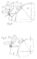
- Fig 3 illustrates the sharpening of a woodturning tool 12, in the shown instance a bowl gouge, by means of the grindstone 2.
- the tool 12 is fastened in the jig 5, which is slid onto the support bar 3, attached in the grinding machine 1 ( Fig 1 ). It is assumed throughout the following description that the base member 6 and the tool holder 8 ( Fig 2 ) of the jig 5 are locked to each other, in the present case forming an angle of 110° with each other.
- a certain edge angle ⁇ of the tool can be obtained, provided that the correct distance d between the grindstone 2 and the support bar 3 is set.
- the edge angle ⁇ is of great importance for the work with the tool, it imperative to obtain the same edge angle at a re-sharpening of the tool.
- this is obtained by setting the support bar 3 at the same distance d from the grindstone as at the previous sharpening(s) (provided that the tool 12 is fastened to the jig 5 with the same protrusion P as earlier).
- the grindstone 2 has a diameter of 250 mm. With the described jig setting and tool protrusion, the distance d will be about 51,5 mm for a desired edge angle ⁇ of 45°. If on the other hand, as illustrated in Fig 4 , the grindstone has a diameter (possibly after wear) of only 200 mm, the desired edge angle ⁇ of 45° will be obtained with a different distance d of about 57 mm.
- a device or tool setter 14 may be used for setting the correct position for the support bar 3 in relation to the grindstone 2.
- this tool setter 14 which will be further described below under reference to Figs 6 and 7 , is a flat utensil with two spaced-apart contact points 15 for application against the grindstone 2 and with at least one circular hole 16 for engagement with the support bar 3.
- the tool setter 14 is slid onto the bar 3 by its hole 16, whereupon the position of the support bar 3 is adjusted, until both the two contact points 15 bear against the surface of the grindstone 2, and the support bar 3 is locked into the set position.
- the tool setter 14 is removed, and the jig 5 with the tool 12 attached therein (with the proper protrusion) is mounted on the support bar 3, whereupon the tool 12 can be re-sharpened with the desired edge angle.
- the geometry shown and described with relation to Figs 3 and 4 is based on the distance d between the bar and the grindstone. However, it may also be defined - as in Fig 5 - as a perpendicular distance d' between a grindstone radius (intermediate the two contact points 15) and the support bar 3. Reverting back to Fig 3 , this distance d' is also the distance between the support bar 3 and the engagement of the tool 12 with the grindstone 2.
- the tool setter 14 is shown in Figs 6 and 7 .
- it may in a practical embodiment consist of a card or plate preferably made of plastic with a generally parallel trapezoid shape. It is provided with two metal discs 15A (for defining the contact points 15 mentioned above). It is also provided with circular holes 16 and 16'.
- the first or left hole 16 has been mentioned above, and the second or right hole 16' has the purpose of enabling sharpening with different parameters (edge angle, type of tool, etc). It is presently felt that two holes 16, 16' satisfy normal needs, but it is of course possible to provide further holes.
- the protrusion P of the tool 12 from the jig 5 is of importance for the obtained replicated result.
- An accurate setting of a desired protrusion P may be obtained in that the rear side of the tool setter 14 - as is shown in Fig 7 - is provided with a projection 17, forming for example three shoulders 17A, 17B and 17C at a distance of for example 75 mm, 65 mm and 55 mm, respectively, from the right hand edge of the tool setter 14 in Fig 7 .
- the opposite or front side of the tool setter 14 is preferably at this edge provided with a ledge 18 for supporting engagement with a suitable edge of a table or the like.
- Magnets 19 for holding or storing the tool setter 14 on a metal surface, for example the grinding machine 1, ready for easy access may be provided on the rear side of the tool setter 14, as is indicated in Fig 7 .
- Grooves 20 for checking edge angles may be provided at an edge of the tool setter 14.
- the tool setter 14 may on free surfaces be provided with appropriate text and illustrations for guiding the user about proper settings for different tools. Consultations with many experienced woodturners have shown that with a tool setter 14 having two holes 16 and 16' and having directions for use of the three protrusions P of 55, 65 and 75 mm, tool shapes and edge angles that can satisfy most needs will be obtained.
- the tool setter 14 has been shown as being provided with two fixed metal discs 15A and two fixed holes 16 and 16'. Deviations are possible within the scope of the appended claims, for example with regard to the number and positions of the support bar holes. Also, it is possible to provide for adjustability for the positions of both the contact points (metal discs) and the support bar connection means (holes).
Landscapes
- Engineering & Computer Science (AREA)
- Mechanical Engineering (AREA)
- Life Sciences & Earth Sciences (AREA)
- Wood Science & Technology (AREA)
- Physics & Mathematics (AREA)
- General Physics & Mathematics (AREA)
- Forests & Forestry (AREA)
- Finish Polishing, Edge Sharpening, And Grinding By Specific Grinding Devices (AREA)
Claims (6)
- Dispositif pour régler la position d'une barre de support (3), connecté de manière à pouvoir être ajusté à une machine d'aiguisage (1), en relation avec une meule rotative (2) de la machine pour obtenir un angle de bord souhaité (α) d'un outil (12) supporté, pour être aiguisé, par la barre de support, le dispositif comprenant une carte ou plaque (14) avec des moyens (15A) pour définir deux points de contact (15) avec la meule (2), caractérisé en ce que ladite carte ou plaque (14) est munie d'un trou (16) pour une connexion pivotante avec la barre de support (3).
- Dispositif selon la revendication 1, dans lequel les moyens pour définir les points de contact (15) sont des disques métalliques (15A) fixés dans la plaque de plastique.
- Dispositif selon la revendication 2, dans lequel la plaque (14) est munie d'au moins un autre trou (16') pour une connexion optionnelle avec la barre de support (3).
- Dispositif selon la revendication 2, dans lequel la plaque (14) est munie d'un appendice (17) formant des épaulements (17A-C) à des distances différentes d'un bord de la plaque pour régler une protubérance (P) pour un outil (12) à aiguiser.
- Dispositif selon la revendication 2, dans lequel la plaque (14) est munie d'aimants (19) pour la fixation du dispositif à une surface métallique.
- Dispositif selon la revendication 2, dans lequel un bord de la plaque (14) est muni de rainures (20) pour contrôler un angle de bord (α) d'un outil (12).
Applications Claiming Priority (1)
| Application Number | Priority Date | Filing Date | Title |
|---|---|---|---|
| SE0600292A SE529606C2 (sv) | 2006-02-10 | 2006-02-10 | Verktygsinställare för en slipmaskin |
Publications (2)
| Publication Number | Publication Date |
|---|---|
| EP1818138A1 EP1818138A1 (fr) | 2007-08-15 |
| EP1818138B1 true EP1818138B1 (fr) | 2010-04-28 |
Family
ID=38006861
Family Applications (1)
| Application Number | Title | Priority Date | Filing Date |
|---|---|---|---|
| EP07101882A Active EP1818138B1 (fr) | 2006-02-10 | 2007-02-07 | Bras de mesure d'outil pour un broyeur |
Country Status (4)
| Country | Link |
|---|---|
| US (3) | US7686678B2 (fr) |
| EP (1) | EP1818138B1 (fr) |
| DE (1) | DE602007006070D1 (fr) |
| SE (1) | SE529606C2 (fr) |
Cited By (2)
| Publication number | Priority date | Publication date | Assignee | Title |
|---|---|---|---|---|
| EP2946881A1 (fr) | 2014-05-22 | 2015-11-25 | Tormek AB | Carter de machine de meulage pour meuleuse |
| WO2023169834A1 (fr) | 2022-03-07 | 2023-09-14 | Tormek Ab | Dispositif de réglage d'angle de meulage, système de meulage et procédé de réglage d'un angle de meulage |
Families Citing this family (8)
| Publication number | Priority date | Publication date | Assignee | Title |
|---|---|---|---|---|
| SE529606C2 (sv) * | 2006-02-10 | 2007-10-02 | Tj Utveckling Ab | Verktygsinställare för en slipmaskin |
| RU2459693C1 (ru) * | 2008-06-26 | 2012-08-27 | Ч Утвекклинг Аб | Устройство для заточки вершины спирального сверла и способ его использования |
| US20100248594A1 (en) * | 2009-03-31 | 2010-09-30 | Darrel Nish | Setup tool for grinder sharpening jigs |
| SE539239C2 (en) * | 2015-02-18 | 2017-05-23 | Tormek Ab | Adjustable grinding jig |
| DE202019101756U1 (de) | 2019-03-27 | 2019-04-04 | Janfried Seeburger | Schleifhilfe und Werkzeugmaschine mit Schleifhilfe |
| SE543585C2 (en) | 2019-04-05 | 2021-04-06 | Tormek Ab | An arrangement for grinding edged tools |
| SE543256C2 (en) | 2019-04-05 | 2020-11-03 | Tormek Ab | A grinding jig for a blade tool |
| DE102020002778B4 (de) | 2020-05-09 | 2023-04-27 | Jana Ehrle | Vorrichtung zur Montage an eine Doppelschleifmaschine oder einen Schleifbock zum manuellen Scharfschleifen von Spiralbohrern Typ N in der Größe von 1,00 bis 10,00 mm |
Family Cites Families (51)
| Publication number | Priority date | Publication date | Assignee | Title |
|---|---|---|---|---|
| US2125545A (en) * | 1938-02-14 | 1938-08-02 | Marcus A Gartner | Gauge |
| US3855735A (en) | 1970-12-18 | 1974-12-24 | Tokyo Bearing Mfg Co Ltd | Dimensional control gauge for internal grinders |
| US3942253A (en) | 1972-03-14 | 1976-03-09 | Iosif Davydovich Gebel | Device for measuring deviation of the normal section profile of a part from the round shape |
| JPS5145036Y2 (fr) | 1972-10-19 | 1976-11-01 | ||
| GB1427957A (en) * | 1973-06-23 | 1976-03-10 | Neil Holdings Ltd James | Devices for use in re-sharpening fluted cutting tools and the like |
| US4106241A (en) | 1976-10-28 | 1978-08-15 | Fisk James C | Grinding gauge support |
| CH614653A5 (fr) | 1977-03-15 | 1979-12-14 | Schenker Ag Maschinen | |
| US4244118A (en) | 1979-06-27 | 1981-01-13 | Chester Matuszak | Alignment device for hand held cutting tools |
| US4291466A (en) | 1979-09-14 | 1981-09-29 | The Valeron Corporation | Transducer for measuring workpieces |
| US4338749A (en) * | 1980-07-21 | 1982-07-13 | Kiser Robert E | Toolholder |
| IT1135893B (it) | 1980-12-23 | 1986-08-27 | Finike Italiana Marposs | Dispositivo di misura per il controllo dimensionale di un pezzo meccanico |
| DE3112417C2 (de) | 1981-03-28 | 1984-08-23 | Index-Werke Kg Hahn & Tessky, 7300 Esslingen | Vorrichtung zum Einstellen der Schneide eines in einen Werkzeughalter eingesetzten Werkzeuges außerhalb einer Werkzeugmaschine oder zum Messen der Schneidenlage |
| US4524546A (en) | 1983-06-06 | 1985-06-25 | Armco Inc | Roll profile gauge |
| US4506447A (en) | 1983-09-22 | 1985-03-26 | Deere & Company | Center distance measuring tool |
| US4571841A (en) | 1984-03-20 | 1986-02-25 | General Electric Company | Tool pre-gauging device |
| DE3424258C2 (de) | 1984-06-30 | 1986-12-11 | VEGLA Vereinigte Glaswerke GmbH, 5100 Aachen | Maschine zum Kantenschleifen von Glasscheiben |
| US4584774A (en) | 1984-11-26 | 1986-04-29 | Link Glennie W | Step gauge for setting up wood working tools for specialty processing |
| GB8603060D0 (en) | 1986-02-07 | 1986-03-12 | Rank Taylor Hobson Ltd | Usefulness of in situ roundness measurement |
| US4745689A (en) * | 1987-01-12 | 1988-05-24 | Hiltz Paul J | Multifunctional measuring and layout tool |
| US4785550A (en) | 1987-04-28 | 1988-11-22 | Wilkins Larry C | Workpiece stop gauge for horizontal band saw |
| DE3725652A1 (de) | 1987-08-03 | 1989-02-16 | Kadia Diamant | Werkzeug zur spanabhebenden bearbeitung |
| DE3828181A1 (de) | 1988-08-19 | 1990-03-08 | Voith Gmbh J M | Messvorrichtung, insbesondere zur messung der durchmesser von walzen bei walzenschleifmaschinen |
| DE4110209C2 (de) | 1991-03-28 | 1993-11-18 | Roland Man Druckmasch | Vorrichtung zur Justierung einer CNC-gesteuerten Schleifmaschine |
| US5172484A (en) * | 1991-05-16 | 1992-12-22 | Thomas Triola | Angle measuring device for peripheral grinding wheels with tool rests |
| US5337485A (en) | 1992-01-28 | 1994-08-16 | Chien An Y | Roundness error and crown electronic measuring system |
| US5551906A (en) | 1994-11-23 | 1996-09-03 | Voith Sulzer Paper Technology North America Inc. | Caliper assembly for grinder |
| US5632096A (en) | 1995-03-27 | 1997-05-27 | Horvath; Steve | Saw blade alignment tool |
| GB9509294D0 (en) | 1995-05-06 | 1995-06-28 | Western Atlas Uk Ltd | Improvements relating to guaging the diameter of cylindrical workpiece sections |
| US5685085A (en) | 1996-03-07 | 1997-11-11 | Bond; Jerry L. | Diameter-measuring gauge |
| US6073357A (en) | 1996-09-30 | 2000-06-13 | Kosmalski; John | Remote precision lawn mower cutting height gage |
| US6101733A (en) | 1998-03-23 | 2000-08-15 | Horvath; Steve | Saw blade alignment tool |
| SE515580C2 (sv) | 1998-05-13 | 2001-09-03 | Tormek Ab | Jigg för slipning av verktyg |
| SE510945C2 (sv) * | 1998-05-13 | 1999-07-12 | Tormek Ab | Vinkelmätare vid slipning av eggverktyg |
| TW359746B (en) | 1998-10-07 | 1999-06-01 | Promos Technologies Inc | Wafer thickness measuring device |
| JP3846542B2 (ja) | 1999-04-06 | 2006-11-15 | 株式会社東京精密 | 真円度測定機能を有する自動寸法計測装置 |
| US6393712B1 (en) * | 1999-05-13 | 2002-05-28 | Tormek Ab | Grinding jig for grinding gouge chisels |
| IT1321211B1 (it) | 2000-03-06 | 2003-12-31 | Marposs Spa | Apparecchiatura e metodo per il controllo di perni . |
| SE519080C2 (sv) * | 2001-05-30 | 2003-01-07 | Tormek Ab | Slipjigg |
| CN1278096C (zh) | 2002-03-13 | 2006-10-04 | 博里利斯技术公司 | 用于检查管道形变的设备 |
| US6742273B2 (en) | 2002-08-30 | 2004-06-01 | Tokyo Seimitsu Co., Ltd. | Workpiece measuring apparatus |
| EP1624995B1 (fr) * | 2003-04-17 | 2012-02-15 | Lee Valley Tools Ltd. | Ensemble formant guide de pierrage |
| USD490729S1 (en) * | 2003-05-01 | 2004-06-01 | Acme United Corporation | Protractor |
| US7033247B2 (en) * | 2003-09-08 | 2006-04-25 | Qingdao D&D Electro Mechanical Technologies Co., Ltd. | Electric sharpener |
| US6935937B2 (en) | 2003-12-05 | 2005-08-30 | Kenneth Leslie Port | Tool grinding jig |
| US7056195B2 (en) * | 2004-09-16 | 2006-06-06 | Geoffrey John Hamilton Evans | Apparatus and method for sharpening tool blades |
| GB2429291B (en) * | 2005-08-18 | 2008-08-20 | Taylor Hobson Ltd | A metrological apparatus |
| US7350314B2 (en) | 2005-12-22 | 2008-04-01 | Wahl Clipper Corporation | Calibration gauge for hair cutter bladesets |
| SE529606C2 (sv) * | 2006-02-10 | 2007-10-02 | Tj Utveckling Ab | Verktygsinställare för en slipmaskin |
| US20070218814A1 (en) * | 2006-02-21 | 2007-09-20 | Schwaiger Barry M | Variable Speed Wet Sharpener And Methods Relating To Same |
| US7428784B1 (en) | 2007-11-23 | 2008-09-30 | Bruno Antonello | Planer knife adjustment jig |
| US20100203808A1 (en) | 2009-02-06 | 2010-08-12 | TMI Products Inc. | Lathe gouge sharpening tool |
-
2006
- 2006-02-10 SE SE0600292A patent/SE529606C2/sv not_active IP Right Cessation
-
2007
- 2007-02-07 DE DE602007006070T patent/DE602007006070D1/de active Active
- 2007-02-07 EP EP07101882A patent/EP1818138B1/fr active Active
- 2007-02-08 US US11/703,725 patent/US7686678B2/en active Active
-
2009
- 2009-11-16 US US12/591,277 patent/US8556685B2/en not_active Ceased
-
2014
- 2014-09-29 US US14/500,074 patent/USRE46941E1/en active Active
Cited By (2)
| Publication number | Priority date | Publication date | Assignee | Title |
|---|---|---|---|---|
| EP2946881A1 (fr) | 2014-05-22 | 2015-11-25 | Tormek AB | Carter de machine de meulage pour meuleuse |
| WO2023169834A1 (fr) | 2022-03-07 | 2023-09-14 | Tormek Ab | Dispositif de réglage d'angle de meulage, système de meulage et procédé de réglage d'un angle de meulage |
Also Published As
| Publication number | Publication date |
|---|---|
| EP1818138A1 (fr) | 2007-08-15 |
| US7686678B2 (en) | 2010-03-30 |
| US8556685B2 (en) | 2013-10-15 |
| DE602007006070D1 (de) | 2010-06-10 |
| SE529606C2 (sv) | 2007-10-02 |
| US20100068979A1 (en) | 2010-03-18 |
| SE0600292L (sv) | 2007-08-11 |
| US20070190902A1 (en) | 2007-08-16 |
| USRE46941E1 (en) | 2018-07-10 |
Similar Documents
| Publication | Publication Date | Title |
|---|---|---|
| USRE46941E1 (en) | Tool setter for a grinding machine | |
| EP0286266B1 (fr) | Appareil pour affûter des outils de coupe | |
| US9289874B1 (en) | Modular honing guide system | |
| US5582542A (en) | Apparatus and method for sharpening a cutting tool | |
| EP1624995B1 (fr) | Ensemble formant guide de pierrage | |
| US7549910B2 (en) | Blade sharpening holder | |
| US7281969B2 (en) | Tool sharpening and compound honing jig | |
| US4176499A (en) | Drill sharpener | |
| US4134235A (en) | One chuck grinding apparatus for end milling cutters and the like | |
| US7946905B2 (en) | Bit sharpening apparatus and method of using | |
| CN100506473C (zh) | 将工具刀片夹紧在研磨机上的装置 | |
| US4078338A (en) | Graver sharpening apparatus | |
| US3848865A (en) | Cutting tool holding device | |
| CN106239370B (zh) | 深沟球轴承外圈沟道磨床砂轮修整器 | |
| CA2323321A1 (fr) | Dresseur a meules | |
| US20100248594A1 (en) | Setup tool for grinder sharpening jigs | |
| US20080085666A1 (en) | Hand engraving sharpening device | |
| US4411105A (en) | Precision drill bit resurfacing tool | |
| KR20240148057A (ko) | 미세 각도 조절이 가능한 목공 공구 연마용 지그 | |
| US2932131A (en) | Tool grinder | |
| CN209811943U (zh) | 一种可更换砂纸的球体打磨头 | |
| CA1310497C (fr) | Affuteuse pour outils tranchants | |
| JP6294549B1 (ja) | 刃物の刃研ぎ器 | |
| US2231217A (en) | Machine for grinding tool bits | |
| GB2405608A (en) | Honing apparatus |
Legal Events
| Date | Code | Title | Description |
|---|---|---|---|
| PUAI | Public reference made under article 153(3) epc to a published international application that has entered the european phase |
Free format text: ORIGINAL CODE: 0009012 |
|
| AK | Designated contracting states |
Kind code of ref document: A1 Designated state(s): AT BE BG CH CY CZ DE DK EE ES FI FR GB GR HU IE IS IT LI LT LU LV MC NL PL PT RO SE SI SK TR |
|
| AX | Request for extension of the european patent |
Extension state: AL BA HR MK YU |
|
| 17P | Request for examination filed |
Effective date: 20080204 |
|
| AKX | Designation fees paid |
Designated state(s): DE FR GB |
|
| 17Q | First examination report despatched |
Effective date: 20090129 |
|
| GRAP | Despatch of communication of intention to grant a patent |
Free format text: ORIGINAL CODE: EPIDOSNIGR1 |
|
| GRAS | Grant fee paid |
Free format text: ORIGINAL CODE: EPIDOSNIGR3 |
|
| GRAA | (expected) grant |
Free format text: ORIGINAL CODE: 0009210 |
|
| AK | Designated contracting states |
Kind code of ref document: B1 Designated state(s): DE FR GB |
|
| REG | Reference to a national code |
Ref country code: GB Ref legal event code: FG4D |
|
| REF | Corresponds to: |
Ref document number: 602007006070 Country of ref document: DE Date of ref document: 20100610 Kind code of ref document: P |
|
| PLBE | No opposition filed within time limit |
Free format text: ORIGINAL CODE: 0009261 |
|
| STAA | Information on the status of an ep patent application or granted ep patent |
Free format text: STATUS: NO OPPOSITION FILED WITHIN TIME LIMIT |
|
| 26N | No opposition filed |
Effective date: 20110131 |
|
| REG | Reference to a national code |
Ref country code: FR Ref legal event code: ST Effective date: 20111102 |
|
| PG25 | Lapsed in a contracting state [announced via postgrant information from national office to epo] |
Ref country code: FR Free format text: LAPSE BECAUSE OF NON-PAYMENT OF DUE FEES Effective date: 20110228 |
|
| REG | Reference to a national code |
Ref country code: DE Ref legal event code: R082 Ref document number: 602007006070 Country of ref document: DE Representative=s name: WUESTHOFF & WUESTHOFF, PATENTANWAELTE PARTG MB, DE Ref country code: DE Ref legal event code: R081 Ref document number: 602007006070 Country of ref document: DE Owner name: TORMEK AB, SE Free format text: FORMER OWNER: TJ UTVECKLING AB, LINDESBERG, SE |
|
| REG | Reference to a national code |
Ref country code: GB Ref legal event code: 732E Free format text: REGISTERED BETWEEN 20180315 AND 20180326 |
|
| P01 | Opt-out of the competence of the unified patent court (upc) registered |
Effective date: 20230523 |
|
| PGFP | Annual fee paid to national office [announced via postgrant information from national office to epo] |
Ref country code: GB Payment date: 20260219 Year of fee payment: 20 |
|
| PGFP | Annual fee paid to national office [announced via postgrant information from national office to epo] |
Ref country code: DE Payment date: 20260206 Year of fee payment: 20 |