EP1818302B1 - Stockwerksknopfvorrichtung für aufzug - Google Patents
Stockwerksknopfvorrichtung für aufzug Download PDFInfo
- Publication number
- EP1818302B1 EP1818302B1 EP04822429.9A EP04822429A EP1818302B1 EP 1818302 B1 EP1818302 B1 EP 1818302B1 EP 04822429 A EP04822429 A EP 04822429A EP 1818302 B1 EP1818302 B1 EP 1818302B1
- Authority
- EP
- European Patent Office
- Prior art keywords
- button
- elevator
- hall
- operating portion
- faceplate
- Prior art date
- Legal status (The legal status is an assumption and is not a legal conclusion. Google has not performed a legal analysis and makes no representation as to the accuracy of the status listed.)
- Expired - Lifetime
Links
Images


Classifications
-
- B—PERFORMING OPERATIONS; TRANSPORTING
- B66—HOISTING; LIFTING; HAULING
- B66B—ELEVATORS; ESCALATORS OR MOVING WALKWAYS
- B66B1/00—Control systems of elevators in general
- B66B1/34—Details, e.g. call counting devices, data transmission from car to control system, devices giving information to the control system
- B66B1/46—Adaptations of switches or switchgear
- B66B1/461—Adaptations of switches or switchgear characterised by their shape or profile
- B66B1/462—Mechanical or piezoelectric input devices
Definitions
- the present invention relates to an elevator hall button device for inputting a hall call instruction, which is provided in a hall.
- protrusions for telling a person having visual defects a function of an operation button are provided on a surface of the operation button.
- a general shape of the protrusions is, for example, a shape of a combination of a pair of triangles indicating a door-open state or a door-close state (see, for example, Patent Document 1).
- the present invention has been made to solve the above-mentioned problem, and it is an object of the present invention to obtain an elevator hall button device with which an upper button and a lower button can be tactually distinguished more easily.
- the present invention provides an elevator hall button according to claims 1 and 2. Further embodiments are mentioned in the dependent claims.
- Fig. 1 is a front view of an elevator hall button device according to Embodiment 1 of the present invention
- Fig. 2 is a sectional view taken along the line II-II of Fig. 1
- a box 1 is embedded in a hall wall of an elevator hall.
- the box 1 is provided with an upper button 2 and a lower button 3 for inputting a hall call instruction so as to align vertically with each other.
- the box 1 accommodates therein a circuit board (not shown) for outputting a hall call instruction signal to a control panel (not shown), or the like in accordance with operations of the upper button 2 and the lower button 3.
- Each of the upper button 2 and the lower button 3 has a button main body 4 and a button cap 5 serving as a button operating portion provided on a surface of the button main body 4.
- the button cap 5 is formed of transparent plastic, and is operated by being depressed by an elevator user.
- the button main body 4 is provided with a registration light which lights up when the button cap 5 is operated and the hall call is registered to the control panel.
- the button cap 5 includes a first end at one vertical end thereof and a second end at the other vertical end thereof.
- a surface of the button cap 5 has a sectional shape so as to gradually swell from the second end toward the first end in a rounded manner (wave shape). That is, a swelling portion 5a is provided on the surface of the button cap 5.
- the button cap 5 of the upper button 2 and the button cap 5 of the lower button 3 are arranged to be oriented vertically opposite to each other. In other words, the button cap 5 of the upper button 2 and the button cap 5 of the lower button 3 are arranged in vertical symmetry.
- an upper end thereof is the first end, and a lower end thereof is the second end.
- a lower end thereof is the first end, and an upper end thereof is the second end. Therefore, in the button cap 5 of the upper button 2, the swelling portion 5a is positioned at the upper end. In the button cap 5 of the lower button 3, the swelling portion 5a is positioned at the lower end. Further, on the button cap 5, an arrow is drawn, for the elevator user to select a direction to which the user wants to move.
- a faceplate 8 facing the hall is fixed to a front surface of the box 1.
- the faceplate 8 covers a surrounding area of the upper button 2 and the lower button 3. That is, the faceplate 8 is provided with an upper opening 8a and a lower opening 8b through which the button caps 5 of the upper button 2 and the lower button 3 extends, respectively.
- a surface shape of each of the button caps 5 is vertically asymmetric, and the button cap 5 of the upper button 2 and the button cap 5 of the lower button 3 are arranged to be oriented vertically opposite to each other. Accordingly, even when a person having visual defects uses the elevator, it is possible to tactually distinguish the upper button 2 and the lower button 3 more easily only by recognizing the surface shape of each of the button caps 5 by touching the button caps 5.
- buttons 5 it is not required to provide a small protrusion on the surface of each of the button caps 5, so at the time of operation, fingertips are not bothered by a slight pain or a sense of discomfort. Still further, the button cap 5 can be commonly used for the upper button 2 and the lower button 3, so a reduction in cost can be achieved.
- the swelling portion 5a is provided on each of the upper end of the upper button 2 and the lower end of the lower button 3.
- the swelling portion 5a may be provided on each of the lower end of the upper button 2 and the upper end of the lower button 3.
- Fig. 3 is a front view of an elevator hall button device according to Embodiment 2 of the present invention
- Fig. 4 is a sectional view taken along the line IV-IV of Fig. 3
- an upper button 11 has the button main body 4 and an upper button cap 13 serving as the button operating portion provided on the surface of the button main body 4.
- a lower button 12 has the button main body 4 and a lower button cap 14 serving as the button operating portion provided on the surface of the button main body4.
- a surface of the upper button cap 13 is a convex curved surface. Further, a surface of the lower button cap 14 is a concave curved surface. That is, while an operating surface of the upper button cap 13 protrudes toward a hall side, an operating surface of the lower button cap 14 is depressed in a groove-like manner.
- the surface of the upper button cap 13 is the convex curved surface and the surface of the lower button cap 14 is the concave curved surface. Therefore, even when a person having visual defects uses the elevator, it is possible to tactually distinguish the upper button 11 and the lower button 12 more easily only by recognizing the surface shape of each of the button caps 13, 14 by touching the button caps 13, 14. Further, it is not required to provide a small protrusion on the surface of each of the button caps 13, 14, so at the time of operation, fingertips are not bothered by a slight pain or a sense of discomfort.
- the surface of the upper button cap 13 is the convex curved surface and the surface of the lower button cap 14 is the concave curved surface.
- the surface of the upper button cap 13 may be the concave curved surface and the surface of the lower button cap 14 may be the convex curved surface.
- the curved surface of each of the button caps 13, 14 may be a spherical surface.
- a car operating panel is provided with a lot of buttons such as destination floor buttons and door-open and door-close buttons.
- the hall button device is often provided only with the upper button 2, 11 and the lower button 3, 12.
- the selection of the button can be facilitated, by making the upper button 2, 11 and the lower button 3, 12 have significantly different surface shapes.
- a construction according to the present invention is effective particularly for the hall button device.
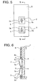
- Fig. 5 is a front view of an elevator hall button device according to Embodiment 3 of the present invention
- Fig. 6 is a sectional view taken along the line VI-VI of Fig. 5
- each of the surfaces of the button caps 5 of the upper button 2 and the lower button 3 has a button convex portion (convex character) 5b provided on the each of the surfaces for tactually telling an elevator user whether a button which the elevator user touches is the upper button 2 or the lower button 3.
- a front shape of the button convex portion 5b is a shape of an arrow pointing to a corresponding direction.
- This embodiment is the same as Embodiment 1 in other constructions.
- the button convex portion 5b is provided on the surface of the button cap 5.
- the shape of the button convex portion 5b is the arrow shape, but it is not limited thereto.
- the shape of the button convex portion 5b may be a triangle, characters such as "up” and “down”, or the like. Further, it is also possible to provide the button convex portion on the surfaces of the button caps 13, 14 as described in Embodiment 2.
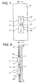
- Fig. 7 is a front view of an elevator hall button device according to Embodiment 4 of the present invention
- Fig. 8 is a sectional view taken along the line VIII-VIII of Fig. 7
- first and second floor number convex portions 15, 16 for tactually telling the elevator user an own floor number.
- the first floor number convex portion 15 is a protrusion formed in a shape of a number indicating a floor number.
- the second floor number convex portion 16 is Braille.
- This embodiment is the same as Embodiment 1 in other constructions.
- the floor number convex portion is not limited to the number-shaped protrusion and the Braille. Further, the floor number convex protrusion may be provided on the hall button devices according to Embodiment 2 and Embodiment 3.
Landscapes
- Engineering & Computer Science (AREA)
- Automation & Control Theory (AREA)
- Mechanical Engineering (AREA)
- Computer Networks & Wireless Communication (AREA)
- Elevator Control (AREA)
- Indicating And Signalling Devices For Elevators (AREA)
Claims (4)
- Stockwerksknopfeinrichtung für einen Aufzug mit:einem oberen Knopf (2); und einem unteren Knopf (3), wobei der obere Knopf (2) und der untere Knopf (3) an einer Stockwerkswand vorgesehen sind und vertikal zueinander ausgerichtet sind, und jeweils einen Knopfbetätigungsabschnitt (5), der durch einen Aufzugnutzer betätigt wird, aufweisen,dadurch gekennzeichnet, dass:der Knopfbetätigungsabschnitt (5) ein erstes Ende, das ein vertikales Ende des Knopfbetätigungsabschnittes (5) ist und ein zweites Ende, das ein anderes vertikales Ende des Knopfbetätigungsabschnittes (5) ist, aufweist;eine Fläche des Knopfbetätigungsabschnittes (5) eine solche Querschnittsfläche aufweist, dass sie von dem zweiten Ende zu dem ersten Ende hin allmählich in einer abgerundeten Form ansteigt; undder Knopfbetätigungsabschnitt (5) des oberen Knopfs (2) und der Knopfbetätigungsabschnitt (5) des unteren Knopfs (3) angeordnet sind, dass sie zueinander vertikal entgegengesetzt ausgerichtet sind.
- Stockwerksknopfeinrichtung für einen Aufzug mit: einem oberen Knopf (11) und einem unteren Knopf (12), wobei der obere Knopf (11) und der untere Knopf (12) an einer Stockwerkswand vorgesehen sind und vertikal zueinander ausgerichtet sind und jeweils einen Knopfbetätigungsabschnitt (13, 14), der durch einen Aufzugsnutzer betätigt wird, aufweisen, wobei
eine Fläche zumindest einer der Knopfbetätigungsabschnitte (13, 14) des oberen Knopfes (11) und des unteren Knopfes (12) eine konvex gekrümmte Fläche ist, und
eine Fläche des anderen Knopfbetätigungsabschnittes (13, 14) des oberen Knopfes (11) und des unteren Knopfes (12) eine konkav gekrümmte Fläche ist, ferner aufweisend eine Frontplatte (8) zum Abdecken eines umgebenden Bereichs des oberen Knopfs (2, 11) und des unteren Knopfs (3, 12),
dadurch gekennzeichnet, dass ein Abschnitt an der Frontplatte (8) zwischen dem oberen Knopf (2, 11) und dem unteren Knopf (3, 12) konvexe Stockwerksnummernabschnitte aufweist, um dem Aufzugsnutzer eine Stockwerksnummer (15, 16) durch Fühlen mitzuteilen. - Stockwerksknopfeinrichtung für einen Aufzug gemäß Anspruch 1 oder 2, dadurch gekennzeichnet, dass die Fläche des Knopfbetätigungsabschnittes (5, 13, 14) jedes oberen Knopfes (2, 11) und jedes unteren Knopfes (3, 12) einen konvexen Abschnitt eines Knopfes (5b) aufweist, der den Aufzugsnutzer durch Fühlen mitteilt, ob ein berührter Knopf, der obere Knopf (2, 11) oder der untere Knopf (3, 12) ist.
- Stockwerksknopfeinrichtung für einen Aufzug gemäß Anspruch 1,
ferner mit einer Frontplatte (8) zum Abdecken eines umgebenden Bereichs des oberen Knopfes (2, 11) und des unteren Knopfes (3, 12),
dadurch gekennzeichnet, dass ein Abschnitt auf der Frontplatte (8) zwischen dem oberen Knopf (2, 11) und dem unteren Knopf (3, 12) konvexe Stockwerksnummernabschnitte aufweist, um dem Aufzugsnutzer eine Stockwerksnummer (15, 16) durch Fühlen mitzuteilen.
Applications Claiming Priority (1)
| Application Number | Priority Date | Filing Date | Title |
|---|---|---|---|
| PCT/JP2004/017713 WO2006057057A1 (ja) | 2004-11-29 | 2004-11-29 | エレベータの乗場ボタン装置 |
Publications (3)
| Publication Number | Publication Date |
|---|---|
| EP1818302A1 EP1818302A1 (de) | 2007-08-15 |
| EP1818302A4 EP1818302A4 (de) | 2012-05-09 |
| EP1818302B1 true EP1818302B1 (de) | 2013-08-14 |
Family
ID=36497806
Family Applications (1)
| Application Number | Title | Priority Date | Filing Date |
|---|---|---|---|
| EP04822429.9A Expired - Lifetime EP1818302B1 (de) | 2004-11-29 | 2004-11-29 | Stockwerksknopfvorrichtung für aufzug |
Country Status (4)
| Country | Link |
|---|---|
| EP (1) | EP1818302B1 (de) |
| JP (1) | JP4855266B2 (de) |
| CN (1) | CN1906108A (de) |
| WO (1) | WO2006057057A1 (de) |
Families Citing this family (3)
| Publication number | Priority date | Publication date | Assignee | Title |
|---|---|---|---|---|
| JP5520068B2 (ja) * | 2010-02-03 | 2014-06-11 | 三菱電機ビルテクノサービス株式会社 | エレベータの乗場ボタン装置 |
| CN106144812A (zh) * | 2016-08-08 | 2016-11-23 | 上海贝思特电气有限公司 | 一种键盘装置及其电梯键盘 |
| JP7549812B1 (ja) | 2023-03-10 | 2024-09-12 | フジテック株式会社 | エレベータ |
Family Cites Families (7)
| Publication number | Priority date | Publication date | Assignee | Title |
|---|---|---|---|---|
| JPS5368069U (de) * | 1976-11-12 | 1978-06-08 | ||
| JPS5368069A (en) * | 1976-11-30 | 1978-06-17 | Toshiba Corp | Manufacture of crystal |
| JP3628358B2 (ja) * | 1994-05-09 | 2005-03-09 | 株式会社ソニー・コンピュータエンタテインメント | ゲーム機用コントローラ |
| JPH0873145A (ja) | 1994-09-06 | 1996-03-19 | Toshiba Corp | エレベータのかご操作盤 |
| JP2000226162A (ja) * | 1999-02-04 | 2000-08-15 | Hitachi Ltd | エレベータ呼出し操作装置及びこれを備えたエレベータシステム |
| JP4010147B2 (ja) * | 2002-01-07 | 2007-11-21 | フジテック株式会社 | 操作ボタン |
| JP2004115151A (ja) * | 2002-09-24 | 2004-04-15 | Toshiba Elevator Co Ltd | エレベータの呼び操作盤 |
-
2004
- 2004-11-29 CN CNA2004800406344A patent/CN1906108A/zh active Pending
- 2004-11-29 WO PCT/JP2004/017713 patent/WO2006057057A1/ja not_active Ceased
- 2004-11-29 EP EP04822429.9A patent/EP1818302B1/de not_active Expired - Lifetime
- 2004-11-29 JP JP2006546518A patent/JP4855266B2/ja not_active Expired - Fee Related
Also Published As
| Publication number | Publication date |
|---|---|
| JP4855266B2 (ja) | 2012-01-18 |
| CN1906108A (zh) | 2007-01-31 |
| EP1818302A4 (de) | 2012-05-09 |
| EP1818302A1 (de) | 2007-08-15 |
| JPWO2006057057A1 (ja) | 2008-06-05 |
| WO2006057057A1 (ja) | 2006-06-01 |
Similar Documents
| Publication | Publication Date | Title |
|---|---|---|
| EP2159183B1 (de) | Aufzugzieletagenregistrierungsvorrichtung | |
| US6502668B1 (en) | Touch panel with click button for elevator | |
| KR100435988B1 (ko) | 엘리베이터의 표시조작장치 | |
| JP7105511B2 (ja) | トイレ用自動ドアシステム | |
| JP2011063366A (ja) | 呼び登録案内装置 | |
| JP5837782B2 (ja) | エレベータの操作パネル装置 | |
| EP1818302A1 (de) | Stockwerksknopfvorrichtung für aufzug | |
| CN108792862B (zh) | 电梯操作盘以及去往层登记方法 | |
| EP4238918B1 (de) | Aufzugssystem und aufzugssteuerungsverfahren | |
| CN105128759B (zh) | 门窗开闭开关组件 | |
| CN101010248A (zh) | 电梯用显示装置 | |
| EP3401257A1 (de) | Kabinentableau für eine aufzugskabine mit mindestens zwei kabinentüren | |
| CN109835784A (zh) | 电梯系统 | |
| JP2003204583A (ja) | ナビゲーション用リモコン | |
| JP2003186408A (ja) | 凸文字を備えた文字表示板及びその操作盤 | |
| KR20060121958A (ko) | 엘리베이터의 승강장 버튼 장치 | |
| JP2007314300A (ja) | エレベータの操作盤 | |
| JP4123222B2 (ja) | エレベーター用操作盤 | |
| JP2000226162A (ja) | エレベータ呼出し操作装置及びこれを備えたエレベータシステム | |
| JP5487130B2 (ja) | エレベータ用ボタンスイッチ及びエレベータ装置 | |
| JP6342075B2 (ja) | エレベータの操作盤 | |
| JP2003012248A (ja) | エレベータの操作盤 | |
| JP7549812B1 (ja) | エレベータ | |
| JP7209038B2 (ja) | エレベータ操作盤用センサ | |
| JP2005082299A (ja) | エレベーターの操作盤 |
Legal Events
| Date | Code | Title | Description |
|---|---|---|---|
| PUAI | Public reference made under article 153(3) epc to a published international application that has entered the european phase |
Free format text: ORIGINAL CODE: 0009012 |
|
| 17P | Request for examination filed |
Effective date: 20060727 |
|
| AK | Designated contracting states |
Kind code of ref document: A1 Designated state(s): NL |
|
| DAX | Request for extension of the european patent (deleted) | ||
| RBV | Designated contracting states (corrected) |
Designated state(s): NL |
|
| A4 | Supplementary search report drawn up and despatched |
Effective date: 20120412 |
|
| RIC1 | Information provided on ipc code assigned before grant |
Ipc: B66B 1/46 20060101AFI20120404BHEP |
|
| 17Q | First examination report despatched |
Effective date: 20120620 |
|
| GRAP | Despatch of communication of intention to grant a patent |
Free format text: ORIGINAL CODE: EPIDOSNIGR1 |
|
| GRAS | Grant fee paid |
Free format text: ORIGINAL CODE: EPIDOSNIGR3 |
|
| GRAA | (expected) grant |
Free format text: ORIGINAL CODE: 0009210 |
|
| AK | Designated contracting states |
Kind code of ref document: B1 Designated state(s): NL |
|
| REG | Reference to a national code |
Ref country code: NL Ref legal event code: T3 |
|
| PGFP | Annual fee paid to national office [announced via postgrant information from national office to epo] |
Ref country code: NL Payment date: 20131106 Year of fee payment: 10 |
|
| PLBE | No opposition filed within time limit |
Free format text: ORIGINAL CODE: 0009261 |
|
| STAA | Information on the status of an ep patent application or granted ep patent |
Free format text: STATUS: NO OPPOSITION FILED WITHIN TIME LIMIT |
|
| 26N | No opposition filed |
Effective date: 20140515 |
|
| REG | Reference to a national code |
Ref country code: NL Ref legal event code: V1 Effective date: 20150601 |
|
| PG25 | Lapsed in a contracting state [announced via postgrant information from national office to epo] |
Ref country code: NL Free format text: LAPSE BECAUSE OF NON-PAYMENT OF DUE FEES Effective date: 20150601 |