EP1818444A1 - Verfahren und Vorrichtung zum Feststellen einer Beschädigung an einem Seil - Google Patents
Verfahren und Vorrichtung zum Feststellen einer Beschädigung an einem Seil Download PDFInfo
- Publication number
- EP1818444A1 EP1818444A1 EP07007092A EP07007092A EP1818444A1 EP 1818444 A1 EP1818444 A1 EP 1818444A1 EP 07007092 A EP07007092 A EP 07007092A EP 07007092 A EP07007092 A EP 07007092A EP 1818444 A1 EP1818444 A1 EP 1818444A1
- Authority
- EP
- European Patent Office
- Prior art keywords
- wires
- rope
- bundle
- predetermined
- metallic
- Prior art date
- Legal status (The legal status is an assumption and is not a legal conclusion. Google has not performed a legal analysis and makes no representation as to the accuracy of the status listed.)
- Withdrawn
Links
- 238000000034 method Methods 0.000 title claims abstract description 11
- 230000004907 flux Effects 0.000 claims abstract description 25
- 238000000576 coating method Methods 0.000 description 14
- 239000011248 coating agent Substances 0.000 description 13
- 238000005452 bending Methods 0.000 description 8
- 230000003247 decreasing effect Effects 0.000 description 7
- 230000007423 decrease Effects 0.000 description 5
- 229920000049 Carbon (fiber) Polymers 0.000 description 4
- 239000004917 carbon fiber Substances 0.000 description 4
- VNWKTOKETHGBQD-UHFFFAOYSA-N methane Chemical compound C VNWKTOKETHGBQD-UHFFFAOYSA-N 0.000 description 4
- 239000011368 organic material Substances 0.000 description 4
- 229920003002 synthetic resin Polymers 0.000 description 4
- 239000000057 synthetic resin Substances 0.000 description 4
- 230000006866 deterioration Effects 0.000 description 3
- 238000003825 pressing Methods 0.000 description 3
- 229920005989 resin Polymers 0.000 description 3
- 239000011347 resin Substances 0.000 description 3
- 229920006231 aramid fiber Polymers 0.000 description 2
- 238000010586 diagram Methods 0.000 description 2
- 230000000694 effects Effects 0.000 description 2
- 239000013307 optical fiber Substances 0.000 description 2
- 230000008569 process Effects 0.000 description 2
- 230000005476 size effect Effects 0.000 description 2
- 241001274660 Modulus Species 0.000 description 1
- 239000000853 adhesive Substances 0.000 description 1
- 230000001070 adhesive effect Effects 0.000 description 1
- 238000006056 electrooxidation reaction Methods 0.000 description 1
- 230000007774 longterm Effects 0.000 description 1
- 230000005389 magnetism Effects 0.000 description 1
- 238000004519 manufacturing process Methods 0.000 description 1
- 239000000463 material Substances 0.000 description 1
- 238000012986 modification Methods 0.000 description 1
- 230000004048 modification Effects 0.000 description 1
- 238000012544 monitoring process Methods 0.000 description 1
- 230000003287 optical effect Effects 0.000 description 1
- 230000007704 transition Effects 0.000 description 1
Images


Classifications
-
- D—TEXTILES; PAPER
- D07—ROPES; CABLES OTHER THAN ELECTRIC
- D07B—ROPES OR CABLES IN GENERAL
- D07B1/00—Constructional features of ropes or cables
- D07B1/16—Ropes or cables with an enveloping sheathing or inlays of rubber or plastics
- D07B1/165—Ropes or cables with an enveloping sheathing or inlays of rubber or plastics characterised by a plastic or rubber inlay
-
- B—PERFORMING OPERATIONS; TRANSPORTING
- B66—HOISTING; LIFTING; HAULING
- B66B—ELEVATORS; ESCALATORS OR MOVING WALKWAYS
- B66B7/00—Other common features of elevators
- B66B7/06—Arrangements of ropes or cables
-
- D—TEXTILES; PAPER
- D07—ROPES; CABLES OTHER THAN ELECTRIC
- D07B—ROPES OR CABLES IN GENERAL
- D07B1/00—Constructional features of ropes or cables
- D07B1/06—Ropes or cables built-up from metal wires, e.g. of section wires around a hemp core
- D07B1/0673—Ropes or cables built-up from metal wires, e.g. of section wires around a hemp core having a rope configuration
-
- D—TEXTILES; PAPER
- D07—ROPES; CABLES OTHER THAN ELECTRIC
- D07B—ROPES OR CABLES IN GENERAL
- D07B1/00—Constructional features of ropes or cables
- D07B1/14—Ropes or cables with incorporated auxiliary elements, e.g. for marking, extending throughout the length of the rope or cable
-
- D—TEXTILES; PAPER
- D07—ROPES; CABLES OTHER THAN ELECTRIC
- D07B—ROPES OR CABLES IN GENERAL
- D07B1/00—Constructional features of ropes or cables
- D07B1/14—Ropes or cables with incorporated auxiliary elements, e.g. for marking, extending throughout the length of the rope or cable
- D07B1/145—Ropes or cables with incorporated auxiliary elements, e.g. for marking, extending throughout the length of the rope or cable comprising elements for indicating or detecting the rope or cable status
-
- D—TEXTILES; PAPER
- D07—ROPES; CABLES OTHER THAN ELECTRIC
- D07B—ROPES OR CABLES IN GENERAL
- D07B1/00—Constructional features of ropes or cables
- D07B1/16—Ropes or cables with an enveloping sheathing or inlays of rubber or plastics
- D07B1/162—Ropes or cables with an enveloping sheathing or inlays of rubber or plastics characterised by a plastic or rubber enveloping sheathing
-
- D—TEXTILES; PAPER
- D07—ROPES; CABLES OTHER THAN ELECTRIC
- D07B—ROPES OR CABLES IN GENERAL
- D07B1/00—Constructional features of ropes or cables
- D07B1/24—Ropes or cables with a prematurely failing element
-
- D—TEXTILES; PAPER
- D07—ROPES; CABLES OTHER THAN ELECTRIC
- D07B—ROPES OR CABLES IN GENERAL
- D07B2201/00—Ropes or cables
- D07B2201/10—Rope or cable structures
- D07B2201/1012—Rope or cable structures characterised by their internal structure
-
- D—TEXTILES; PAPER
- D07—ROPES; CABLES OTHER THAN ELECTRIC
- D07B—ROPES OR CABLES IN GENERAL
- D07B2201/00—Ropes or cables
- D07B2201/10—Rope or cable structures
- D07B2201/1012—Rope or cable structures characterised by their internal structure
- D07B2201/102—Rope or cable structures characterised by their internal structure including a core
-
- D—TEXTILES; PAPER
- D07—ROPES; CABLES OTHER THAN ELECTRIC
- D07B—ROPES OR CABLES IN GENERAL
- D07B2201/00—Ropes or cables
- D07B2201/10—Rope or cable structures
- D07B2201/1028—Rope or cable structures characterised by the number of strands
- D07B2201/1036—Rope or cable structures characterised by the number of strands nine or more strands respectively forming multiple layers
-
- D—TEXTILES; PAPER
- D07—ROPES; CABLES OTHER THAN ELECTRIC
- D07B—ROPES OR CABLES IN GENERAL
- D07B2201/00—Ropes or cables
- D07B2201/10—Rope or cable structures
- D07B2201/104—Rope or cable structures twisted
-
- D—TEXTILES; PAPER
- D07—ROPES; CABLES OTHER THAN ELECTRIC
- D07B—ROPES OR CABLES IN GENERAL
- D07B2201/00—Ropes or cables
- D07B2201/20—Rope or cable components
- D07B2201/2001—Wires or filaments
- D07B2201/2009—Wires or filaments characterised by the materials used
-
- D—TEXTILES; PAPER
- D07—ROPES; CABLES OTHER THAN ELECTRIC
- D07B—ROPES OR CABLES IN GENERAL
- D07B2201/00—Ropes or cables
- D07B2201/20—Rope or cable components
- D07B2201/2015—Strands
- D07B2201/2038—Strands characterised by the number of wires or filaments
- D07B2201/204—Strands characterised by the number of wires or filaments nine or more wires or filaments respectively forming multiple layers
-
- D—TEXTILES; PAPER
- D07—ROPES; CABLES OTHER THAN ELECTRIC
- D07B—ROPES OR CABLES IN GENERAL
- D07B2201/00—Ropes or cables
- D07B2201/20—Rope or cable components
- D07B2201/2015—Strands
- D07B2201/2042—Strands characterised by a coating
- D07B2201/2044—Strands characterised by a coating comprising polymers
-
- D—TEXTILES; PAPER
- D07—ROPES; CABLES OTHER THAN ELECTRIC
- D07B—ROPES OR CABLES IN GENERAL
- D07B2201/00—Ropes or cables
- D07B2201/20—Rope or cable components
- D07B2201/2047—Cores
- D07B2201/2052—Cores characterised by their structure
- D07B2201/2053—Cores characterised by their structure being homogeneous
-
- D—TEXTILES; PAPER
- D07—ROPES; CABLES OTHER THAN ELECTRIC
- D07B—ROPES OR CABLES IN GENERAL
- D07B2201/00—Ropes or cables
- D07B2201/20—Rope or cable components
- D07B2201/2047—Cores
- D07B2201/2052—Cores characterised by their structure
- D07B2201/2059—Cores characterised by their structure comprising wires
- D07B2201/2061—Cores characterised by their structure comprising wires resulting in a twisted structure
-
- D—TEXTILES; PAPER
- D07—ROPES; CABLES OTHER THAN ELECTRIC
- D07B—ROPES OR CABLES IN GENERAL
- D07B2201/00—Ropes or cables
- D07B2201/20—Rope or cable components
- D07B2201/2047—Cores
- D07B2201/2052—Cores characterised by their structure
- D07B2201/2065—Cores characterised by their structure comprising a coating
-
- D—TEXTILES; PAPER
- D07—ROPES; CABLES OTHER THAN ELECTRIC
- D07B—ROPES OR CABLES IN GENERAL
- D07B2205/00—Rope or cable materials
- D07B2205/30—Inorganic materials
- D07B2205/3021—Metals
-
- D—TEXTILES; PAPER
- D07—ROPES; CABLES OTHER THAN ELECTRIC
- D07B—ROPES OR CABLES IN GENERAL
- D07B2301/00—Controls
- D07B2301/55—Sensors
- D07B2301/5531—Sensors using electric means or elements
- D07B2301/555—Sensors using electric means or elements for measuring magnetic properties
-
- D—TEXTILES; PAPER
- D07—ROPES; CABLES OTHER THAN ELECTRIC
- D07B—ROPES OR CABLES IN GENERAL
- D07B2401/00—Aspects related to the problem to be solved or advantage
- D07B2401/20—Aspects related to the problem to be solved or advantage related to ropes or cables
- D07B2401/2065—Reducing wear
-
- D—TEXTILES; PAPER
- D07—ROPES; CABLES OTHER THAN ELECTRIC
- D07B—ROPES OR CABLES IN GENERAL
- D07B2501/00—Application field
- D07B2501/20—Application field related to ropes or cables
- D07B2501/2007—Elevators
Definitions
- the present invention relates to a rope usable in an apparatus for moving an object, for example, an elevator, and a method for measuring a damage of the rope.
- a prior art rope as disclosed by JP-A-2001-262482 outer peripheries of wires are respectively coated with a synthetic resin, each of bundles of the wires is twisted, the bundles of the wires are twisted to form the rope, and an outer periphery of the rope is coated with the synthetic resin.
- the rope includes an optical fiber, and a deterioration of the rope is detected from a decrease of optical conductivity of the optical fiber.
- An object of the present invention is to provide a rope in which a damage thereof is securely and easily detectable, and a method for detecting the damage of the rope securely and easily.
- a rope comprising a bundle of wires each of which is adapted to bear a tensile load to be borne by the rope
- predetermined one of the wires is configured to be at least partially breakable by applying tension and flexure to the rope, before an at least partial breakage of a rest of the wires other than the predetermined one of the wires by applying the tension and flexure to the rope so that the at least partial breakage occurs securely on the predetermined one of the wires before the at least partial breakage of the rest of the wires
- the damage of the rope is measurable by monitoring only the predetermined one of the wires so that the damage thereof is securely and easily detectable.
- the predetermined one of the wires is capable of having at least one of a maximum (highest) stress generated in the predetermined one of the wires by at least one of the tension and flexure greater than maximum (highest) stresses generated in the wires of the rest by the at least one of the tension and flexure, and a (fatigue) strength (per unit cross sectional area) of the predetermined one of the wires against stress generated in the predetermined one of the wires by the at least one of the tension and flexure lower than (fatigue) strength (per unit cross sectional areas) of the wires of the rest against stresses generated in the wires of the rest by the at least one of the tension and flexure, in such a manner that the predetermined one of the wires is capable of having the maximum stress generated in the predetermined one of the wires by at least one of the tension and flexure greater than the (fatigue) strength (per unit cross sectional area) of the predetermined one of the wires against stress generated in the predetermined one of the wires by the at least one of the
- a cross sectional area of the predetermined one of the wires is greater than cross sectional areas of the rest of the wires
- the maximum stress generated in the predetermined one of the wires by the at least one of the tension and flexure is greater than maximum stresses generated in the wires of the rest by the at least one of the tension and flexure
- the (fatigue) strength (per unit cross sectional area) against stress generated in the predetermined one of the wires by at least one of the tension and flexure is decreased by size effect in (fatigue) strength in comparison with the (fatigue) strengths (per unit cross sectional areas) against stresses generated in the wires of the rest by the at least one of the tension and flexure, so that the at least partial breakage occurs securely on the predetermined one of the wires before the at least partial breakage of the rest of the wires.
- cross sectional areas of the predetermined one of the wires and the wires of the rest are constant respectively in a longitudinally direction of the bundle of wire
- the at least partial breakage of the predetermined one of the wires on the outer periphery of the bundle of wires is securely generated by the relatively greater maximum (highest) stress of the predetermined one of the wires in comparison with the rest of the wires because the stress in the rope increases in accordance with a radial distance of a position on which the stress is generated and a radial center (radially zero position) of the rope, or if at a longitudinal position of the rope, the predetermined one of the wires is arranged at the outer periphery of the bundle of wires while at the longitudinal position of the rope, the cross sectional area of the predetermined one of the wires is greater than the cross sectional areas of the rest of the wires, the at least partial
- the predetermined one of the wires and the wires of the rest may be metallic, and the predetermined one of the wires may be magnetically permeable so that the breakage of the predetermined one of the wires can be magnetically.
- the predetermined one of the wires and the wires of the rest may be electrically conductive.
- the predetermined one of the wires may be electrically connected to the wires of the rest in such a manner that an electric potential difference between longitudinally opposite ends of the predetermined one of the wires in a longitudinal length of the rope is equal to electric potential differences between longitudinally opposite ends of the wires of the rest in the longitudinal length of the rope, so that an electrochemical corrosion on the wires is restrained.
- a main component of the predetermined one of the wires may be equal to a main component of the rest of the wires.
- the bundle of wires may be twisted.
- the bundle of wires may include a first twisted bundle of the wires and a second twisted bundle of the wires, and the second twisted bundle extends helically around the first twisted bundle of the wires to surround the first twisted bundle of the wires. It is preferable for positioning the predetermined one of the wires to securely and easily detect the at least partial breakage thereof that the predetermined one of the wires is included by the second twisted bundle of the wires.
- the rope may further comprises a synthetic resin cover surrounding the second twisted bundle.
- the predetermined at least two of the wires configured to be at least partially breakable by applying at least one of the tension and flexure to the rope before the at least partial breakage of the rest of the wires, if the predetermined at least two of the wires contact at least partially each other in a direction perpendicular to longitudinal directions of the wires while at least one of the wires of the rest is prevented from interrupting at least partially the at least partial contact between the predetermined at least two of the wires, a transition of the at least partial breakage between the predetermined at least two of the wires is maintained to securely and easily detect the at least partial breakage of the predetermined at least two of the wires.
- a method for detecting a damage of the above rope comprises the steps of : generating a magnetic field in the bundle of wires, and measuring a leakage of a magnetic flux from the bundle of wires so that a damage of rope corresponding to a degree of the leakage of the magnetic flux is detected, the damage of rope can be detected in non-contact with respect to the rope even when the rope is running. It is preferable in this case that the magnetic flux extends longitudinally in the bundle of wires.
- an apparatus for detecting a damage of the above rope comprises, a pair of magnetic cores magnetizable to generate a magnetic field in the bundle of wires, and a magnetic sensor for measuring a leakage of a magnetic flux from the bundle of wires so that a damage of rope corresponding to a degree of the leakage of the magnetic flux is detected, the damage of rope can be detected in non-contact between the rope and each of the pair of magnetic core and the magnetic sensor even when the rope is running.
- the magnetic cores are spaced apart from each other in a longitudinal direction of the bundle of wires to generate the magnetic flux extending longitudinally,in the bundle of wires, and the magnetic sensor is measurable the leakage of the magnetic flux at a position between the magnetic cores in the longitudinal direction.
- pulleys 5a and 5b for receiving a rope 10 are mounted on a lower part of a car 1 for carrying a passenger(s) or load, and a pulley 5e for receiving the rope is arranged above a counterweight 2 counterpoising the car 1 when about a half of a safe working load is borne by the car 1.
- Pulleys 5c and 5d for receiving the rope 10 are arranged at a top of a hoistway 7, and a driving device 3 including a sheave 3a is arranged at a lower part of the hoistway 7.
- the rope 10 of the invention extends from a rope holder 6a arranged at the top of the hoistway 7, onto the pulleys 5a and 5b on the lower part of the car 1 and the pulley 5c on the top of the hoistway 7 so that the rope 10 is wrapped around the sheave 3a of the driving device 3.
- the rope 10 further extends on the pulley 5d at the top of the hoistway 7 and the pulley 5e of the counterweight 2, and terminates at a rope holder 6b at the top of the hoistway 7.
- the rope 10 is bendy, and has a great friction-coefficient between the sheave 3a and a coating of the rope, so that the rope 10 has a longer operating life and can transmit securely a driving force even when a diameter of the sheave is small.
- the diameter of the sheave may be from one third to a half in comparison with the prior art sheave. Therefore, a driving torque of the driving device may be from one third to a half in comparison with the prior art driving device so that the driving device can be significantly downsized.
- diameters of the pulleys at the lower part of the car 1, above the counterweight 2 and the top of the hoistway 7 are decreased similarly so that an overhead (a distance between the highest floor and a ceiling of the hoistway) and a pit depth (a distance between the lowest floor and a pit of the hoistway) can be decreased.
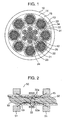
- a synthetic resin coating 15 is formed on an outside of a first structure 12 arranged at a central portion of the rope 10 and second structures 13 arranged around the first structure 12.
- the first structure 12 is formed by, for example, twisting strands 22 around a core 23 to form an inner structure 24, each of which strands is formed by twisting metallic wires 21 substantially parallel to each other, and forming an organic material coating 25 on an outer periphery of the inner structure 24.
- the core 23 may be formed of single organic material (resin), a rope of organic material (resin) or a strand which is formed by twisting metallic wires. For obtaining a longer operating life, the core 23 formed of resin is preferable. Clearances are formed between the strands 22 adjacent to each other to be filled with the coating 25.
- Each of the second structure 13 is formed by twisting metallic wires 31 and 32 substantially parallel to each other to form an outer structure 33, and forming an organic material coating 34 on an outer periphery of the outer structure 33.
- the metallic wires 32 are arranged at an outer periphery of the outer structure 33. In this case, diameters of the metallic wires 32 are greater than those of the metallic wires 21 and 31 or a strength of each of the metallic wires 32 is smaller than that of the metallic wires 21 and 31.
- a pressing force is generated between the first structure 12 and each of the second structures 13 twisted around the first structure 12 by a tension applied to the rope 10, and a radial pressing force is also generated therebetween by pressing the rope against the pulleys and sheave. Flexures of the rope are generated at every passes of the rope on the pulleys and sheave. In this actual operating condition, compressive pressures are generated between the first structure 12 and each of the second structures 13 and between the metallic wires 21, 31, 32, and a flexural stress in each of the metallic wires and mutual slip between the metallic wires are generated. Therefore, the metallic wires are at least partially broken by stress variation and slip under the compressive pressures causing a fretting.
- a stress generated in the metallic wire by the flexures of the rope increases in accordance with an increase of radial distance of a position of the metallic wire from a radial center of the rope and an increase of diameter of the metallic wire. Further, a slip on the metallic wire increases in accordance with the increase of radial distance of the position of the metallic wire from the radial center of the rope. That is, the radially outermost metallic wire bears the most severe condition.
- a coating 25 is inserted between the strands 22 of the first structure, and a coating 34 and the coating 25 are inserted between the second structures 13, so that a direct contact between the metallic wires arranged between the strands 22 and between the first and second structures 12 and 13 is prevented.
- the metallic wires 21 substantially parallel to each other contact directly each other in the strands 22, and the metallic wires 31 and 32 substantially parallel to each other contact directly each other in the second structures 13. That is, in taking a broad view, not point contacts but line contacts are formed between the metallic wires. Therefore, pressures generated between surfaces of the metallic wires by the tension applied to the rope is decreased to restrain a decrease of the operating life caused by the fretting.
- the metallic wires are at least partially broken by repeated flexures of the rope during a long operating time period.
- the metallic wires 32 arranged on the outer periphery of the rope have greater diameters or lower strengths in comparison with those of the metallic wires 21 and 31, the metallic wires 32 arranged on the outer periphery of the rope are at least partially broken prior to the metallic wires 21 and 31 irrespective of data spread in material strength and production.
- the metallic wires 32 are significantly differentiated from the metallic wires 21 and 31 in diameter or strength irrespective of various conditions.
- Fig. 2 is a cross sectional view showing a principle of detecting the breakage of the metallic wires 32.
- the coatings 15 and 34 of the rope are imaginarily removed to expose the metallic wires 32.
- a breakage detector 50 includes two magnetic exiters 51 arranged along the rope and a magnetic device 52 for detecting a leakage magnetic flux from the rope. By energizing the exiters 51, a magnetism generated between the exiters 51 flows into the metallic wires 32 through the coating of the rope to generate a magnetic flux 53.
- a magnetoresistance is constant in the rope so that the magnetic flux flows from one of the exiters 51 to the other of the exiters 51.
- the magnetoresistance increases at the breakage portion 32a so that a magnetic flux 531 flows out of the rope.
- An amount of the leakage magnetic flux 531 out of the rope is in proportion to a degree of the magnetoresistance, that is, a number of the broken metallic wires 32.
- the magnetic flux passes the metallic wires arranged on an outside of the breakage of the metallic wires so that the amount of the leakage magnetic flux out of the rope is decreased. Therefore, it is difficult to detect the breakage with the magnetic device 52.
- the breakage of the metallic wires starts after a long term of use, the breakage occurs on the metallic wires 32 on the outer periphery of the rope, so that the breakage of the metallic wires on the outer periphery of the rope is detectable magnetically. Further, the number of the broken metallic wires is measurable from the amount of the leakage magnetic flux. The residual strength of the rope and a future variation of the residual strength of the rope can be estimated on recorded data of the number of the broken metallic wires and the residual strength of the rope, so that a rope exchange timing can be easily determined.
- Fig. 3 is a diagram showing a relationship between a number of bending times and a rope strength, and the rope strength decreases gradually in accordance with an increase of the number of bending times during the use of the rope.
- Fig. 4 shows a flow chart of these operation, and data of the relationship of Fig. 3 and frequency of use are recorded. From the above data and the number of the broken metallic wires detected by the deterioration measuring method as shown in Fig. 2, the residual strength of the rope is measured. On the other hand, when the breakage of the metallic wires has been started, a number of bending times in which the rope is safely usable continuously in future is determined on the number of the broken metallic wires, and the acceptable number of bending times is converted with the frequency of use to a number of days, so that the strength of the rope, the time period in which the rope is usable in future, a rope exchange timing and so forth are output.
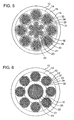
- Fig. 5 is a cross sectional view of the rope as another embodiment of the invention, and reference numerals commonly used between Figs. 1 and 5 denote common elements respectively.
- a difference between Figs. 1 and 5 is that the number of the metallic wires 32 breakable prior to the metallic wires 21 and 31 is decreased.
- the other structure is common with Fig. 1, whereby a detailed explanation is not done. In this case, a rate of [strength/cross sectional area] is increased.
- the number of the metallic wires 32 breakable in advance is decreased and an accuracy in data as shown in Fig. 3 is required, however, the same effect is obtainable.
- Fig. 6 is a cross sectional view of the rope as another embodiment of the invention, and reference numerals commonly used between Figs. 1 and 6 denote common elements respectively.
- a difference between Figs. 1 and 6 is that the first structure 12 as the core includes the strands 22 in each of which the metallic wires 21 are twisted around the core 23, and the coating 25, and that the coating is deleted from the second structure 13.
- the other structure is common with Fig. 1, whereby a detailed explanation is not done.
- the metallic wires 21 in the first structure 12 can contact each other in parallel so that the life time of the rope is extensible. Further, since the second structure 13 does not need to be coated, a producing process can be cut down.
- the coating 15 is inserted between the strands adjacent to each other.
- the coating 15 and the inner structure 33 need to be adhered to each other by an adhesive.
- the metallic wires 32 as the object of the invention are breakable prior to the other metallic wires 21 and 31 to detect the deterioration of the rope, so that the same effect is obtainable.
- the metallic wires 32 breakable in advance are arrange on the outer periphery of the second structure in the above embodiments, the metallic wires breakable in advance may be arranged in a part of the metallic wires 21 of the first structure 12 or a part of the metallic wires 31 in the second structure 13 so that the purpose is achieved.
Landscapes
- Ropes Or Cables (AREA)
- Lift-Guide Devices, And Elevator Ropes And Cables (AREA)
- Maintenance And Inspection Apparatuses For Elevators (AREA)
- Investigating Strength Of Materials By Application Of Mechanical Stress (AREA)
Applications Claiming Priority (2)
| Application Number | Priority Date | Filing Date | Title |
|---|---|---|---|
| JP2003007354A JP4310112B2 (ja) | 2003-01-15 | 2003-01-15 | ロープ及びロープの劣化診断方法 |
| EP03029800A EP1439262B1 (de) | 2003-01-15 | 2003-12-23 | Seil |
Related Parent Applications (1)
| Application Number | Title | Priority Date | Filing Date |
|---|---|---|---|
| EP03029800A Division EP1439262B1 (de) | 2003-01-15 | 2003-12-23 | Seil |
Publications (1)
| Publication Number | Publication Date |
|---|---|
| EP1818444A1 true EP1818444A1 (de) | 2007-08-15 |
Family
ID=32588512
Family Applications (2)
| Application Number | Title | Priority Date | Filing Date |
|---|---|---|---|
| EP07007092A Withdrawn EP1818444A1 (de) | 2003-01-15 | 2003-12-23 | Verfahren und Vorrichtung zum Feststellen einer Beschädigung an einem Seil |
| EP03029800A Expired - Lifetime EP1439262B1 (de) | 2003-01-15 | 2003-12-23 | Seil |
Family Applications After (1)
| Application Number | Title | Priority Date | Filing Date |
|---|---|---|---|
| EP03029800A Expired - Lifetime EP1439262B1 (de) | 2003-01-15 | 2003-12-23 | Seil |
Country Status (6)
| Country | Link |
|---|---|
| EP (2) | EP1818444A1 (de) |
| JP (1) | JP4310112B2 (de) |
| KR (1) | KR101120703B1 (de) |
| CN (1) | CN100412266C (de) |
| DE (1) | DE60327414D1 (de) |
| TW (1) | TWI251634B (de) |
Cited By (3)
| Publication number | Priority date | Publication date | Assignee | Title |
|---|---|---|---|---|
| WO2010072549A1 (de) * | 2008-12-22 | 2010-07-01 | Inventio Ag | Verfahren zur überwachung eines aufzugstragmittels, eine aufzugstragmittel-überwachungseinrichtung und eine aufzugsanlage mit einer derartigen überwachungseinrichtung |
| WO2010085078A3 (ko) * | 2009-01-20 | 2010-11-04 | 유근임 | 라운드슬링 및 그 제조방법 |
| WO2011004071A3 (en) * | 2009-07-08 | 2011-09-01 | Kone Corporation | Rope of a hoisting apparatus, rope arrangement, elevator and method |
Families Citing this family (21)
| Publication number | Priority date | Publication date | Assignee | Title |
|---|---|---|---|---|
| JP4523364B2 (ja) * | 2004-08-31 | 2010-08-11 | 株式会社日立製作所 | エレベータ |
| GB0428138D0 (en) | 2004-12-23 | 2005-01-26 | Aea Technology Plc | Detecting failures in flexible multistrand steel structures |
| JP4825525B2 (ja) * | 2006-02-01 | 2011-11-30 | 株式会社日立ビルシステム | ワイヤロープの探傷装置 |
| JP4386371B2 (ja) * | 2006-02-10 | 2009-12-16 | 株式会社日立製作所 | エレベータ装置 |
| SG143143A1 (en) * | 2006-12-04 | 2008-06-27 | Inventio Ag | Synthetic fiber rope |
| JP2010254394A (ja) * | 2009-04-22 | 2010-11-11 | Mitsubishi Electric Building Techno Service Co Ltd | ワイヤロープおよびそのワイヤロープの寿命を点検する方法 |
| TWI401371B (zh) * | 2010-05-03 | 2013-07-11 | Automotive Res & Testing Ct | A brake actuator with a cable force measuring device |
| WO2011158871A1 (ja) * | 2010-06-16 | 2011-12-22 | Natac株式会社 | エレベータ用ワイヤロープの損傷監視方法及びエレベータ用ワイヤロープの損傷監視装置 |
| DE202010013519U1 (de) * | 2010-09-23 | 2010-11-25 | Barthels-Feldhoff Gmbh & Co. Kg | Seil |
| EP2634130A1 (de) * | 2010-10-27 | 2013-09-04 | Mitsubishi Electric Corporation | Seil für einen aufzug |
| JP2013142202A (ja) * | 2012-01-06 | 2013-07-22 | Endo Kogyo Kk | ワイヤロープ及びスプリングバランサー |
| CN105984773B (zh) * | 2015-02-28 | 2020-06-12 | 通力股份公司 | 用于检测多个电梯绳索的总载荷的绳索载荷检测装置 |
| US11427959B2 (en) | 2015-12-21 | 2022-08-30 | Nippon Sheet Glass Company, Limited | Rubber-reinforcing cord and rubber product using same |
| AT518541B1 (de) * | 2016-05-09 | 2017-11-15 | Teufelberger Seil Ges M B H | Stahlseil |
| CN106480759B (zh) * | 2016-09-23 | 2019-05-07 | 成都九十度工业产品设计有限公司 | 一种建筑用缆绳保护器 |
| WO2019081412A1 (en) * | 2017-10-27 | 2019-05-02 | Bekaert Advanced Cords Aalter Nv | BELT COMPRISING STEEL CABLE DESIGNED FOR DETECTION OF WEAR |
| CN107738980A (zh) * | 2017-11-13 | 2018-02-27 | 佛山市领卓科技有限公司 | 一种缆绳 |
| CN111366319B (zh) * | 2020-03-24 | 2021-11-09 | 安阳工学院 | 一种基于频率法测定索结构试样损伤的装置及使用方法 |
| DE112020007544T5 (de) * | 2020-08-27 | 2023-06-15 | Mitsubishi Electric Corporation | Riemen, Verfahren zu dessen Herstellung und Aufzug |
| EP4266002A4 (de) * | 2020-12-21 | 2024-08-14 | Neubrex Co., Ltd. | Verstärktes dss-kabel |
| WO2024091125A1 (en) * | 2022-10-25 | 2024-05-02 | Wire Tech As | A strand for a wire rope and a system for detecting wear and fatigue of a wire rope |
Citations (3)
| Publication number | Priority date | Publication date | Assignee | Title |
|---|---|---|---|---|
| FR2405483A1 (fr) * | 1977-10-06 | 1979-05-04 | Plessey Handel Investment Ag | Appareil pour l'essai non-destructif d'objets ferromagnetiques allonges |
| LU85155A1 (de) * | 1983-12-21 | 1985-09-12 | Trefilarbed Drahtwerk | Verfahren zum pruefen von seilen,die aus metalldraehten bzw.metallitzen bestehen |
| GB2206969A (en) * | 1987-06-25 | 1989-01-18 | Coal Ind | Non-destructive magnetic testing device |
Family Cites Families (13)
| Publication number | Priority date | Publication date | Assignee | Title |
|---|---|---|---|---|
| US3104515A (en) * | 1962-04-09 | 1963-09-24 | United States Steel Corp | Wire rope |
| DE1270450B (de) * | 1962-06-06 | 1968-06-12 | Alfred Dietz | Drahtseil |
| BE755698A (fr) * | 1969-09-03 | 1971-02-15 | Anglo Amer Corp South Africa | Essai par courant continu de cables et cordages |
| AT341917B (de) * | 1976-04-08 | 1978-03-10 | Teufelberger Drahtseil | Drehungsarmes, mehrlagiges litzenspiralseil |
| AT381967B (de) * | 1982-04-23 | 1986-12-29 | Teufelberger Gmbh | Drahtseil |
| JPS59650A (ja) * | 1982-06-28 | 1984-01-05 | Hitachi Ltd | ワイヤ−ロ−プの電磁探傷装置 |
| CA2169431C (en) * | 1995-03-06 | 2005-07-12 | Claudio De Angelis | Equipment for recognising when synthetic fibre cables are ripe for being discarded |
| JP2920082B2 (ja) * | 1995-03-09 | 1999-07-19 | 東京製綱株式会社 | マークロープ |
| JPH1019852A (ja) * | 1996-07-03 | 1998-01-23 | Hitachi Building Syst Co Ltd | ワイヤロープ探傷装置 |
| JPH1112966A (ja) * | 1997-06-17 | 1999-01-19 | Tokyo Seiko Co Ltd | 摩耗自己検知機能付きワイヤロープ |
| IL133050A (en) * | 1998-12-07 | 2003-12-10 | Inventio Ag | Device for identification of need to replace synthetic fiber ropes |
| JP4371515B2 (ja) * | 1999-01-22 | 2009-11-25 | インベンテイオ・アクテイエンゲゼルシヤフト | 合成繊維ロープのロープシースへの損傷の検知 |
| JP4500437B2 (ja) * | 2000-12-15 | 2010-07-14 | 株式会社日立ビルシステム | ワイヤーロープの損傷検出装置 |
-
2003
- 2003-01-15 JP JP2003007354A patent/JP4310112B2/ja not_active Expired - Lifetime
- 2003-12-22 TW TW092136442A patent/TWI251634B/zh not_active IP Right Cessation
- 2003-12-23 EP EP07007092A patent/EP1818444A1/de not_active Withdrawn
- 2003-12-23 EP EP03029800A patent/EP1439262B1/de not_active Expired - Lifetime
- 2003-12-23 DE DE60327414T patent/DE60327414D1/de not_active Expired - Lifetime
-
2004
- 2004-01-12 CN CNB2004100020247A patent/CN100412266C/zh not_active Expired - Lifetime
- 2004-01-14 KR KR1020040002495A patent/KR101120703B1/ko not_active Expired - Lifetime
Patent Citations (3)
| Publication number | Priority date | Publication date | Assignee | Title |
|---|---|---|---|---|
| FR2405483A1 (fr) * | 1977-10-06 | 1979-05-04 | Plessey Handel Investment Ag | Appareil pour l'essai non-destructif d'objets ferromagnetiques allonges |
| LU85155A1 (de) * | 1983-12-21 | 1985-09-12 | Trefilarbed Drahtwerk | Verfahren zum pruefen von seilen,die aus metalldraehten bzw.metallitzen bestehen |
| GB2206969A (en) * | 1987-06-25 | 1989-01-18 | Coal Ind | Non-destructive magnetic testing device |
Cited By (9)
| Publication number | Priority date | Publication date | Assignee | Title |
|---|---|---|---|---|
| WO2010072549A1 (de) * | 2008-12-22 | 2010-07-01 | Inventio Ag | Verfahren zur überwachung eines aufzugstragmittels, eine aufzugstragmittel-überwachungseinrichtung und eine aufzugsanlage mit einer derartigen überwachungseinrichtung |
| CN102256888A (zh) * | 2008-12-22 | 2011-11-23 | 因温特奥股份公司 | 用于监控电梯承载机构的方法、电梯承载机构监控装置以及具有这种监控装置的电梯设备 |
| CN102256888B (zh) * | 2008-12-22 | 2014-02-19 | 因温特奥股份公司 | 用于监控电梯承载机构的方法、电梯承载机构监控装置以及具有这种监控装置的电梯设备 |
| US8813918B2 (en) | 2008-12-22 | 2014-08-26 | Inventio Ag | Method and device for monitoring an elevator support characterizing propery |
| AU2009331700B2 (en) * | 2008-12-22 | 2016-07-07 | Inventio Ag | Method for monitoring an elevator support means, an elevator support means monitoring device, and an elevator system having such a monitoring device |
| WO2010085078A3 (ko) * | 2009-01-20 | 2010-11-04 | 유근임 | 라운드슬링 및 그 제조방법 |
| GB2479699A (en) * | 2009-01-20 | 2011-10-19 | Geun Im Yoo | Round sling and method for manufacturing the same |
| GB2479699B (en) * | 2009-01-20 | 2014-05-14 | Geun Im Yoo | Round sling and method for manufacturing the same |
| WO2011004071A3 (en) * | 2009-07-08 | 2011-09-01 | Kone Corporation | Rope of a hoisting apparatus, rope arrangement, elevator and method |
Also Published As
| Publication number | Publication date |
|---|---|
| TW200419036A (en) | 2004-10-01 |
| JP2004218147A (ja) | 2004-08-05 |
| JP4310112B2 (ja) | 2009-08-05 |
| KR101120703B1 (ko) | 2012-03-23 |
| EP1439262A2 (de) | 2004-07-21 |
| DE60327414D1 (de) | 2009-06-10 |
| TWI251634B (en) | 2006-03-21 |
| CN1517485A (zh) | 2004-08-04 |
| CN100412266C (zh) | 2008-08-20 |
| EP1439262B1 (de) | 2009-04-29 |
| KR20040066009A (ko) | 2004-07-23 |
| EP1439262A3 (de) | 2005-07-06 |
Similar Documents
| Publication | Publication Date | Title |
|---|---|---|
| EP1439262B1 (de) | Seil | |
| CN100365196C (zh) | 具有用于局部应变指示的可探测元件的电梯索及其检查方法 | |
| JP5448374B2 (ja) | ロープ端末固定装置 | |
| CN105143082B (zh) | 电梯缆绳健康监测 | |
| CN108423503B (zh) | 方法和提升装置 | |
| CN102471025B (zh) | 接触装置 | |
| CN106477411B (zh) | 方法、设施和电梯 | |
| JP4869385B2 (ja) | ロープ式エレベーター | |
| CN100387772C (zh) | 确定具有提供局部应变指示的铁磁元件的缆绳状态的方法 | |
| EP3107855B1 (de) | Verbinder für system zur inspektion eines aufzugsspanngliedes | |
| CN108712996A (zh) | 带有多个沿着承载机构布置的传感器的用于电梯设备的承载机构 | |
| CN110002321A (zh) | 用于提升设备的绳索的状态监测的方法和装置 | |
| CN109477295B (zh) | 钢缆索 | |
| JP2010195580A (ja) | 吊支持用ロープ | |
| CN107074494A (zh) | 电梯设备 | |
| JP4202950B2 (ja) | ワイヤロープ及びこれを用いた昇降装置 | |
| CN119643033A (zh) | 一种断丝损伤位置和根数实时自监测的平行钢丝智能拉索 | |
| HK1152920A (en) | Rope end fixing device | |
| HK1077605B (en) | Method of determining the condition of rope having a ferromagnetic element providing an indication of local strain | |
| HK1151776B (en) | Rope type elevator |
Legal Events
| Date | Code | Title | Description |
|---|---|---|---|
| PUAI | Public reference made under article 153(3) epc to a published international application that has entered the european phase |
Free format text: ORIGINAL CODE: 0009012 |
|
| AC | Divisional application: reference to earlier application |
Ref document number: 1439262 Country of ref document: EP Kind code of ref document: P |
|
| AK | Designated contracting states |
Kind code of ref document: A1 Designated state(s): DE FR |
|
| 17P | Request for examination filed |
Effective date: 20080214 |
|
| AKX | Designation fees paid |
Designated state(s): DE FR |
|
| 17Q | First examination report despatched |
Effective date: 20080408 |
|
| STAA | Information on the status of an ep patent application or granted ep patent |
Free format text: STATUS: THE APPLICATION IS DEEMED TO BE WITHDRAWN |
|
| 18D | Application deemed to be withdrawn |
Effective date: 20080819 |