EP1818512A2 - Collecteur de particules pour moteur de turbine à gaz - Google Patents
Collecteur de particules pour moteur de turbine à gaz Download PDFInfo
- Publication number
- EP1818512A2 EP1818512A2 EP07250501A EP07250501A EP1818512A2 EP 1818512 A2 EP1818512 A2 EP 1818512A2 EP 07250501 A EP07250501 A EP 07250501A EP 07250501 A EP07250501 A EP 07250501A EP 1818512 A2 EP1818512 A2 EP 1818512A2
- Authority
- EP
- European Patent Office
- Prior art keywords
- collection
- gas turbine
- turbine engine
- set forth
- collection material
- Prior art date
- Legal status (The legal status is an assumption and is not a legal conclusion. Google has not performed a legal analysis and makes no representation as to the accuracy of the status listed.)
- Granted
Links
- 239000002245 particle Substances 0.000 title claims description 19
- 239000000463 material Substances 0.000 claims abstract description 45
- 238000001816 cooling Methods 0.000 claims abstract description 28
- 239000012535 impurity Substances 0.000 claims abstract description 17
- 238000011144 upstream manufacturing Methods 0.000 claims 2
- 239000004576 sand Substances 0.000 abstract description 4
- 238000002485 combustion reaction Methods 0.000 description 5
- 230000014759 maintenance of location Effects 0.000 description 2
- 241000264877 Hippospongia communis Species 0.000 description 1
- 239000012809 cooling fluid Substances 0.000 description 1
- 239000000446 fuel Substances 0.000 description 1
- 238000012986 modification Methods 0.000 description 1
- 230000004048 modification Effects 0.000 description 1
Images



Classifications
-
- F—MECHANICAL ENGINEERING; LIGHTING; HEATING; WEAPONS; BLASTING
- F01—MACHINES OR ENGINES IN GENERAL; ENGINE PLANTS IN GENERAL; STEAM ENGINES
- F01D—NON-POSITIVE DISPLACEMENT MACHINES OR ENGINES, e.g. STEAM TURBINES
- F01D25/00—Component parts, details, or accessories, not provided for in, or of interest apart from, other groups
- F01D25/32—Collecting of condensation water; Drainage ; Removing solid particles
-
- F—MECHANICAL ENGINEERING; LIGHTING; HEATING; WEAPONS; BLASTING
- F02—COMBUSTION ENGINES; HOT-GAS OR COMBUSTION-PRODUCT ENGINE PLANTS
- F02C—GAS-TURBINE PLANTS; AIR INTAKES FOR JET-PROPULSION PLANTS; CONTROLLING FUEL SUPPLY IN AIR-BREATHING JET-PROPULSION PLANTS
- F02C7/00—Features, components parts, details or accessories, not provided for in, or of interest apart form groups F02C1/00 - F02C6/00; Air intakes for jet-propulsion plants
- F02C7/04—Air intakes for gas-turbine plants or jet-propulsion plants
- F02C7/05—Air intakes for gas-turbine plants or jet-propulsion plants having provisions for obviating the penetration of damaging objects or particles
-
- F—MECHANICAL ENGINEERING; LIGHTING; HEATING; WEAPONS; BLASTING
- F05—INDEXING SCHEMES RELATING TO ENGINES OR PUMPS IN VARIOUS SUBCLASSES OF CLASSES F01-F04
- F05D—INDEXING SCHEME FOR ASPECTS RELATING TO NON-POSITIVE-DISPLACEMENT MACHINES OR ENGINES, GAS-TURBINES OR JET-PROPULSION PLANTS
- F05D2260/00—Function
- F05D2260/20—Heat transfer, e.g. cooling
-
- F—MECHANICAL ENGINEERING; LIGHTING; HEATING; WEAPONS; BLASTING
- F05—INDEXING SCHEMES RELATING TO ENGINES OR PUMPS IN VARIOUS SUBCLASSES OF CLASSES F01-F04
- F05D—INDEXING SCHEME FOR ASPECTS RELATING TO NON-POSITIVE-DISPLACEMENT MACHINES OR ENGINES, GAS-TURBINES OR JET-PROPULSION PLANTS
- F05D2260/00—Function
- F05D2260/60—Fluid transfer
- F05D2260/607—Preventing clogging or obstruction of flow paths by dirt, dust, or foreign particles
Definitions
- This application relates to the inclusion of a material into air flow streams in a gas turbine engine, wherein the material has a plurality of collection zones for collecting impurities such as dirt or sand.
- Gas turbine engines are provided with a number of functional sections, including a fan section, a compressor section, a combustion section, and a turbine section. Air and fuel are combusted in the combustion section. The products of the combustion move downstream, and pass over a series of turbine rotors, driving the rotors to provide power.
- a turbine rotor will have a plurality of turbine blades that are driven by high temperature products of combustion to rotate and create the power. Cooling fluid, and typically air, is passed within a body of the turbine blades, seals, and vanes to cool the components.
- the air passing through a gas turbine engine is often subjected to dirt and other impurities. It is desirable that the air utilized for cooling various components be relatively clean.
- the cooling of the components is through relatively small passages, and the dirt and impurities can clog those small passages.
- Gas turbine engines are known to have utilized a honeycombed material as an abradable seal between a stationary surface and a rotating surface. As the rotating surface rotates, the abradable seal is worn to closely fit in the interface between the stationary and rotating surface.
- these honeycombed materials have not been placed in the cooling air flow such as mentioned above.
- a cooling air stream for being delivered to a component in a gas turbine engine passes along a material having a plurality of collection zones in an outer face.
- the material has a honeycombed face to collect impurities such as sand or dirt.
- the present invention removes impurities and other particles to a high degree.
- the material is preferably placed on a plane that has at least a component parallel to a general direction of movement of the cooling air. In this manner, the air is not simply directed into the material, but rather moves along the material such that the impurities can fall into the collection zones.
- the material may be placed at a radially outer portion of a cooling air flow path.
- a flow guide guides air into the materials for collection of impurities.
- the material is associated with a metering hole for cooling air, and at least partially "shadows" the hole.
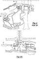
- Figure 1 shows a gas turbine engine 10. As known, a fan section 11 moves air and rotates about an axial center line 12. A compressor section 13, a combustion section 14, and a turbine section 15 are also centered on the axial center line 12. Figure 1 is a highly schematic view, however, it does show the main components of the gas turbine engine. Further, while a particular type of gas turbine engine is illustrated in this figure, it should be understood that the present invention extends to other types of gas turbine engines.
- FIG. 2 shows a detail of a cooling air flow 50 which may pass radially outwardly through an outer cooling air path 52 to a blade outer air seal 53.
- the blade outer air seal 53 is positioned radially outwardly of a rotating turbine blade 62.
- An inner air flow path passes cooling air to a stationary vane 56 and to blade 62.
- FIG. 3 shows an inner cooling air flow 60 passing cooling air to an interior passage within a stationary turbine vane 56.
- all of these cooling air paths supply cooling air to relatively small passages (not shown) within components such as the blade outer air seal 53, the vane 56, or the turbine blade 62.
- Those relatively small cooling air passages can become clogged should impurities such as sand or dirt be included in these cooling air flows.
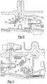
- Figure 4A is an embodiment of a particle collector 74. As shown, the particle collector 74 is attached to a housing member 72 with an axial retention face 76. A split retaining ring 78 is received in a groove 80 in the housing 72, and forces a mounting surface 82 of the particle collector 74 against the axial retention face 76.
- the particle collector 74 includes a first axially and radially inwardly extending surface 84, and a second generally axially extending surface 86. Particle collection materials 88 and 90 are placed on surfaces 86 and 84, respectively.
- the disclosed materials 88 and 90 have a honeycombed shape with intersecting walls 92 and 94, defining a plurality of collection spaces 96. The dirt or other impurities is received within these collection spaces 96.
- Figure 5 shows another embodiment, which is similar to the Figure 4A embodiment, however, a flow guide 100 has a ramped surface 102 to guide the heavier dirt-laden air radially outwardly.
- Figure 6 shows yet another embodiment wherein the particle collector 104 has only a single surface 90.
- Figure 7 shows yet another embodiment 150, wherein a metering hole 152 controls cooling air flow.
- a metering hole 152 controls cooling air flow.
- particle collection materials 156 and 158 are placed in the path of an air flow approaching the metering hole 152.
- a radially outermost portion of the material 158 partially "shadows" the metering hole 152.
- a projected cross-sectional area of the metering hole 152 would pass through a portion of the collection material 158.
- each of the collection material in the various embodiments is such that the collection materials lie on a plane having at least a component in a direction parallel to the axial center line of the gas turbine engine (line 12 - see Figure 1). Further, many of the materials are in a plane that has both a component in that direction, and a component perpendicular to that direction. These orientations are believed the most effective in removing impurities from the air, and retaining those impurities in the collection spaces.
- the particle collectors are preferably honeycombed, and may have as an example, a cell size of .062" (1.57 mm) nominal hexagonal shape. Thicknesses of .0037-.0043" (0.094 mm - 0.11 mm) are used in the prior abradable seal material. However, other sizes may be utilized. Moreover, while honeycombs are disclosed, other shapes having a plurality of dirt collection spaces can be utilized.
Landscapes
- Engineering & Computer Science (AREA)
- Chemical & Material Sciences (AREA)
- Combustion & Propulsion (AREA)
- Mechanical Engineering (AREA)
- General Engineering & Computer Science (AREA)
- Turbine Rotor Nozzle Sealing (AREA)
- Filtering Materials (AREA)
Applications Claiming Priority (1)
| Application Number | Priority Date | Filing Date | Title |
|---|---|---|---|
| US11/350,494 US7770375B2 (en) | 2006-02-09 | 2006-02-09 | Particle collector for gas turbine engine |
Publications (3)
| Publication Number | Publication Date |
|---|---|
| EP1818512A2 true EP1818512A2 (fr) | 2007-08-15 |
| EP1818512A3 EP1818512A3 (fr) | 2010-09-08 |
| EP1818512B1 EP1818512B1 (fr) | 2013-01-02 |
Family
ID=37983449
Family Applications (1)
| Application Number | Title | Priority Date | Filing Date |
|---|---|---|---|
| EP07250501A Ceased EP1818512B1 (fr) | 2006-02-09 | 2007-02-07 | Collecteur de particules pour moteur de turbine à gaz |
Country Status (3)
| Country | Link |
|---|---|
| US (1) | US7770375B2 (fr) |
| EP (1) | EP1818512B1 (fr) |
| JP (1) | JP2007211771A (fr) |
Cited By (3)
| Publication number | Priority date | Publication date | Assignee | Title |
|---|---|---|---|---|
| WO2011115880A1 (fr) * | 2010-03-18 | 2011-09-22 | General Electric Company | Crochet d'enveloppe de turbine doté d'un filtre contre les débris |
| EP3156610A1 (fr) * | 2015-10-15 | 2017-04-19 | General Electric Company | Ensemble de virole pour moteur à turbine à gaz |
| EP3409907A1 (fr) * | 2017-05-30 | 2018-12-05 | United Technologies Corporation | Agencement de refroidissement pour un moteur à turbine et moteur à turbine associé |
Families Citing this family (26)
| Publication number | Priority date | Publication date | Assignee | Title |
|---|---|---|---|---|
| US8240121B2 (en) * | 2007-11-20 | 2012-08-14 | United Technologies Corporation | Retrofit dirt separator for gas turbine engine |
| US10286407B2 (en) | 2007-11-29 | 2019-05-14 | General Electric Company | Inertial separator |
| US9869250B2 (en) | 2014-05-20 | 2018-01-16 | United Technologies Corporation | Particle tolerant turboshaft engine |
| US9915176B2 (en) | 2014-05-29 | 2018-03-13 | General Electric Company | Shroud assembly for turbine engine |
| WO2016025056A2 (fr) | 2014-05-29 | 2016-02-18 | General Electric Company | Moteur de turbine, et épurateurs de particules pour celui-ci |
| WO2016032585A2 (fr) | 2014-05-29 | 2016-03-03 | General Electric Company | Moteur à turbine, composants et leurs procédés de refroidissement |
| US11033845B2 (en) | 2014-05-29 | 2021-06-15 | General Electric Company | Turbine engine and particle separators therefore |
| US10323573B2 (en) | 2014-07-31 | 2019-06-18 | United Technologies Corporation | Air-driven particle pulverizer for gas turbine engine cooling fluid system |
| US10167725B2 (en) | 2014-10-31 | 2019-01-01 | General Electric Company | Engine component for a turbine engine |
| US10036319B2 (en) | 2014-10-31 | 2018-07-31 | General Electric Company | Separator assembly for a gas turbine engine |
| US10012147B2 (en) | 2015-08-17 | 2018-07-03 | United Technologies Corporation | Apparatus and method for air particle separator in gas turbine engine |
| US10835848B2 (en) | 2015-09-21 | 2020-11-17 | Raytheon Technologies Corporation | Apparatus and method for air particle capture in a gas turbine engine |
| US10202903B2 (en) | 2015-09-22 | 2019-02-12 | United Technologies Corporation | Apparatus and method for air particle separation in a gas turbine engine |
| US10428664B2 (en) | 2015-10-15 | 2019-10-01 | General Electric Company | Nozzle for a gas turbine engine |
| JP6563312B2 (ja) * | 2015-11-05 | 2019-08-21 | 川崎重工業株式会社 | ガスタービンエンジンの抽気構造 |
| US10704425B2 (en) | 2016-07-14 | 2020-07-07 | General Electric Company | Assembly for a gas turbine engine |
| US10508626B2 (en) * | 2016-10-14 | 2019-12-17 | Pratt & Whitney Canada Corp. | Auxiliary power unit inlet assembly with filter |
| US10508628B2 (en) * | 2016-10-14 | 2019-12-17 | Pratt & Whitney Canada Corp. | Auxiliary power unit inlet assembly with particle separator |
| US10513344B2 (en) * | 2016-10-14 | 2019-12-24 | Pratt & Whitney Canada Corp. | Auxiliary power unit assembly with removable inlet filter |
| US10322621B2 (en) * | 2017-02-15 | 2019-06-18 | Hamilton Sundstrand Corporation | Inertial particle separator for air cycle machine |
| US10427075B2 (en) | 2017-06-20 | 2019-10-01 | United Technologies Corporation | Debris strainer for gas turbine engine cooling flow |
| US10668486B2 (en) | 2017-07-12 | 2020-06-02 | Hamilton Sundstrand Corporation | Water extractor |
| WO2022224871A1 (fr) * | 2021-04-19 | 2022-10-27 | 三菱パワー株式会社 | Ensemble bague d'aube, turbine à gaz, et procédé de remise à neuf d'une turbine à gaz |
| US11668237B2 (en) | 2021-08-10 | 2023-06-06 | General Electric Company | Multi-stage inlet particle separator for rotary engines |
| US12404806B2 (en) | 2021-12-15 | 2025-09-02 | Rtx Corporation | High pressure turbine dirt blocker |
| CN119878589B (zh) * | 2025-03-03 | 2025-12-26 | 中国航发湖南动力机械研究所 | 离心叶轮及发动机 |
Citations (1)
| Publication number | Priority date | Publication date | Assignee | Title |
|---|---|---|---|---|
| EP0957237A2 (fr) | 1998-05-13 | 1999-11-17 | GHH BORSIG Turbomaschinen GmbH | Refroidissement d'un joint à nid d'abeille dans une turbine à gaz |
Family Cites Families (14)
| Publication number | Priority date | Publication date | Assignee | Title |
|---|---|---|---|---|
| US3483676A (en) * | 1967-09-29 | 1969-12-16 | Gen Electric | Helicopter engine air inlets |
| US3673771A (en) * | 1970-11-23 | 1972-07-04 | Avco Corp | Multi-channel particle separator |
| US3970439A (en) * | 1973-10-15 | 1976-07-20 | Avco Corporation | Particle separator |
| US4304094A (en) * | 1979-11-16 | 1981-12-08 | United Technologies Corp. | Engine air particle separator for use with gas turbine engine |
| US4798047A (en) * | 1983-12-19 | 1989-01-17 | Elliott Turbomachinery Co., Inc. | Particulate collection and cooling in a turbomachine |
| US4896510A (en) * | 1987-02-06 | 1990-01-30 | General Electric Company | Combustor liner cooling arrangement |
| US4767425A (en) * | 1987-07-06 | 1988-08-30 | The United States Of America As Represented By The Secretary Of The Army | Aspirator mechanism for turbine engine air cleaner |
| JP2675391B2 (ja) | 1989-03-22 | 1997-11-12 | 株式会社日立製作所 | ガスタービン |
| IL96886A (en) * | 1991-01-06 | 1994-08-26 | Israel Aircraft Ind Ltd | Apparatus for separating relatively more dense particulate matter from a relatively less dense fluid flow |
| JPH0633981A (ja) | 1992-07-10 | 1994-02-08 | Mazda Motor Corp | 車両の振動低減装置 |
| US6019575A (en) | 1997-09-12 | 2000-02-01 | United Technologies Corporation | Erosion energy dissipater |
| US6398837B1 (en) * | 2000-06-05 | 2002-06-04 | Siemens Westinghouse Power Corporation | Metal-ceramic composite candle filters |
| AU2002366846A1 (en) * | 2001-12-13 | 2003-07-09 | Alstom Technology Ltd | Hot gas path subassembly of a gas turbine |
| US7008181B2 (en) * | 2003-09-04 | 2006-03-07 | General Electric Co. | Gas turbine engine air baffle for a rotating cavity |
-
2006
- 2006-02-09 US US11/350,494 patent/US7770375B2/en not_active Expired - Fee Related
-
2007
- 2007-02-02 JP JP2007023720A patent/JP2007211771A/ja active Pending
- 2007-02-07 EP EP07250501A patent/EP1818512B1/fr not_active Ceased
Patent Citations (1)
| Publication number | Priority date | Publication date | Assignee | Title |
|---|---|---|---|---|
| EP0957237A2 (fr) | 1998-05-13 | 1999-11-17 | GHH BORSIG Turbomaschinen GmbH | Refroidissement d'un joint à nid d'abeille dans une turbine à gaz |
Cited By (6)
| Publication number | Priority date | Publication date | Assignee | Title |
|---|---|---|---|---|
| WO2011115880A1 (fr) * | 2010-03-18 | 2011-09-22 | General Electric Company | Crochet d'enveloppe de turbine doté d'un filtre contre les débris |
| EP3156610A1 (fr) * | 2015-10-15 | 2017-04-19 | General Electric Company | Ensemble de virole pour moteur à turbine à gaz |
| CN106801630A (zh) * | 2015-10-15 | 2017-06-06 | 通用电气公司 | 用于燃气涡轮发动机的护罩组件 |
| CN106801630B (zh) * | 2015-10-15 | 2020-06-05 | 通用电气公司 | 用于燃气涡轮发动机的护罩组件 |
| EP3409907A1 (fr) * | 2017-05-30 | 2018-12-05 | United Technologies Corporation | Agencement de refroidissement pour un moteur à turbine et moteur à turbine associé |
| US10626751B2 (en) | 2017-05-30 | 2020-04-21 | United Technologies Corporation | Turbine cooling air metering arrangement |
Also Published As
| Publication number | Publication date |
|---|---|
| EP1818512A3 (fr) | 2010-09-08 |
| EP1818512B1 (fr) | 2013-01-02 |
| JP2007211771A (ja) | 2007-08-23 |
| US20070183887A1 (en) | 2007-08-09 |
| US7770375B2 (en) | 2010-08-10 |
Similar Documents
| Publication | Publication Date | Title |
|---|---|---|
| EP1818512B1 (fr) | Collecteur de particules pour moteur de turbine à gaz | |
| EP1793086B1 (fr) | Aube de turbine à gaz avec un déflecteur de particules | |
| JP5497150B2 (ja) | 圧縮機のタンデムロータに内部フィルタを有する抽気 | |
| EP1967700A2 (fr) | Joint d'étanchéité à labyrinthe pourvu de poches et de lamelles inclinées, et moteur de turbine à gaz muni d'un tel joint | |
| EP2305963A2 (fr) | Dispositif séparateur | |
| EP2009236B1 (fr) | Rotor de turbine et moteur à turbine à gaz associé | |
| US7284953B2 (en) | Dirt separator for gas turbine air supply | |
| CN109139261B (zh) | 涡轮机械及其所用的颗粒分离器系统和移除颗粒的方法 | |
| US12345200B2 (en) | Particle separators for turbomachines and method of operating the same | |
| CN110139976B (zh) | 用于涡轮发动机的颗粒分离器组件 | |
| CN204877682U (zh) | 用于涡轮机的碎片清除系统及对应的涡轮机 | |
| EP2557272B1 (fr) | Etage rotorique de moteur à turbine à gaz et procédé associé de séparation d'huile d'un flux interne | |
| CN106907194B (zh) | 用于改进的流量的分段微通道 | |
| CN107084004A (zh) | 用于涡轮发动机部件的冲击孔 | |
| US12286901B2 (en) | Turbine engine component with deflector | |
| EP2935833A1 (fr) | Moteur à turbine à gaz comprenant un échangeur thermique à pré-diffuseur | |
| EP3557001B1 (fr) | Agencement de refroidissement pour composants de moteur | |
| US11015469B2 (en) | Coolant airflow assembly particulate filter with panels in series | |
| EP3431710A1 (fr) | Écran de protection pour profil aérodynamique de moteur à turbine | |
| US20120312027A1 (en) | Flow discharge device | |
| EP3409907B1 (fr) | Agencement de refroidissement pour un moteur à turbine | |
| EP4556690A1 (fr) | Séparateur cyclonique pour un support d'étanchéité d'une turbine à gaz | |
| CN120026991A (zh) | 具有颗粒偏转器组件的涡轮发动机 | |
| RU2005102328A (ru) | Газотурбинный двигатель |
Legal Events
| Date | Code | Title | Description |
|---|---|---|---|
| PUAI | Public reference made under article 153(3) epc to a published international application that has entered the european phase |
Free format text: ORIGINAL CODE: 0009012 |
|
| AK | Designated contracting states |
Kind code of ref document: A2 Designated state(s): AT BE BG CH CY CZ DE DK EE ES FI FR GB GR HU IE IS IT LI LT LU LV MC NL PL PT RO SE SI SK TR |
|
| AX | Request for extension of the european patent |
Extension state: AL BA HR MK YU |
|
| PUAL | Search report despatched |
Free format text: ORIGINAL CODE: 0009013 |
|
| AK | Designated contracting states |
Kind code of ref document: A3 Designated state(s): AT BE BG CH CY CZ DE DK EE ES FI FR GB GR HU IE IS IT LI LT LU LV MC NL PL PT RO SE SI SK TR |
|
| AX | Request for extension of the european patent |
Extension state: AL BA HR MK RS |
|
| 17P | Request for examination filed |
Effective date: 20110308 |
|
| 17Q | First examination report despatched |
Effective date: 20110408 |
|
| AKX | Designation fees paid |
Designated state(s): DE GB |
|
| GRAP | Despatch of communication of intention to grant a patent |
Free format text: ORIGINAL CODE: EPIDOSNIGR1 |
|
| GRAS | Grant fee paid |
Free format text: ORIGINAL CODE: EPIDOSNIGR3 |
|
| GRAA | (expected) grant |
Free format text: ORIGINAL CODE: 0009210 |
|
| AK | Designated contracting states |
Kind code of ref document: B1 Designated state(s): DE GB |
|
| REG | Reference to a national code |
Ref country code: GB Ref legal event code: FG4D |
|
| REG | Reference to a national code |
Ref country code: DE Ref legal event code: R081 Ref document number: 602007027736 Country of ref document: DE Owner name: UNITED TECHNOLOGIES CORP. (N.D.GES.D. STAATES , US Free format text: FORMER OWNER: UNITED TECHNOLOGIES INC., HARTFORD, CONN., US |
|
| REG | Reference to a national code |
Ref country code: DE Ref legal event code: R082 Ref document number: 602007027736 Country of ref document: DE Representative=s name: SCHMITT-NILSON SCHRAUD WAIBEL WOHLFROM PATENTA, DE Ref country code: DE Ref legal event code: R082 Ref document number: 602007027736 Country of ref document: DE Representative=s name: KSNH PATENTANWAELTE KLUNKER & KOLLEGEN, DE Ref country code: DE Ref legal event code: R082 Ref document number: 602007027736 Country of ref document: DE Representative=s name: KSNH PATENTANWAELTE KLUNKER/SCHMITT-NILSON/HIR, DE |
|
| REG | Reference to a national code |
Ref country code: DE Ref legal event code: R096 Ref document number: 602007027736 Country of ref document: DE Effective date: 20130314 |
|
| PLBE | No opposition filed within time limit |
Free format text: ORIGINAL CODE: 0009261 |
|
| STAA | Information on the status of an ep patent application or granted ep patent |
Free format text: STATUS: NO OPPOSITION FILED WITHIN TIME LIMIT |
|
| 26N | No opposition filed |
Effective date: 20131003 |
|
| REG | Reference to a national code |
Ref country code: DE Ref legal event code: R097 Ref document number: 602007027736 Country of ref document: DE Effective date: 20131003 |
|
| REG | Reference to a national code |
Ref country code: DE Ref legal event code: R082 Ref document number: 602007027736 Country of ref document: DE Representative=s name: SCHMITT-NILSON SCHRAUD WAIBEL WOHLFROM PATENTA, DE |
|
| REG | Reference to a national code |
Ref country code: DE Ref legal event code: R082 Ref document number: 602007027736 Country of ref document: DE Representative=s name: SCHMITT-NILSON SCHRAUD WAIBEL WOHLFROM PATENTA, DE Ref country code: DE Ref legal event code: R081 Ref document number: 602007027736 Country of ref document: DE Owner name: UNITED TECHNOLOGIES CORP. (N.D.GES.D. STAATES , US Free format text: FORMER OWNER: UNITED TECHNOLOGIES CORPORATION, HARTFORD, CONN., US |
|
| PGFP | Annual fee paid to national office [announced via postgrant information from national office to epo] |
Ref country code: GB Payment date: 20210120 Year of fee payment: 15 Ref country code: DE Payment date: 20210120 Year of fee payment: 15 |
|
| REG | Reference to a national code |
Ref country code: DE Ref legal event code: R119 Ref document number: 602007027736 Country of ref document: DE |
|
| REG | Reference to a national code |
Ref country code: DE Ref legal event code: R081 Ref document number: 602007027736 Country of ref document: DE Owner name: RAYTHEON TECHNOLOGIES CORPORATION (N.D.GES.D.S, US Free format text: FORMER OWNER: UNITED TECHNOLOGIES CORP. (N.D.GES.D. STAATES DELAWARE), FARMINGTON, CONN., US |
|
| GBPC | Gb: european patent ceased through non-payment of renewal fee |
Effective date: 20220207 |
|
| PG25 | Lapsed in a contracting state [announced via postgrant information from national office to epo] |
Ref country code: GB Free format text: LAPSE BECAUSE OF NON-PAYMENT OF DUE FEES Effective date: 20220207 Ref country code: DE Free format text: LAPSE BECAUSE OF NON-PAYMENT OF DUE FEES Effective date: 20220901 |