EP1818533A2 - Système de sécurité pour un piège d'hydrocarbure - Google Patents
Système de sécurité pour un piège d'hydrocarbure Download PDFInfo
- Publication number
- EP1818533A2 EP1818533A2 EP07100649A EP07100649A EP1818533A2 EP 1818533 A2 EP1818533 A2 EP 1818533A2 EP 07100649 A EP07100649 A EP 07100649A EP 07100649 A EP07100649 A EP 07100649A EP 1818533 A2 EP1818533 A2 EP 1818533A2
- Authority
- EP
- European Patent Office
- Prior art keywords
- air
- air tube
- hydrocarbon trap
- trap
- hydrocarbon
- Prior art date
- Legal status (The legal status is an assumption and is not a legal conclusion. Google has not performed a legal analysis and makes no representation as to the accuracy of the status listed.)
- Withdrawn
Links
- 239000004215 Carbon black (E152) Substances 0.000 title claims abstract description 81
- 229930195733 hydrocarbon Natural products 0.000 title claims abstract description 81
- 150000002430 hydrocarbons Chemical class 0.000 title claims abstract description 80
- 238000002485 combustion reaction Methods 0.000 claims abstract description 6
- 239000000758 substrate Substances 0.000 claims description 11
- 239000002184 metal Substances 0.000 claims description 8
- 238000000034 method Methods 0.000 claims description 8
- 239000004033 plastic Substances 0.000 description 13
- OKTJSMMVPCPJKN-UHFFFAOYSA-N Carbon Chemical compound [C] OKTJSMMVPCPJKN-UHFFFAOYSA-N 0.000 description 4
- 238000001746 injection moulding Methods 0.000 description 4
- 239000003463 adsorbent Substances 0.000 description 3
- 239000007789 gas Substances 0.000 description 3
- 239000000463 material Substances 0.000 description 3
- 230000000694 effects Effects 0.000 description 2
- 230000006698 induction Effects 0.000 description 2
- 239000007788 liquid Substances 0.000 description 2
- 230000035882 stress Effects 0.000 description 2
- 230000007704 transition Effects 0.000 description 2
- 238000011144 upstream manufacturing Methods 0.000 description 2
- 239000010457 zeolite Substances 0.000 description 2
- 230000000274 adsorptive effect Effects 0.000 description 1
- 230000000712 assembly Effects 0.000 description 1
- 238000000429 assembly Methods 0.000 description 1
- 239000012876 carrier material Substances 0.000 description 1
- 230000015556 catabolic process Effects 0.000 description 1
- 239000011248 coating agent Substances 0.000 description 1
- 238000000576 coating method Methods 0.000 description 1
- 230000001010 compromised effect Effects 0.000 description 1
- 238000001816 cooling Methods 0.000 description 1
- 238000006731 degradation reaction Methods 0.000 description 1
- 238000003795 desorption Methods 0.000 description 1
- 238000003618 dip coating Methods 0.000 description 1
- 238000005553 drilling Methods 0.000 description 1
- 239000000428 dust Substances 0.000 description 1
- 238000004070 electrodeposition Methods 0.000 description 1
- 230000007613 environmental effect Effects 0.000 description 1
- 238000001914 filtration Methods 0.000 description 1
- 239000000446 fuel Substances 0.000 description 1
- 239000002828 fuel tank Substances 0.000 description 1
- 238000010438 heat treatment Methods 0.000 description 1
- 125000001183 hydrocarbyl group Chemical group 0.000 description 1
- 238000009434 installation Methods 0.000 description 1
- 239000000203 mixture Substances 0.000 description 1
- 238000005498 polishing Methods 0.000 description 1
- 150000003839 salts Chemical class 0.000 description 1
- 239000007787 solid Substances 0.000 description 1
- 238000005507 spraying Methods 0.000 description 1
- 239000000126 substance Substances 0.000 description 1
- 230000008646 thermal stress Effects 0.000 description 1
- XLYOFNOQVPJJNP-UHFFFAOYSA-N water Substances O XLYOFNOQVPJJNP-UHFFFAOYSA-N 0.000 description 1
Images
Classifications
-
- F—MECHANICAL ENGINEERING; LIGHTING; HEATING; WEAPONS; BLASTING
- F02—COMBUSTION ENGINES; HOT-GAS OR COMBUSTION-PRODUCT ENGINE PLANTS
- F02M—SUPPLYING COMBUSTION ENGINES IN GENERAL WITH COMBUSTIBLE MIXTURES OR CONSTITUENTS THEREOF
- F02M35/00—Combustion-air cleaners, air intakes, intake silencers, or induction systems specially adapted for, or arranged on, internal-combustion engines
- F02M35/10—Air intakes; Induction systems
- F02M35/10242—Devices or means connected to or integrated into air intakes; Air intakes combined with other engine or vehicle parts
- F02M35/10281—Means to remove, re-atomise or redistribute condensed fuel; Means to avoid fuel particles from separating from the mixture
-
- B—PERFORMING OPERATIONS; TRANSPORTING
- B01—PHYSICAL OR CHEMICAL PROCESSES OR APPARATUS IN GENERAL
- B01D—SEPARATION
- B01D53/00—Separation of gases or vapours; Recovering vapours of volatile solvents from gases; Chemical or biological purification of waste gases, e.g. engine exhaust gases, smoke, fumes, flue gases, aerosols
- B01D53/02—Separation of gases or vapours; Recovering vapours of volatile solvents from gases; Chemical or biological purification of waste gases, e.g. engine exhaust gases, smoke, fumes, flue gases, aerosols by adsorption, e.g. preparative gas chromatography
- B01D53/04—Separation of gases or vapours; Recovering vapours of volatile solvents from gases; Chemical or biological purification of waste gases, e.g. engine exhaust gases, smoke, fumes, flue gases, aerosols by adsorption, e.g. preparative gas chromatography with stationary adsorbents
- B01D53/0407—Constructional details of adsorbing systems
- B01D53/0415—Beds in cartridges
-
- F—MECHANICAL ENGINEERING; LIGHTING; HEATING; WEAPONS; BLASTING
- F02—COMBUSTION ENGINES; HOT-GAS OR COMBUSTION-PRODUCT ENGINE PLANTS
- F02M—SUPPLYING COMBUSTION ENGINES IN GENERAL WITH COMBUSTIBLE MIXTURES OR CONSTITUENTS THEREOF
- F02M25/00—Engine-pertinent apparatus for adding non-fuel substances or small quantities of secondary fuel to combustion-air, main fuel or fuel-air mixture
- F02M25/08—Engine-pertinent apparatus for adding non-fuel substances or small quantities of secondary fuel to combustion-air, main fuel or fuel-air mixture adding fuel vapours drawn from engine fuel reservoir
- F02M25/0854—Details of the absorption canister
-
- F—MECHANICAL ENGINEERING; LIGHTING; HEATING; WEAPONS; BLASTING
- F02—COMBUSTION ENGINES; HOT-GAS OR COMBUSTION-PRODUCT ENGINE PLANTS
- F02M—SUPPLYING COMBUSTION ENGINES IN GENERAL WITH COMBUSTIBLE MIXTURES OR CONSTITUENTS THEREOF
- F02M33/00—Other apparatus for treating combustion-air, fuel or fuel-air mixture
- F02M33/02—Other apparatus for treating combustion-air, fuel or fuel-air mixture for collecting and returning condensed fuel
- F02M33/04—Other apparatus for treating combustion-air, fuel or fuel-air mixture for collecting and returning condensed fuel returning to the intake passage
-
- F—MECHANICAL ENGINEERING; LIGHTING; HEATING; WEAPONS; BLASTING
- F02—COMBUSTION ENGINES; HOT-GAS OR COMBUSTION-PRODUCT ENGINE PLANTS
- F02M—SUPPLYING COMBUSTION ENGINES IN GENERAL WITH COMBUSTIBLE MIXTURES OR CONSTITUENTS THEREOF
- F02M35/00—Combustion-air cleaners, air intakes, intake silencers, or induction systems specially adapted for, or arranged on, internal-combustion engines
- F02M35/02—Air cleaners
-
- F—MECHANICAL ENGINEERING; LIGHTING; HEATING; WEAPONS; BLASTING
- F02—COMBUSTION ENGINES; HOT-GAS OR COMBUSTION-PRODUCT ENGINE PLANTS
- F02M—SUPPLYING COMBUSTION ENGINES IN GENERAL WITH COMBUSTIBLE MIXTURES OR CONSTITUENTS THEREOF
- F02M35/00—Combustion-air cleaners, air intakes, intake silencers, or induction systems specially adapted for, or arranged on, internal-combustion engines
- F02M35/02—Air cleaners
- F02M35/024—Air cleaners using filters, e.g. moistened
-
- F—MECHANICAL ENGINEERING; LIGHTING; HEATING; WEAPONS; BLASTING
- F02—COMBUSTION ENGINES; HOT-GAS OR COMBUSTION-PRODUCT ENGINE PLANTS
- F02M—SUPPLYING COMBUSTION ENGINES IN GENERAL WITH COMBUSTIBLE MIXTURES OR CONSTITUENTS THEREOF
- F02M35/00—Combustion-air cleaners, air intakes, intake silencers, or induction systems specially adapted for, or arranged on, internal-combustion engines
- F02M35/10—Air intakes; Induction systems
- F02M35/10006—Air intakes; Induction systems characterised by the position of elements of the air intake system in direction of the air intake flow, i.e. between ambient air inlet and supply to the combustion chamber
- F02M35/10019—Means upstream of the fuel injection system, carburettor or plenum chamber
-
- F—MECHANICAL ENGINEERING; LIGHTING; HEATING; WEAPONS; BLASTING
- F02—COMBUSTION ENGINES; HOT-GAS OR COMBUSTION-PRODUCT ENGINE PLANTS
- F02M—SUPPLYING COMBUSTION ENGINES IN GENERAL WITH COMBUSTIBLE MIXTURES OR CONSTITUENTS THEREOF
- F02M35/00—Combustion-air cleaners, air intakes, intake silencers, or induction systems specially adapted for, or arranged on, internal-combustion engines
- F02M35/10—Air intakes; Induction systems
- F02M35/10091—Air intakes; Induction systems characterised by details of intake ducts: shapes; connections; arrangements
- F02M35/10144—Connections of intake ducts to each other or to another device
-
- F—MECHANICAL ENGINEERING; LIGHTING; HEATING; WEAPONS; BLASTING
- F02—COMBUSTION ENGINES; HOT-GAS OR COMBUSTION-PRODUCT ENGINE PLANTS
- F02M—SUPPLYING COMBUSTION ENGINES IN GENERAL WITH COMBUSTIBLE MIXTURES OR CONSTITUENTS THEREOF
- F02M35/00—Combustion-air cleaners, air intakes, intake silencers, or induction systems specially adapted for, or arranged on, internal-combustion engines
- F02M35/10—Air intakes; Induction systems
- F02M35/10314—Materials for intake systems
- F02M35/10321—Plastics; Composites; Rubbers
-
- B—PERFORMING OPERATIONS; TRANSPORTING
- B01—PHYSICAL OR CHEMICAL PROCESSES OR APPARATUS IN GENERAL
- B01D—SEPARATION
- B01D2259/00—Type of treatment
- B01D2259/45—Gas separation or purification devices adapted for specific applications
- B01D2259/4516—Gas separation or purification devices adapted for specific applications for fuel vapour recovery systems
-
- F—MECHANICAL ENGINEERING; LIGHTING; HEATING; WEAPONS; BLASTING
- F02—COMBUSTION ENGINES; HOT-GAS OR COMBUSTION-PRODUCT ENGINE PLANTS
- F02M—SUPPLYING COMBUSTION ENGINES IN GENERAL WITH COMBUSTIBLE MIXTURES OR CONSTITUENTS THEREOF
- F02M35/00—Combustion-air cleaners, air intakes, intake silencers, or induction systems specially adapted for, or arranged on, internal-combustion engines
- F02M35/02—Air cleaners
- F02M35/0201—Housings; Casings; Frame constructions; Lids; Manufacturing or assembling thereof
- F02M35/021—Arrangements of air flow meters in or on air cleaner housings
-
- F—MECHANICAL ENGINEERING; LIGHTING; HEATING; WEAPONS; BLASTING
- F02—COMBUSTION ENGINES; HOT-GAS OR COMBUSTION-PRODUCT ENGINE PLANTS
- F02M—SUPPLYING COMBUSTION ENGINES IN GENERAL WITH COMBUSTIBLE MIXTURES OR CONSTITUENTS THEREOF
- F02M35/00—Combustion-air cleaners, air intakes, intake silencers, or induction systems specially adapted for, or arranged on, internal-combustion engines
- F02M35/10—Air intakes; Induction systems
- F02M35/1034—Manufacturing and assembling intake systems
- F02M35/10347—Moulding, casting or the like
Definitions
- a hydrocarbon trap safety system is installed in an automotive air induction system to secure the trap and reduce hydrocarbon emissions.
- Evaporative emissions are hydrocarbon vapors that are not from the exhaust system but from other sources in a motor vehicle.
- the most significant sources of such evaporative emissions are in the air intake system, in the fuel rail, in the exhaust gas recirculation system and in the fuel tank of a motor vehicle.
- Hydrocarbon traps can be used to adsorb hydrocarbon vapors and reduce hydrocarbon emissions.
- hydrocarbon traps include adsorbents such as zeolites or activated carbon.
- the adsorbents may be contained in or coated on either a permeable support or substrate.
- Hydrocarbon traps can be installed in the air intake system between the air filter and the engine of a vehicle, where they trap hydrocarbon vapors escaping through the air intake system.
- the installation of a hydrocarbon trap at this location is desirable because it is estimated that the air intake system accounts for up to 50% of the total evaporative emissions.
- the trap In use, the trap adsorbs hydrocarbon vapors that escape when the engine stops. When the vehicle is started and driven, the trap releases the hydrocarbon vapors into the engine where it is burned. Capturing and subsequently burning the hydrocarbon vapors can reduce the hydrocarbon emissions of a vehicle.
- Preferred hydrocarbon traps are designed to be tamper-resistant and do not require an on-board diagnostic (OBD) device. Hydrocarbon traps preferably remain operational throughout the life of the vehicle, have little effect on the airflow into the engine, and are insensitive to ice, water, salt, or dust.
- OBD on-board diagnostic
- hydrocarbon traps typically include adsorbents coated on permeable carrier material or substrate.
- the usually made of metal substrate is placed in an air tube, such. B. the outlet channel of the air filter of a vehicle introduced.
- the substrate is introduced into the outlet channel by means of a transition fit so as to prevent the substrate from vibrating. Vibrations can cause unwanted noise or even damage the trap.
- a transitional fit in the exhaust passage ensures that a majority of the gases flowing through the exhaust passage are routed through (instead of around) the hydrocarbon trap, which in turn increases their efficiency.
- the thermal stress on a non-secure clamp for the hydrocarbon trap can result in undesirable results.
- the usually made of plastic outlet channel of an air filter and the metal substrate are subjected to temperature fluctuations, the z. B. caused by environmental conditions or engine operating conditions.
- the plastic usually expands more than the metal. Because the dimensions of the plastic outlet channel expand more than that of the metal substrate, the interfacial fit between the outlet channel and the substrate is compromised, which can lead to unwanted noise, adsorptive degradation and possibly permanent damage to the trap.
- the aim of this invention is to provide an improved arrangement for a hydrocarbon trap for a motor vehicle.
- Another object of the invention is to provide a system with which a hydrocarbon trap is securely fastened in the air intake system of a motor vehicle.
- Another object of the invention is to provide an effective and safe hydrocarbon trap capable of reducing hydrocarbon emissions over the life of a motor vehicle.
- the safety system includes a first air tube adapted to receive a hydrocarbon trap, a second air tube capable of fitting over and latching over the outer surface of the first air tube, and a clamp that is capable of receiving is to fit around both the first and the second air tube and so securely attach the first air tube to the second air tube.
- the first air tube includes an outlet channel of a clean air filter and is made of plastic.
- the second air pipe includes an inlet part of a clean air duct system and is made of rubber.
- the hydrocarbon trap is preferably installed in the air intake system of a motor vehicle between the air filter and the engine.
- the first and second air tubes are specifically configured to operate in conjunction with a permanent clamp for secure attachment of the hydrocarbon trap.
- a plurality eg, three, four, five, or more
- the openings are preferably arranged at regular intervals around the circumference of the first air tube.
- An inner surface of the second air tube includes an equal number of radially inwardly extending, circumferentially spaced protrusions.
- the outlet channel is preferably brought to a temperature which is higher than the temperature of the trap.
- the dimensions of the outlet channel which is preferably made of plastic, expand so much that the tolerance between the outlet channel and the trap is increased.
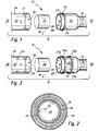
- Fig. 1 shows an exploded view of a safety system for a hydrocarbon trap according to a preferred embodiment.
- Fig. 2 shows a cross-sectional view of a completely assembled security system.
- Fig. 3 shows a perspective view of a completely assembled security system according to another embodiment.
- an exploded perspective view of a portion of an air intake system 10 includes a hydrocarbon trap 12 securing system installed proximate to an automotive engine (not shown).
- the air intake system has the function of filtering the intake air flow and metering it to the engine.
- the air intake system includes an air filter 20 and a clean air duct 30.
- the air cleaner is connected to the clean air duct so that the air cleaned by the air cleaner flows into the engine through the clean air duct.
- the direction of the air flowing through the air intake system is indicated by the arrow A.
- the air filter 20 includes an air cleaner outlet passage 22 disposed downstream (engine side), and the clean air passage 30 includes an inlet for the clean air passage 32 arranged upstream.
- the air intake system 10 may further include an air mass sensor 21. The air mass sensor can be arranged downstream of the air filter in the air flow.
- the outlet channel 22 of the air filter includes an annular portion 24 defining a central cavity 26.
- a plurality of circumferentially spaced openings 27 are formed in the annular portion. The openings extend completely through the annular part. As shown in Fig. 1, three openings are evenly spaced around the part. While three openings are shown, a larger number of openings (eg 4, 5, 6 or more) may be provided. The variety of Openings may be provided along a single circumferential line (as shown) or along multiple circumferential lines as described below.
- each of the openings in the annular portion preferably has a substantially rectangular shape defined by the length dimension, 1, and the width dimension, w, where 1> w.
- the length dimension of each opening in the circumferential direction with respect to the annular part is shown.
- the length dimension of each aperture may be in the axial direction, or the orientation of the apertures may be variable (eg, one aperture may have an orientation different from an adjacent aperture).
- Preferred rectangular openings have a length between about 9 to 11 mm and a width between about 7 to 9 mm, although smaller as well as larger dimensions are conceivable.
- the openings may also have other shapes, such as substantially square or round. Thus, both the number and the spacing as well as the size, the orientation and the shape of the openings can vary.
- a hydrocarbon trap 40 is disposed in a central cavity 26 of the exhaust passage.
- the trap 40 may be inserted into the outlet passage 22 via the open end 28.
- the hydrocarbon trap 40 preferably includes a metal substrate (eg, a porous metal monolith) coated with at least one hydrocarbon adsorbing material.
- the hydrocarbon adsorbing material may include charcoal, activated carbon, zeolites or a mixture thereof, and may be applied to the substrate by known methods such as wash coating, dip coating, electrocoating and spray coating.
- the inner diameter of the annular member In order for the hydrocarbon trap to fit into the annular member, the inner diameter of the annular member must be slightly larger than the outer diameter of the hydrocarbon trap.
- the clearance between the trap and the annular portion is preferably about 1 mm or less (eg, about 0.5 or 0.75 mm), thereby providing a fairly narrow clearance.
- the trap is introduced into the exhaust passage when the temperature of the exhaust passage is greater than the temperature of the trap.
- the exhaust duct which is made of plastic
- the exhaust duct expands easily and the trap can be inserted much easier.
- the hydrocarbon trap may have room temperature, while the plastic outlet passage may be at a temperature higher than room temperature.
- the plastic outlet channel is preferably a plastic part that can be made by injection molding.
- injection molding liquid plastic material is injected into a molded mold, the liquid plastic cools to form a solid part that is taken out of the mold, then it cools down further and optionally a finish can follow (polishing, deburring, etc.).
- the trap may be introduced into the outlet channel during the last cooling.
- the outlet channel and the plurality of openings formed therein are preferably made simultaneously when the outlet channel is made by injection molding.
- the plurality of openings may be formed during injection-following steps, such as burring or drilling.
- the inlet of the clean air line 32 is designed so that it can be pushed over the outer surface of the outlet channel, so as to Air passage from the air filter 20 to the clean air line 30 to form.
- the clean air duct unit including the inlet of the clean air duct is made of rubber.
- the hydrocarbon trap is trapped in the outlet channel of the air filter and downstream of the air filter and upstream of the clean air line.
- the inlet of the clean air duct includes an annular member 34 defining a central cavity 36 adapted to fit over an outer surface of the outlet duct.
- the clear distance between the two parts is preferably about 1 mm or less (eg, about 0.5 or 0.75 mm).
- the inner diameter of the inlet of the clean air duct is preferably slightly larger than the outer diameter of the annular member 24. Since the inlet of the clean air duct is preferably made of rubber, the inlet of the clean air duct be fitted with a transition fit over the outer surface of the annular member.
- a plurality of circumferentially spaced and radially extending projections 37 are formed on an inner surface of the inlet of the clean air duct. As shown in Fig. 1, three protrusions 37 are evenly spaced around the inner surface of the inlet of the clean air duct. While three protrusions are shown, a larger number (eg, 4, 5, 6, or more) may be formed.
- the inlet of the clean air duct and the projections are preferably produced in one piece (eg by means of injection molding). The number of projections is preferably the same as the number of openings, but may be smaller.
- Preferred protrusions have the approximate shape of a rectangular prism defined by a height dimension, h, a linear dimension, 1, and a width dimension, w, such that 1> w.
- the height h is defined as the maximum axial distance that a projection can extend inwardly from the inner surface of the inlet of the clean air duct.
- the projections may also have other shapes, such as trapezoidal, or like a square or annular prism.
- Preferred protrusions have a length between about 7 to 9 mm and a width between about 5 to 7 mm, although smaller and larger dimensions are possible.
- the inlet of the clean air duct is adapted to be slid over an outer surface of the exhaust duct so that each protrusion formed on the inner surface of the clean air duct inlet is aligned with and through the respective opening formed in the annular member extends.
- the protrusions are sized to fully fit through the apertures and extend beyond the inner surface of the central cavity 26 for a limited distance (interference distance).
- a preferred interference distance is about 2 mm. That is, in the absence of a hydrocarbon trap in the central cavity, each projection extends about 2 mm beyond the inner surface of the annular member 24.
- the interference distance may be less than 2 mm (eg 1.5 mm) or greater than 2 mm (eg 2.5 or 3 mm).
- the projections snap into an outer surface of the hydrocarbon trap.
- an axial distal end surface of each projection engages the outer surface of the hydrocarbon trap.
- the clamp 50 may be fitted over the openings 27 (ie, both around the inlet of the clean air duct and around the outlet duct) and tightened to further push the protrusions 27 against the outer surface of the hydrocarbon trap 40 (ie compress) and thus secure the latch in the central cavity 26 of the exhaust duct 22.
- a preferred clamp 50 is a non-removable clamp. Such a clamp is not designed as a user-repairable part and is intended to remain clamped throughout the life of the vehicle.
- each projection is preferably in a state of axial compressive stress (i.e., compressed along the height direction).
- a cross-sectional view of an assembled security system according to one embodiment is shown in FIG.
- the extent to which the protrusions are compressed (due to the inserted trap) is shown by dashed lines.
- the compressive stress applied around the periphery of the hydrocarbon trap secures the trap in the annular part during operation of the motor vehicle, especially at higher temperatures.
- the hydrocarbon trap regenerates itself.
- the hydrocarbon trap adsorbs hydrocarbon vapors released by the engine when the engine is not running and desorbs these hydrocarbon vapors when the engine is running. Desorption of adsorbed hydrocarbon vapors occurs because of the moderate to high flow rate of clean air that is drawn through the trap when the engine is running. Desorbed hydrocarbon vapors flow through the clean air line and into the engine where they are burned. Thus, when the hydrocarbon trap is installed in the air intake system, the trap remains effective throughout the life of the vehicle.
- a hydrocarbon trap is introduced into the open end of an exhaust passage of an air filter, an inlet of the clean air duct is passed over the open end of the air filter Outlet channel pushed so as to enclose the hydrocarbon trap located therein, and a non-removable terminal secures both the outlet channel and the inlet of the clean air line.
- Fig. 3 shows a safety system for a hydrocarbon trap according to another embodiment.
- Two clamps 50a and 50b are provided in the system shown in FIG. Each clamp is secured over a plurality of circumferentially spaced paired protrusions and apertures such that a first series of protrusions 37a pass through a first series of apertures 27a and snap the hydrocarbon trap to a first set of positions about its outer surface, and a second series of protrusions 37b pass through a second series of openings 27b and snap the hydrocarbon trap into a second set of positions about its outer surface.
- the first and second rows of openings are shown offset from one another.
- exhaust duct of the air filter, the inlet of the clean air duct, and the hydrocarbon traps are described herein as including a circular cross section, it will be understood that non-circular (eg, elliptical or polygonal) cross sections may be used.
Landscapes
- Engineering & Computer Science (AREA)
- Chemical & Material Sciences (AREA)
- Combustion & Propulsion (AREA)
- Mechanical Engineering (AREA)
- General Engineering & Computer Science (AREA)
- Analytical Chemistry (AREA)
- General Chemical & Material Sciences (AREA)
- Oil, Petroleum & Natural Gas (AREA)
- Chemical Kinetics & Catalysis (AREA)
- Filtering Of Dispersed Particles In Gases (AREA)
- Separating Particles In Gases By Inertia (AREA)
Applications Claiming Priority (1)
| Application Number | Priority Date | Filing Date | Title |
|---|---|---|---|
| US77101206P | 2006-02-08 | 2006-02-08 |
Publications (2)
| Publication Number | Publication Date |
|---|---|
| EP1818533A2 true EP1818533A2 (fr) | 2007-08-15 |
| EP1818533A3 EP1818533A3 (fr) | 2010-12-01 |
Family
ID=37963520
Family Applications (1)
| Application Number | Title | Priority Date | Filing Date |
|---|---|---|---|
| EP07100649A Withdrawn EP1818533A3 (fr) | 2006-02-08 | 2007-01-17 | Système de sécurité pour un piège d'hydrocarbure |
Country Status (2)
| Country | Link |
|---|---|
| US (1) | US7895983B2 (fr) |
| EP (1) | EP1818533A3 (fr) |
Cited By (5)
| Publication number | Priority date | Publication date | Assignee | Title |
|---|---|---|---|---|
| EP2400141A1 (fr) * | 2010-06-23 | 2011-12-28 | MAHLE International GmbH | Matière première destinée à l'adsorption d'hydrocarbures |
| WO2012049027A1 (fr) * | 2010-10-13 | 2012-04-19 | Mahle International Gmbh | Élément adsorbant, élément filtre annulaire |
| WO2013006360A1 (fr) * | 2011-07-01 | 2013-01-10 | Meadwestvaco Corporation | Dispositifs de régulation d'émission pour systèmes d'admission d'air |
| WO2013006362A1 (fr) * | 2011-07-01 | 2013-01-10 | Meadwestvaco Corporation | Dispositifs de régulation d'émission pour systèmes d'admission d'air |
| CN110418885A (zh) * | 2016-12-20 | 2019-11-05 | K&N工程公司 | 质量空气流传感器和碳氢化合物捕集器组合 |
Families Citing this family (14)
| Publication number | Priority date | Publication date | Assignee | Title |
|---|---|---|---|---|
| US7578285B2 (en) * | 2005-11-17 | 2009-08-25 | Basf Catalysts Llc | Hydrocarbon adsorption filter for air intake system evaporative emission control |
| JP5054446B2 (ja) * | 2007-06-26 | 2012-10-24 | トヨタ車体株式会社 | ダクト取付構造 |
| US8205442B2 (en) * | 2008-06-06 | 2012-06-26 | Visteon Global Technologies, Inc. | Low restriction hydrocarbon trap assembly |
| JP5268514B2 (ja) * | 2008-09-16 | 2013-08-21 | 本田技研工業株式会社 | キャニスタ保持構造 |
| US8372477B2 (en) * | 2009-06-11 | 2013-02-12 | Basf Corporation | Polymeric trap with adsorbent |
| JP5390978B2 (ja) * | 2009-07-31 | 2014-01-15 | 本田技研工業株式会社 | 自動二輪車の蒸発燃料処理装置 |
| US9581115B2 (en) | 2012-03-02 | 2017-02-28 | Ford Global Technologies, Llc | Induction system including a passive-adsorption hydrocarbon trap |
| US9121373B2 (en) * | 2012-03-02 | 2015-09-01 | Ford Global Technologies, Llc | Induction system including a passive-adsorption hydrocarbon trap |
| US20140165933A1 (en) * | 2012-12-19 | 2014-06-19 | Andrew E. Weiss | Duct for engine bay cooling and ventilation |
| DE102015008011B4 (de) * | 2015-06-22 | 2020-12-17 | A. Kayser Automotive Systems Gmbh | Aktivkohlefiltersystem |
| KR102635059B1 (ko) * | 2017-06-28 | 2024-02-08 | 바스프 코포레이션 | 증발 배출 장치 및 흡착제 |
| US11118544B2 (en) | 2018-12-14 | 2021-09-14 | Mahle International Gmbh | Hydrocarbon adsorber on high-frequency resonator |
| US11506158B2 (en) * | 2020-07-17 | 2022-11-22 | Ford Global Technologies, Llc | Tamper resistant hydrocarbon trap for combustion engines |
| DE102021119960A1 (de) * | 2020-08-14 | 2022-02-17 | Mann+Hummel Gmbh | Luftführungsleitung einer Brennkraftmaschine |
Family Cites Families (11)
| Publication number | Priority date | Publication date | Assignee | Title |
|---|---|---|---|---|
| US2386562A (en) * | 1944-05-22 | 1945-10-09 | Frank D Mahoney | Hose coupling |
| US2797111A (en) * | 1952-04-07 | 1957-06-25 | British Tyre & Rubber Company | Fitting for plural layer wire reinforced hoses |
| DE2304990A1 (de) * | 1972-02-01 | 1973-08-16 | Plastic Engineers Ltd | Filtereinheit |
| US4111469A (en) * | 1976-12-23 | 1978-09-05 | Samuel Moore And Company | Hydraulic hose and coupling assembly |
| WO1999014483A1 (fr) * | 1997-09-12 | 1999-03-25 | Donaldson Company, Inc. | Ensemble epurateur d'air et procede correspondant |
| US6464761B1 (en) * | 1999-12-22 | 2002-10-15 | Visteon Global Technologies, Inc. | Air induction filter assembly |
| US6505610B2 (en) * | 2001-05-31 | 2003-01-14 | Siemens Vdo Automotive, Inc. | Engine intake system having a hydrocarbon collection pit |
| US6758885B2 (en) * | 2002-02-07 | 2004-07-06 | Visteon Global Technologies, Inc. | Screened carbon trap protection |
| US6752859B2 (en) * | 2002-10-02 | 2004-06-22 | Delphi Technologies, Inc. | Air cleaner assembly for reducing pollutants from being discharged into the atmosphere |
| WO2004039476A1 (fr) * | 2002-10-28 | 2004-05-13 | Donaldson Company, Inc. | Filtre a air, cartouches de filtres remplaçables et procedes |
| US7547350B2 (en) * | 2005-01-10 | 2009-06-16 | Miniature Precision Components, Inc. | Air induction system with hydrocarbon trap assembly |
-
2007
- 2007-01-17 EP EP07100649A patent/EP1818533A3/fr not_active Withdrawn
- 2007-02-08 US US11/703,795 patent/US7895983B2/en active Active
Cited By (7)
| Publication number | Priority date | Publication date | Assignee | Title |
|---|---|---|---|---|
| EP2400141A1 (fr) * | 2010-06-23 | 2011-12-28 | MAHLE International GmbH | Matière première destinée à l'adsorption d'hydrocarbures |
| WO2012049027A1 (fr) * | 2010-10-13 | 2012-04-19 | Mahle International Gmbh | Élément adsorbant, élément filtre annulaire |
| US9657693B2 (en) | 2010-10-13 | 2017-05-23 | Mahle International Gmbh | Adsorber element, ring filter element |
| WO2013006360A1 (fr) * | 2011-07-01 | 2013-01-10 | Meadwestvaco Corporation | Dispositifs de régulation d'émission pour systèmes d'admission d'air |
| WO2013006362A1 (fr) * | 2011-07-01 | 2013-01-10 | Meadwestvaco Corporation | Dispositifs de régulation d'émission pour systèmes d'admission d'air |
| CN110418885A (zh) * | 2016-12-20 | 2019-11-05 | K&N工程公司 | 质量空气流传感器和碳氢化合物捕集器组合 |
| CN110418885B (zh) * | 2016-12-20 | 2022-07-22 | K&N工程公司 | 质量空气流传感器和碳氢化合物捕集器组合 |
Also Published As
| Publication number | Publication date |
|---|---|
| US20070186904A1 (en) | 2007-08-16 |
| EP1818533A3 (fr) | 2010-12-01 |
| US7895983B2 (en) | 2011-03-01 |
Similar Documents
| Publication | Publication Date | Title |
|---|---|---|
| EP1818533A2 (fr) | Système de sécurité pour un piège d'hydrocarbure | |
| DE112009002126B4 (de) | Filteraufbau mit elliptischer Dichtungsgrenzfläche | |
| DE102014006852B4 (de) | Hohlfilterelement, Filtergehäuse und Filter | |
| DE10358757B4 (de) | Lufteinlasskanalbaugruppe mit Verdunstungsemissionskontrolle | |
| DE10348575B4 (de) | Abgasrückführsystem für einen Verbrennungsmotor | |
| DE102015209681B4 (de) | Abgasbehandlungseinrichtung mit austauschbarem Einsatz | |
| EP0840846A1 (fr) | Unite et systeme a declic pour une unite | |
| EP3026236A1 (fr) | Dispositif d'admission d'air frais | |
| EP1674679B1 (fr) | Moteur à combustion avec dispositif d'air frais et de ventilation | |
| DE102015008011B4 (de) | Aktivkohlefiltersystem | |
| DE102015117600A1 (de) | Rohrbaugruppe mit einem Anschluss | |
| DE10150062A1 (de) | Filtervorrichtung | |
| EP1520977B1 (fr) | Dispositif d'admission pour un dispositif de prépurification en connection avec une enveloppe de ventilateur | |
| DE102013201402A1 (de) | Mischvorrichtung | |
| DE112016006951B4 (de) | Behälter | |
| DE102018004060A1 (de) | Entlüftungseinrichtung für eine Verbrennungskraftmaschine, insbesondere eines Kraftfahrzeugs | |
| EP1210565A2 (fr) | Dispositif pour determiner au moins un parametre d'un melange gaz-liquide en ecoulement ou pour utiliser un rectificateur d'ecoulement comme collecteur de condensation et procede pour condenser un liquide | |
| EP1283351B1 (fr) | Système d'admission pour un moteur à combustion interne | |
| EP1489373A2 (fr) | Echangeur de chaleur à plaques sans enveloppe et avec chambres collectrices | |
| DE102017204785A1 (de) | Venturimodul für ein Verdichtergehäuse | |
| WO2016020162A1 (fr) | Refroidisseur pour refroidir un flux de gaz | |
| EP3510835B1 (fr) | Élément chauffant annulaire | |
| DE102016117575B4 (de) | Luftzufuhrregelsystem für eine Verbrennungskraftmaschine | |
| DE102006027083B4 (de) | Fluid-Filter insbesondere zum Einsatz in einer Fluidleitung in einem Kfz | |
| DE102016213006A1 (de) | Einrichtung zur Geräuschverringerung für eine Unterdruckleitung eines Bremskraftverstärkers |
Legal Events
| Date | Code | Title | Description |
|---|---|---|---|
| PUAI | Public reference made under article 153(3) epc to a published international application that has entered the european phase |
Free format text: ORIGINAL CODE: 0009012 |
|
| AK | Designated contracting states |
Kind code of ref document: A2 Designated state(s): AT BE BG CH CY CZ DE DK EE ES FI FR GB GR HU IE IS IT LI LT LU LV MC NL PL PT RO SE SI SK TR |
|
| AX | Request for extension of the european patent |
Extension state: AL BA HR MK YU |
|
| PUAL | Search report despatched |
Free format text: ORIGINAL CODE: 0009013 |
|
| AK | Designated contracting states |
Kind code of ref document: A3 Designated state(s): AT BE BG CH CY CZ DE DK EE ES FI FR GB GR HU IE IS IT LI LT LU LV MC NL PL PT RO SE SI SK TR |
|
| AX | Request for extension of the european patent |
Extension state: AL BA HR MK RS |
|
| RIC1 | Information provided on ipc code assigned before grant |
Ipc: F02M 33/04 20060101ALI20101028BHEP Ipc: F02M 35/024 20060101ALI20101028BHEP Ipc: F02M 35/02 20060101ALI20101028BHEP Ipc: F02M 35/10 20060101ALI20101028BHEP Ipc: F02M 25/08 20060101AFI20070502BHEP |
|
| 17P | Request for examination filed |
Effective date: 20110131 |
|
| AKX | Designation fees paid |
Designated state(s): AT BE BG CH CY CZ DE DK EE ES FI FR GB GR HU IE IS IT LI LT LU LV MC NL PL PT RO SE SI SK TR |
|
| GRAP | Despatch of communication of intention to grant a patent |
Free format text: ORIGINAL CODE: EPIDOSNIGR1 |
|
| RIC1 | Information provided on ipc code assigned before grant |
Ipc: F02M 33/04 20060101ALI20110715BHEP Ipc: F02M 35/024 20060101ALI20110715BHEP Ipc: F02M 35/02 20060101ALI20110715BHEP Ipc: F02M 35/10 20060101ALI20110715BHEP Ipc: F02M 25/08 20060101AFI20110715BHEP |
|
| STAA | Information on the status of an ep patent application or granted ep patent |
Free format text: STATUS: THE APPLICATION IS DEEMED TO BE WITHDRAWN |
|
| 18D | Application deemed to be withdrawn |
Effective date: 20120105 |