EP1818751B1 - Algorithme de contrôle de cadence - Google Patents
Algorithme de contrôle de cadence Download PDFInfo
- Publication number
- EP1818751B1 EP1818751B1 EP07250147A EP07250147A EP1818751B1 EP 1818751 B1 EP1818751 B1 EP 1818751B1 EP 07250147 A EP07250147 A EP 07250147A EP 07250147 A EP07250147 A EP 07250147A EP 1818751 B1 EP1818751 B1 EP 1818751B1
- Authority
- EP
- European Patent Office
- Prior art keywords
- cycle
- control
- temperature
- control mode
- previous
- Prior art date
- Legal status (The legal status is an assumption and is not a legal conclusion. Google has not performed a legal analysis and makes no representation as to the accuracy of the status listed.)
- Active
Links
Images













Classifications
-
- G—PHYSICS
- G05—CONTROLLING; REGULATING
- G05D—SYSTEMS FOR CONTROLLING OR REGULATING NON-ELECTRIC VARIABLES
- G05D23/00—Control of temperature
- G05D23/19—Control of temperature characterised by the use of electric means
- G05D23/1917—Control of temperature characterised by the use of electric means using digital means
-
- F—MECHANICAL ENGINEERING; LIGHTING; HEATING; WEAPONS; BLASTING
- F24—HEATING; RANGES; VENTILATING
- F24F—AIR-CONDITIONING; AIR-HUMIDIFICATION; VENTILATION; USE OF AIR CURRENTS FOR SCREENING
- F24F11/00—Control or safety arrangements
- F24F11/30—Control or safety arrangements for purposes related to the operation of the system, e.g. for safety or monitoring
-
- F—MECHANICAL ENGINEERING; LIGHTING; HEATING; WEAPONS; BLASTING
- F24—HEATING; RANGES; VENTILATING
- F24F—AIR-CONDITIONING; AIR-HUMIDIFICATION; VENTILATION; USE OF AIR CURRENTS FOR SCREENING
- F24F11/00—Control or safety arrangements
- F24F11/30—Control or safety arrangements for purposes related to the operation of the system, e.g. for safety or monitoring
- F24F11/46—Improving electric energy efficiency or saving
-
- F—MECHANICAL ENGINEERING; LIGHTING; HEATING; WEAPONS; BLASTING
- F24—HEATING; RANGES; VENTILATING
- F24F—AIR-CONDITIONING; AIR-HUMIDIFICATION; VENTILATION; USE OF AIR CURRENTS FOR SCREENING
- F24F11/00—Control or safety arrangements
- F24F11/50—Control or safety arrangements characterised by user interfaces or communication
- F24F11/61—Control or safety arrangements characterised by user interfaces or communication using timers
-
- F—MECHANICAL ENGINEERING; LIGHTING; HEATING; WEAPONS; BLASTING
- F24—HEATING; RANGES; VENTILATING
- F24F—AIR-CONDITIONING; AIR-HUMIDIFICATION; VENTILATION; USE OF AIR CURRENTS FOR SCREENING
- F24F11/00—Control or safety arrangements
- F24F11/62—Control or safety arrangements characterised by the type of control or by internal processing, e.g. using fuzzy logic, adaptive control or estimation of values
-
- F—MECHANICAL ENGINEERING; LIGHTING; HEATING; WEAPONS; BLASTING
- F24—HEATING; RANGES; VENTILATING
- F24F—AIR-CONDITIONING; AIR-HUMIDIFICATION; VENTILATION; USE OF AIR CURRENTS FOR SCREENING
- F24F11/00—Control or safety arrangements
- F24F11/62—Control or safety arrangements characterised by the type of control or by internal processing, e.g. using fuzzy logic, adaptive control or estimation of values
- F24F11/63—Electronic processing
- F24F11/65—Electronic processing for selecting an operating mode
-
- F—MECHANICAL ENGINEERING; LIGHTING; HEATING; WEAPONS; BLASTING
- F24—HEATING; RANGES; VENTILATING
- F24F—AIR-CONDITIONING; AIR-HUMIDIFICATION; VENTILATION; USE OF AIR CURRENTS FOR SCREENING
- F24F2110/00—Control inputs relating to air properties
- F24F2110/10—Temperature
Definitions
- the present invention relates generally to the field of controlling room temperature by either heating or cooling a room.
- Room temperature control typically utilizes a "temperature span" method, in which a temperature range is specified between a setpoint temperature plus a fixed span temperature and the setpoint temperature minus the fixed span temperature.
- a heating unit turns off when the room temperature is higher than the setpoint temperature plus span temperature and turns on when room temperature is lower than the setpoint temperature minus span temperature.
- a cooling unit turns off when the room temperature is lower than the setpoint temperature minus span temperature and turns on when the room temperature is higher than the setpoint temperature plus span temperature.
- EP-A-1072847 discloses an apparatus for intelligent control of a refrigeration system temperature by controlling the speed of a condenser fan in response to the temperature of a condenser of the refrigeration system.
- a controller in response to monitoring a measured temperature of the condenser, controls the condenser fan in one of two modes: fan speed control mode; or pulse-width modulated duty cycle control mode; to maintain the condenser at a desired temperature, the modes being switched at the point where the fan is constantly operated at its minimum speed.
- the present invention provides an apparatus that controls a temperature of a room, the apparatus comprising:
- Figure 1 shows an architecture of an apparatus for controlling a temperature of a room in accordance with an embodiment of the invention.
- Figure 2 shows cycle rate control by a variable span in accordance with an embodiment of the invention.
- Figure 3 shows an adjustment of a cycle time by controlling a total span in accordance with an embodiment of the invention.
- Figure 4 illustrates limiting a multiplicative factor for controlling a total span in accordance with an embodiment of the invention.
- Figure 5 shows cycle rate control by determining an error used for adjusting duty cycle in accordance with an embodiment of the invention.
- Figure 6A shows a variation of room temperature without a controller supervisor in accordance with an embodiment of the invention.
- Figure 6B shows a variation of room temperature with a controller supervisor in accordance with an embodiment of the invention.
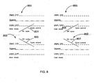
- FIG. 7 illustrates cycle cut capability in accordance with an embodiment of the invention.
- FIG. 8 illustrates cycle extension capability in accordance with an embodiment of the invention.
- Figure 9 shows determining whether a room temperature is excessively outside a temperature band with an embodiment of the invention.
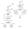
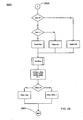
- FIGS. 10-19 show a flow diagram for a cycle rate control process in accordance with an embodiment of the invention.
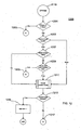
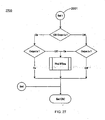
- Figures 20-30 show a flow diagram for a cycle rate control process operating in a variable duty cycle control mode.
- FIG. 1 shows an architecture of an apparatus 100 for controlling a temperature of a room in accordance with an embodiment of the invention.
- Apparatus comprises processing unit 101, environmental control unit 103, temperature sensor 105, and A/D (analog to digital) converter 107.
- processing unit 101 comprises a microprocessor control unit (MCU) that includes a processor and memory that stores computer-executable instructions and data.
- MCU microprocessor control unit
- Environmental control unit 103 may include a furnace to heat the room and/or an air conditioner to cool the room.
- the embodiment of the invention also supports a heat pump, which provides the functionality of both a furnace and an air conditioner.
- the embodiment shown in Figure 1 may support a heating unit and/or a cooling unit.
- the cycle rate is also subject to other factors such as short cycle protection delay and start up delay as will discussed with Figures 10-19 .
- Temperature sensor 105 measures the temperature of a room, thus obtaining feedback from environmental control unit 103.
- a room may assume different entities, including a room in a house, a general location in a house, an office, or an atrium in a building.
- Temperature sensor 105 typically generates an analog signal that is converted into a digital signal by A/D converter 107.
- Processing unit 101 processes the digital signal in accordance with a temperature control process, e.g., flow diagrams 10-19 and flow diagrams 20-30 as will be discussed. The process shown in flow diagrams 10-19 enables a user to adjust the system cycle rate. Temperature control accuracy is also enhanced because the process does not depend on "span temperature".
- a controller supervisor is part of the thermostat software which includes all the I/O (AD, LCD, keyboard, etc.) control and processing as well as the controller (duty cycle control and controller supervisor). This software component runs on processing unit 101.
- Figure 2 shows cycle rate control by a variable span in accordance with an embodiment of the invention.
- An embodiment of the invention provides a method to adjust a cycle rate for controlling a heating system or cooling system. Consequently, the room temperature may be maintained or controlled.
- the cycle rate may be specified as the number of control cycles in one hour with a 50% duty cycle.
- cycle rate control the switching frequency of the heating or cooling unit may be precisely controlled.
- An important function of a thermostat is to maintain the room temperature at the user's desired temperature.
- Two of the methods that can be used in temperature control are span control and duty cycle control. These two methods can be modified to incorporate cycle rate adjustment.
- STemp 203 represents the desired setpoint temperature.
- RTemp 201 represents the room temperature.
- SpanUp 209 is the temperature interval above STemp 203 that the thermostat does not respond to.
- SpanDown 207 is the temperature interval below STemp 203 that the thermostat does not respond to.
- RTemp 201 rises when the heating system is activated and falls when the heating system is deactivated.
- the thermostat switches off the heating system when RTemp 201 rises above STemp + SpanUp, and switches on the heating system when RTemp 201 falls below STemp - SpanDown.
- Figure 3 shows an adjustment of a cycle time by controlling a total span in accordance with an embodiment of the invention.
- the cycle rate is adjusted.
- the time taken in the last control cycle corresponds to ETime 305
- the desired cycle time corresponds to CTime 307.
- the room temperature change can be approximated by ramp responses 301 and 303.
- Figure 4 illustrates limiting a multiplicative factor k 401 for controlling a total span in accordance with an embodiment of the invention.
- k 401 is limited between 0.5 and 2, corresponding to MIN 403 and MAX 405, respectively.
- the range between 0.5 and 2 may be an initial range and may be adjusted to enhance performance.
- S2 is the total span
- SpanUp S ⁇ 2 / 2
- SpanDown S ⁇ 2 - SpanUp
- EQ. 3a and EQ. 3b assume symmetry about the setpoint temperature, the embodiment of the invention also supports an asymmetric relationship in which SpanDown does not equal SpanUp.
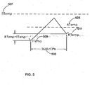
- Figure 5 shows cycle rate control by determining an error used for adjusting duty cycle in accordance with an embodiment of the invention.
- the required cycle rate is large (e.g., 4 CPH or larger)
- the total span becomes small so that the thermostat may not detect the small temperature change accurately, and consequently cycle rate control may become difficult.
- Variable duty cycle control does not depend on determining an accurate total span and is more suitable with a higher cycling rate.
- cycle rate is independent of the room temperature change.
- the duty cycle is adjusted to control and maintain the room temperature at the desired level.
- ATemp 505 is the average temperature of the previous control cycle
- ITemp 509 is the initial room temperature of the previous control cycle
- RTemp 511 is the current room temperature
- STemp 507 is the desired setpoint temperature
- CPH is the cycle per hour setting that corresponds to the cycle time duration 903 (3600/CPH) of the previous control cycle.
- (Rtemp-Itemp) is the temperature change during the previous control cycle.
- the temperature change is then multiplied by a factor that is dependent of the CPH. This factor is used to amplify the small temperature change during large cycle rate.
- the predicted temperature is the sum of the average temperature and the temperature change.
- Duty cycle (Duty_Cycle) can be modified by d2.
- Duty - ⁇ Cycle Duty - ⁇ Cycle - d ⁇ 2
- Duty - ⁇ Cycle Duty - ⁇ Cycle + d ⁇ 2
- Duty_Cycle is set to 1.0000 for a full turn-on during the control cycle.
- Duty_Cycle is smaller than a certain value, e.g., 0.0625, then Duty_Cycle is set to 0.0000 for a full turn-off during the control cycle.
- short cycle protection and/or minimum cycle time requirements may be met before a new control cycle starts.
- the cycle rate may be lower than the setting if the duty cycle is large.
- Figures 10-19 show an embodiment of the invention that utilizes both variable span control and variable duty cycle control.
- Figures 20-30 show a duty cycle control process operating in a variable duty cycle control mode.
- Figures 10-19 show a flow diagram for a cycle rate control procedure in accordance with an embodiment of the invention.
- Figure 10 shows flow diagram 1000 corresponding to a cycle rate control procedure that is performed during a control cycle in accordance with an embodiment of the invention.
- Flow diagram 1000 is started at the beginning of a control cycle.
- Steps 1001-1007 determine whether to initialize the apparatus (e.g., apparatus 100 as shown in Figure 1 ). If so, steps 1009-1017 are executed.
- setting flag Init 1 resets the temperature control process. Additionally, flag Init may be externally reset.
- step 1005 cycle rate control operates every 4 seconds, although the embodiment may operate at different time intervals. With step 1009, the control output turns off for at least 1 minute after each initialization.
- Step 1011 checks the control mode, which is either the span control mode or the duty cycle control mode depends on the value of CPH, and step 1013 determines whether the control mode has changed.
- the initialization process is executed as shown in Figure 18 as steps 1801-1809. Steps 1019 and 1101-1107 (as shown in Figure 11 ) are subsequently executed. If step 1007 determines that initialization is not to be executed, then steps 1021 and 1109-1119 are executed (as shown in Figure 11 ). When executing steps 1109-1119, either the span control mode or the duty cycle control mode may be performed as will be discussed.
- FIG 11 shows flow diagram 1100, which is a continuation of flow diagram 1000 that is shown in Figure 10 .
- steps 1019 and 1101-1107 are executed if initialization is to be performed. If initialization is not to be performed, then steps 1021 and 1109-1119 are executed.
- counter ETime (corresponding to ETime 305 as shown in Figure 3 is incremented. (Counter ETime measures the elapsed time since the start of the control cycle.)
- counter N is updated every 64 seconds (as determined by step 1111) so that the average temperature ATemp 505 (as shown in Figure 5 ) can be determined during the control cycle. (ATemp may be used only in duty cycle control. ATemp sums up RTemp every 64sec.
- FIG 12 shows flow diagram 1200 for controlling a duty cycle in accordance with an embodiment of the invention.
- ETime (as updated by step 1109 in Figure 11 ) is compared with CTime.
- CTime is the time of the on or off period. It depends on the CPH setting and the duty cycle.) If ETime is less than CTime, steps 1203 and 1403-1407 (as shown in Figure 14 ) are executed. Otherwise, steps 1205-1213 are executed. Steps 1205-1213 are used to check if it can start a new on cycle in cooling mode. For cooling mode there is short cycle protection timer which limits the minimum turn off time.
- step 1211 the control mode is checked as performed by steps 1901-1917 as shown in Figure 19 . If step 1213 determines that the control mode has changed, then flag Init is set to '1' in step 1215. Otherwise, steps 1217 and 1301-1317 are executed as will be discussed in Figure 13 .
- FIG. 13 shows flow diagram 1300, which is a continuation of flow diagram 1200 that is shown in Figure 12 .
- step 1301 the average temperature ATemp 905 is determined.
- step 1303 error E2 is determined in accordance with EQ 4.
- step 1305 the attenuated error d2 is determined in accordance with EQ. 5, and Duty_Cycle is updated in steps 1309 or 1311 in accordance with EQ. 6a or EQ. 6b.
- G is the controller gain and may be user adjustable.
- Steps 1313 - 1315 determine whether Duty_Cycle is too small or too large and set Duty_Cycle accordingly in steps 1319 or 1321.
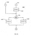
- FIG 14 shows flow diagram 1400, which is a continuation of the flow diagrams 1200 and 1300 that are shown in Figures 12 and 13 .
- Steps 1401-1407 are performed if either steps 1203 or 1317 are executed.
- Step 1203 is executed if the current cycle is continued, and step 1317 is executed if a new cycle is started.
- step 1403 if ETime is less than OnTime, then the control output is set to 'ON' in step 1405. Otherwise, the control output is set to 'OFF' in step 1407. (OnTime is determined in step 1809 as shown in Figure 18 .)
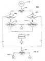
- Figure 15 shows flow diagram 1500 for controlling a total span in accordance with an embodiment of the invention. Steps 1501-1515 are executed if the control mode equals the span control mode. Steps 1503-1505 and 1509-1511 determine if the current temperature RTemp is within a specified temperature range.
- FIG 16 shows flow diagram 1600, which is a continuation of flow diagram 1500 that is shown in Figure 15 .
- Steps 1601-1619 are executed only if a new cycle is to be started, i.e., the output needs to be changed from off to on.
- heat mode it means that the room temp drops below STemp - SpanDown and output is off.
- cool mode it means that the room temp rises over STemp + SpanUp and output is off.
- step 1617 is executed if SpCnt equals 0. Otherwise, SpCnt is decremented in step 1615 and step 1619 is executed.
- SpCnt can be set externally, e.g., after a change of STemp.
- Steps 1711-1713 are performed if either step 1617 or step 1619 is executed.
- SpCnt is set externally to non-zero value to hold the current SpanUp and SpanDown. With some conditions (e.g., where STemp is changed) the current parameters are held for a few cycles for it to stabilize.]
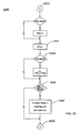
- Figure 18 shows flow diagram 1800 for initializing the procedures shown in Figures 10-17 .
- Initialization process 1801 includes steps 1803-1809.
- Initialization process 1801 initializes variables during the start of each control cycle.
- Initialization process 1811 includes step 1813.
- Initialization process 1811 sets parameters to default values during system start up.
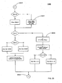
- FIG 19 shows flow diagram 1900 for checking the control mode in accordance with an embodiment of the invention.
- Steps 1903-1917 determine whether the control mode should be changed. In the embodiment, when the cycle rate is less than or equal to 3, the control mode is equal to the span control mode. When the cycle rate is greater than or equal to 4, the control mode is equal to the duty cycle control mode.
- steps 1905 and 1907 CPH_Heat and CPH-Cool are the setting values of the cycle rate in the heating mode and the cooling mode, respectively. If flow diagram 1900 determines to change the control mode, then step 1915 is executed. Otherwise, step 1917 is executed.
- the heating duty cycle may be adjusted to control the room temperature at different conditions.
- the duty cycle is related to the current room temperature, setpoint temperature and room temperature changing rate.
- e proportional error
- r rate error
- d duty cycle
- the duty cycle (d) is determined according to the following observations:
- K1 is a gain constant of proportional error control.
- K2 is a gain constant of rate error control.
- TA is an average room temperature in an on or off cycle.
- TS is a setpoint temperature.
- tC is a cycle time in an on or off cycle.
- d is the duty cycle.
- (TA n - TS n ) is the temperature error in the nth on or off cycle.
- (TA n - TA n-1 ) / [(tC n + tC n - 1 ) / 2] is the rate of change of room temperature in the period from (n-1) th to n th on or off cycle.
- d n+1 is the prediction of the next (n+1) duty cycle according to current duty cycle value, e n and r n .
- Duty cycle d and CPH control cycles per hour are used to find the turn-on time or turn-off time of the next control cycle.
- Cycle denotes a complete on-off cycle.
- On cycle denotes the turn-on period and "off cycle” denotes the turn-off period.)
- cycle rate is a function of duty cycle as well as CPH.
- Cycle rate 2 * d * CPH / Km
- Cycle rate 2 * 1 - d * CPH / Km
- the control of the duty cycle may be relatively slow for certain conditions.
- An example occurs when a user changes the set temperature and the duty cycle needs to substantially change to obtain the new set temperature. e.g., when a user changes the set temperature.
- An additional layer referred as the controller supervisor, is built on top of the basic duty cycle control process.
- the controller supervisor detects these changes and assists the basic duty cycle control process to achieve the new set temperature in a shorter period of time by "cycle cut” or "extend” as will be discussed.
- Another function of the controller supervisor is to ensure that the temperature does not vary too far away from the set temperature by bounding the temperature between "upper limit” and “lower limit” (similar to span control as previously discussed). This is a safety feature to ensure the stability of duty cycle control.
- Figure 6A shows a variation of room temperature 601 without a controller supervisor.
- Room temperature 601 is controlled with respect to setpoint temperature 603.
- the variability of room temperature 601 is not tightly controlled below or above setpoint temperature 603 even though room temperature 601 is approximately centered about setpoint temperature 603.
- Figure 6B shows a variation of room temperature 605 with a controller supervisor in accordance with an embodiment of the invention.
- Control of room temperature 605 is specified with respect to setpoint temperature 607, upper limit 609, and lower limit 611.
- the temperature difference corresponding to upper limit 609 minus lower limit 611 may be referred as the total span.
- Gain constants e.g., K1 and K2 as was discussed
- K1 and K2 adjust the temperature controller response and stability.
- a large gain constant value is required to prevent slow control response.
- a small gain constant is necessary to ensure stable operation.
- a controller supervisor confines the room temperature within two temperature limits: upper limit 609, which is higher than the setpoint temperature, and lower limit 611, which is lower than the setpoint temperature.
- upper limit 609 which is higher than the setpoint temperature
- lower limit 611 which is lower than the setpoint temperature.
- the basic duty cycle control process has the full control of room temperature.
- the controller supervisor takes control of the system or makes an adjustment to the controller to try to force it back into the band.
- Figure 7 illustrates a cycle cut capability in accordance with an embodiment of the invention.
- the controller supervisor continuously checks conditions 751, 753, 755, and 757 for both the heating mode and the cooling mode. If met, the controller supervisor terminates the current control cycle and starts a new control cycle immediately. (The beginning of the new control cycle corresponds to temperature points 701, 703, 705, and 707.) Since the control output is reversed at the start of next control cycle, the room temperature changes to correct the direction of the room temperature.
- the controller supervisor also monitors the required minimum cycle time before cycle cut (to prevent short cycle operation). When starting a new control cycle with the cycle cut capability, the current duty cycle may be far away from the steady state. The controller supervisor can adjust the duty cycle accordingly so that the duty cycle controller can reach steady state in a shorter time.
- the following pseudo code corresponds to a procedure that supports the cycle cut capability.
- FIG. 8 illustrates cycle extension capability in accordance with an embodiment of the invention.
- the controller supervisor continuously checks conditions 851, 853, 855, and 857 for both the heating mode and the cooling mode. At the end of an on or off-cycle, the controller supervisor determines if the current control cycle needs to be extended to drive the room temperature into the temperature band. If so, the controller supervisor extends the current control cycle for 1/8 design cycle time. (The extension of the control cycle corresponds to temperature points 801, 803, 805, and 807.) Similar to cycle cut, when extending the control cycle, the current duty cycle may be far away from the steady state. The controller supervisor can adjust the duty cycle accordingly so that the duty cycle controller can reach steady state in a shorter time.
- the following pseudo code corresponds to a process that supports the cycle extension capability.
- Figure 9 shows a determination of a temperature band that is associated with controlling room temperature 901 in accordance with an embodiment of the invention.
- the controller supervisor confines the room temperature within the temperature band.
- the temperature band is determined according to the maximum temperature swing when the controller is in steady state. During steady state, if duty cycle is smaller than 0.5, the temperature changing rate is larger when the output is turned on. If duty cycle is larger than 0.5, the temperature changing rate is larger when the output is turned off.
- Figures 20-30 show a flow diagram for a cycle rate control procedure operating in a duty cycle control mode.
- system refers to the system selection of a thermostat. Typical selections include “heat,” “cool,” and “off.”
- output refers to an output request of the CRC module.
- step 2001 the cycle rate control (CRC) process commences.
- Step 2003 refers to a routine CRCInit0, which is called when the thermostat first starts up.
- the variable Init is set to '1" in order to reset the control process.
- the variable Init may also be externally set.
- step 2007, the CRC process operates every one second.
- step 2009 the relay output turns off for at least one minute after each initialization.
- Flow diagram 2000 continues for normal CRC control in step 2011 and for initialization in step 2013.
- flow diagram 2100 is a continuation of flow diagram 2000.
- Procedure 2100 performs an initialization for the cycle rate control process.
- N corresponds to the number of temperature samples in variable ATemp
- ATemp is average room temperature
- OATemp is the old (previous) average temperature
- RTemp is the current room temperature
- ETime is the elapsed time from the start of the On/Off cycle
- OETime is ETime of the previous On/Off cycle.
- a procedure (as shown in Figure 28 ) is executed to determine CTime (referring to EQ. 11a, EQ. 11b, EQ. 12a, and EQ. 12b).
- a procedure (as shown in Figure 29 ) is executed to determine Btime.
- ETime is compared with BTime in step 2207 to determine if the temperature band should be updated.
- ETime is compared with CTime in step 2303 to determine whether the current cycle should be completed.
- the initialization procedure is completed and the value of Init is set to '0'. By setting the value of STCnt to non-zero, external parameters are not confirmed is different events, e.g., the system or the set temperature being changed.
- flow diagram 2200 is a continuation of flow diagram 2000.
- Procedure 2200 performs normal cycle rate control during each cycle.
- ETime elapsed time since the start of an on or off cycle
- step 2203 the room temperature is sampled every 64 seconds to determine the average temperature.
- step 2205 determines if the temperature band should be updated. If so, step 2207 determines the temperature band.
- step 2209 procedure 2200 continues to procedure 2300 as shown in Figure 23 .
- flow diagram 2300 is a continuation of flow diagram 2200.
- Procedure 2300 performs cycle cut checking, which is a function of the controller supervisor.
- Step 2301 determines if the set temperature (STemp) has changed and consequently procedure 2300 determines if the current cycle should be cut.
- Procedure 2300 continues to procedure 2400 in step 2305.
- flow diagram 2400 is a continuation of flow diagram 2300.
- Procedure 2400 performs cycle extend checking, which is a function of the controller supervisor.
- step 2401 the value of the output variable is saved since it will be changed if a new on or off cycle is started. (OldOutput is used to check if the output has been changed.)
- step 2403 the room temperature is checked to determine if it is out of the temperature band.
- step 2405 the current on or off cycle is extended and the CTime variable is adjusted to extend the current cycle.
- the Duty variable (corresponding to the duty cycle) is also adjusted to increase the overall response.
- Procedure 2400 continues to procedure 2500 in step 2411.
- flow diagram 2500 is a continuation of flow diagram 2400.
- Procedure 2500 starts a new cycle and determines a new duty cycle.
- step 2501 if the value of STCnt is non-zero, the cycle rate control process does not calculate the average temperature. Rather, the set temperature is used as the average temperature so that the control status does not change excessively. If the value of STCnt is non-zero, the external parameters are not confirmed.
- step 2503 correspond to controller gain settings. The gain settings can be user determined values or can be automatically adjusted by another level of supervision.
- Process 2500 continues to procedure 2600 in step 2505.
- flow diagram 2600 is a continuation of flow diagram 2500.
- Procedure 2600 is a continuation of procedure 2500 for starting a new cycle.
- Procedure 2600 continues to procedure 2700 (as shown in Figure 27 ) in step 2601.
- Flow diagram 2700 is used to check if the output has been changed. If so then a new BTime is calculated.
- Figure 28 shows a flow diagram for the CTime procedure (referenced in step 2105 in Figure 21 ).
- Figure 29 shows a flow diagram for the BTime procedure (referenced in step 2107 in Figure 21 ).
- Figure 30 shows a flow diagram for the CRCInit0 procedure (referenced in step 2003 as shown in Figure 20 ).
- the computer system may include at least one computer such as a microprocessor, digital signal processor, and associated peripheral electronic circuitry.
Landscapes
- Engineering & Computer Science (AREA)
- Mechanical Engineering (AREA)
- General Engineering & Computer Science (AREA)
- Chemical & Material Sciences (AREA)
- Combustion & Propulsion (AREA)
- Signal Processing (AREA)
- Physics & Mathematics (AREA)
- Mathematical Physics (AREA)
- Fuzzy Systems (AREA)
- Human Computer Interaction (AREA)
- General Physics & Mathematics (AREA)
- Automation & Control Theory (AREA)
- Control Of Temperature (AREA)
- Air Conditioning Control Device (AREA)
- Feedback Control In General (AREA)
- Synchronisation In Digital Transmission Systems (AREA)
Claims (8)
- Appareil (100) qui contrôle la température d'une pièce, l'appareil comprenant :un capteur de température (105) qui mesure la température ; etune unité de traitement (101) qui contrôle une unité de contrôle environnemental (103) et qui est configurée pour :(a) déterminer un mode de contrôle ; et(b) si le mode de contrôle est égal à un mode de contrôle de cycle d'utilisation, ajuster un cycle d'utilisation du cycle de contrôle courant en se basant sur une erreur d'un précédent cycle de contrôle ;caractérisé en ce que l'unité de traitement (101) est en outre configurée pour :(c) si le mode de contrôle est égal à un mode de contrôle de plage intermédiaire, ajuster une plage intermédiaire totale courante du cycle de contrôle courant en se basant sur une durée de cycle souhaitée et une durée de cycle précédente en :(c)(i) obtenant une plage intermédiaire totale précédente du cycle de contrôle précédent ; et(c)(ii) multipliant la plage intermédiaire totale précédente par un facteur multiplicatif, dans lequel le facteur multiplicatif est déterminé à partir d'un rapport égal à la durée de cycle souhaitée divisée par la durée de cycle précédente.
- Appareil (100), tel que revendiqué dans la revendication 1, dans lequel l'unité de traitement (101) est en outre configurée pour :(b)(i) déterminer l'erreur à partir d'une température de consigne et d'une température prédite.
- Appareil (100), tel que revendiqué dans la revendication 2, dans lequel la température prédite est basée sur une température moyenne et un changement de température du cycle de contrôle précédent.
- Appareil (100), tel que revendiqué dans la revendication 2 ou la revendication 3, dans lequel l'unité de traitement (101) est en outre configurée pour:(b)(ii) multiplier l'erreur par un facteur d'atténuation.
- Appareil (100), tel que revendiqué dans la revendication 4, dans lequel l'unité de traitement (101) est en outre configurée pour :(b)(iii) ajuster le facteur d'atténuation pour qu'il corresponde à une caractéristique de la pièce.
- Appareil (100), tel que revendiqué dans les revendications 1 à 5, dans lequel l'unité de contrôle environnemental (103) comprend une unité de chauffage.
- Appareil (100), tel que revendiqué dans les revendications 1 à 5, dans lequel l'unité de contrôle environnemental (103) comprend une unité de refroidissement.
- Appareil (100), tel que revendiqué dans les revendications 1 à 7, dans lequel l'unité de traitement (101) est en outre configurée pour :(a)(i) si la cadence de cycle dépasse une limite prédéterminée, définir le mode de contrôle comme étant le mode de contrôle de cycle d'utilisation ; et(a)(ii) si la cadence de cycle est inférieure ou égale à la limite prédéterminée, définir le mode de contrôle comme étant le mode de contrôle de plage intermédiaire.
Applications Claiming Priority (1)
| Application Number | Priority Date | Filing Date | Title |
|---|---|---|---|
| US11/334,259 US7400942B2 (en) | 2006-01-18 | 2006-01-18 | Apparatus for temperature control using a cycle rate control algorithm |
Publications (3)
| Publication Number | Publication Date |
|---|---|
| EP1818751A2 EP1818751A2 (fr) | 2007-08-15 |
| EP1818751A3 EP1818751A3 (fr) | 2008-08-27 |
| EP1818751B1 true EP1818751B1 (fr) | 2011-03-09 |
Family
ID=38016763
Family Applications (1)
| Application Number | Title | Priority Date | Filing Date |
|---|---|---|---|
| EP07250147A Active EP1818751B1 (fr) | 2006-01-18 | 2007-01-16 | Algorithme de contrôle de cadence |
Country Status (4)
| Country | Link |
|---|---|
| US (1) | US7400942B2 (fr) |
| EP (1) | EP1818751B1 (fr) |
| AT (1) | ATE501474T1 (fr) |
| DE (1) | DE602007012950D1 (fr) |
Families Citing this family (17)
| Publication number | Priority date | Publication date | Assignee | Title |
|---|---|---|---|---|
| GB2458425B (en) * | 2007-01-30 | 2012-01-18 | Bradley University | A heat transfer apparatus and methods |
| US8490886B2 (en) * | 2007-06-28 | 2013-07-23 | Westcast, Inc. | Modulating boiler system |
| US8078324B2 (en) * | 2007-07-13 | 2011-12-13 | Cummins Inc. | Method for controlling fixed and removable vehicle HVAC devices |
| US8190296B2 (en) * | 2008-11-11 | 2012-05-29 | Emerson Electric Co. | Apparatus and method for control of a thermostat |
| EP2372483B1 (fr) * | 2010-03-16 | 2012-10-31 | Siemens Aktiengesellschaft | Procédé de régulation d'une grandeur liée au confort dans une pièce |
| US9429962B2 (en) * | 2010-11-19 | 2016-08-30 | Google Inc. | Auto-configuring time-of day for building control unit |
| KR101619034B1 (ko) * | 2012-09-11 | 2016-05-18 | 필립모리스 프로덕츠 에스.에이. | 온도 제어용 전기 히터 제어 장치 및 방법 |
| CN103869846B (zh) * | 2012-12-14 | 2015-11-25 | 中国核动力研究设计院 | 一种主回路冷热段平均温度信号处理方法 |
| TWI608805B (zh) | 2012-12-28 | 2017-12-21 | 菲利浦莫里斯製品股份有限公司 | 加熱型氣溶膠產生裝置及用於產生具有一致性質的氣溶膠之方法 |
| US10808961B2 (en) | 2013-08-30 | 2020-10-20 | James Leych Lau | Energy saving controller |
| US10119719B2 (en) * | 2013-08-30 | 2018-11-06 | James Leych Lau | Energy saving controller |
| GB2540349B (en) * | 2015-07-09 | 2020-03-18 | British Gas Trading Ltd | Temperature control system |
| CN107121993B (zh) * | 2017-04-26 | 2019-01-25 | 上海富士施乐有限公司 | 一种控制复印机的风扇开关的方法 |
| US10989427B2 (en) | 2017-12-20 | 2021-04-27 | Trane International Inc. | HVAC system including smart diagnostic capabilites |
| US12546501B2 (en) | 2020-09-30 | 2026-02-10 | Wall to Wall, LLC | System, method and computer program product for improved climate control |
| EP4222571A1 (fr) * | 2020-09-30 | 2023-08-09 | Veev Group, Inc. | Système, procédé et produit-programme d'ordinateur pour une régulation de climat améliorée |
| CN113503664A (zh) * | 2021-07-23 | 2021-10-15 | 珠海格力电器股份有限公司 | 变频压缩机控制方法及制冷器具 |
Family Cites Families (25)
| Publication number | Priority date | Publication date | Assignee | Title |
|---|---|---|---|---|
| US4292813A (en) | 1979-03-08 | 1981-10-06 | Whirlpool Corporation | Adaptive temperature control system |
| US4270693A (en) * | 1979-08-13 | 1981-06-02 | Johnson Controls, Inc. | Electronic thermostat with heat anticipation and control method incorporating same |
| US4362924A (en) * | 1980-02-15 | 1982-12-07 | Automotive Environmental Systems, Inc. | Temperature achievement controller |
| US4333519A (en) * | 1980-05-08 | 1982-06-08 | Doron Shafrir | Controller for air conditioning units, heating units and the like |
| US4388692A (en) * | 1980-09-03 | 1983-06-14 | Texas Instruments Incorporated | Electronically controlled programmable digital thermostat having variable threshold hysteresis with time |
| US4356962A (en) | 1980-11-14 | 1982-11-02 | Levine Michael R | Thermostat with adaptive operating cycle |
| US4387763A (en) * | 1981-09-14 | 1983-06-14 | Honeywell Inc. | Multistage thermostat using multirate integral action and exponential setpoint change |
| US4460123A (en) * | 1983-10-17 | 1984-07-17 | Roberts-Gordon Appliance Corp. | Apparatus and method for controlling the temperature of a space |
| US4694890A (en) * | 1985-04-15 | 1987-09-22 | Dianalog Systems, Inc. | Analog computer variable duty modulator |
| US4787555A (en) | 1985-09-24 | 1988-11-29 | Alfred T. Newell, III | Environmental control system with condition responsive timer and method |
| US4725001A (en) | 1986-10-17 | 1988-02-16 | Arnold D. Berkeley | Electronic thermostat employing adaptive cycling |
| US4817705A (en) | 1987-07-07 | 1989-04-04 | Honeywell Inc. | Thermostatic control without temperature droop using duty cycle control |
| US4759498A (en) | 1987-07-07 | 1988-07-26 | Honeywell Inc. | Thermostatic control without temperature droop using duty cycle control |
| US4753388A (en) * | 1987-07-24 | 1988-06-28 | Robertshaw Controls Company | Duty-cycle controlling thermostat construction, system utilizing the same and method of making the same |
| US4901918A (en) * | 1989-02-27 | 1990-02-20 | Gas Research Institute | Adaptive anticipator mechanism for limiting room temperature swings |
| US5192020A (en) * | 1991-11-08 | 1993-03-09 | Honeywell Inc. | Intelligent setpoint changeover for a programmable thermostat |
| JP3404150B2 (ja) | 1994-09-28 | 2003-05-06 | 東芝キヤリア株式会社 | 空気調和機及びその制御方法 |
| US6047557A (en) | 1995-06-07 | 2000-04-11 | Copeland Corporation | Adaptive control for a refrigeration system using pulse width modulated duty cycle scroll compressor |
| US6478084B1 (en) * | 1998-04-24 | 2002-11-12 | Steven Winter Associates, Inc. | Energy saving thermostat with a variable deadband |
| US6038871A (en) | 1998-11-23 | 2000-03-21 | General Motors Corporation | Dual mode control of a variable displacement refrigerant compressor |
| US6179213B1 (en) * | 1999-02-09 | 2001-01-30 | Energy Rest, Inc. | Universal accessory for timing and cycling heat, ventilation and air conditioning energy consumption and distribution systems |
| JP2001050599A (ja) * | 1999-07-28 | 2001-02-23 | Johnson Controls Technol Co | ファン速度空冷凝縮器を高機能制御する装置および方法 |
| US6829523B2 (en) * | 2002-02-26 | 2004-12-07 | Thermo King Corporation | Method and apparatus for controlling a transport temperature control unit having selectively programmable temperature ranges |
| US6622500B1 (en) | 2002-05-08 | 2003-09-23 | Delphi Technologies, Inc. | Energy-efficient capacity control method for an air conditioning compressor |
| US6622926B1 (en) * | 2002-10-16 | 2003-09-23 | Emerson Electric Co. | Thermostat with air conditioning load management feature |
-
2006
- 2006-01-18 US US11/334,259 patent/US7400942B2/en active Active
-
2007
- 2007-01-16 DE DE602007012950T patent/DE602007012950D1/de active Active
- 2007-01-16 EP EP07250147A patent/EP1818751B1/fr active Active
- 2007-01-16 AT AT07250147T patent/ATE501474T1/de not_active IP Right Cessation
Also Published As
| Publication number | Publication date |
|---|---|
| DE602007012950D1 (de) | 2011-04-21 |
| EP1818751A2 (fr) | 2007-08-15 |
| ATE501474T1 (de) | 2011-03-15 |
| US20070168084A1 (en) | 2007-07-19 |
| EP1818751A3 (fr) | 2008-08-27 |
| US7400942B2 (en) | 2008-07-15 |
Similar Documents
| Publication | Publication Date | Title |
|---|---|---|
| EP1818751A2 (fr) | Algorithme de contrôle de cadence | |
| KR0164917B1 (ko) | 공기조화기의 운전제어방법 | |
| US6729390B1 (en) | Control for heat pump with auxiliary heat source | |
| CN111623467B (zh) | 一种空调器控制方法及空调器 | |
| JP2000088320A (ja) | 自動換気システム | |
| JPH0694942B2 (ja) | 空気調和機 | |
| KR100452771B1 (ko) | 공기조화기의 제어방법 | |
| JP3571425B2 (ja) | 換気扇の制御装置 | |
| JP3171456B2 (ja) | 空気調和機の運転制御方法 | |
| JP3821104B2 (ja) | 空気調和機の制御装置 | |
| KR100303679B1 (ko) | 에어컨의 취침운전 제어방법 | |
| JP3191795B2 (ja) | マルチ形空気調和機 | |
| JPS6011047A (ja) | 空気調和機の運転制御方法 | |
| JP3078338B2 (ja) | 空気調和機 | |
| JP3149932B2 (ja) | 空気調和機の運転制御方法 | |
| KR0156692B1 (ko) | 에어콘의 온도조절방법 | |
| JPS6018899B2 (ja) | 空気調和機の能力制御方法 | |
| JPH0719575A (ja) | 空気調和機 | |
| JPH10205851A (ja) | 空気調和機の電力デマンド制御装置 | |
| JPH07294030A (ja) | 空気調和機 | |
| KR100512417B1 (ko) | 인버터 공기 조화기의 압축기 운전 제어 방법 | |
| JP2019158182A (ja) | 空調用制御装置とこれを備えた空気調和機 | |
| CN108917085A (zh) | 空调器及其控制方法和控制装置 | |
| JPH05296519A (ja) | 空気調和機 | |
| JPS6338624B2 (fr) |
Legal Events
| Date | Code | Title | Description |
|---|---|---|---|
| PUAI | Public reference made under article 153(3) epc to a published international application that has entered the european phase |
Free format text: ORIGINAL CODE: 0009012 |
|
| AK | Designated contracting states |
Kind code of ref document: A2 Designated state(s): AT BE BG CH CY CZ DE DK EE ES FI FR GB GR HU IE IS IT LI LT LU LV MC NL PL PT RO SE SI SK TR |
|
| AX | Request for extension of the european patent |
Extension state: AL BA HR MK RS |
|
| RIC1 | Information provided on ipc code assigned before grant |
Ipc: F24F 11/00 20060101ALI20080415BHEP Ipc: G05D 23/19 20060101AFI20070523BHEP Ipc: F25B 49/02 20060101ALI20080415BHEP |
|
| PUAL | Search report despatched |
Free format text: ORIGINAL CODE: 0009013 |
|
| AK | Designated contracting states |
Kind code of ref document: A3 Designated state(s): AT BE BG CH CY CZ DE DK EE ES FI FR GB GR HU IE IS IT LI LT LU LV MC NL PL PT RO SE SI SK TR |
|
| AX | Request for extension of the european patent |
Extension state: AL BA HR MK RS |
|
| 17P | Request for examination filed |
Effective date: 20080929 |
|
| 17Q | First examination report despatched |
Effective date: 20081104 |
|
| AKX | Designation fees paid |
Designated state(s): AT BE BG CH CY CZ DE DK EE ES FI FR GB GR HU IE IS IT LI LT LU LV MC NL PL PT RO SE SI SK TR |
|
| GRAP | Despatch of communication of intention to grant a patent |
Free format text: ORIGINAL CODE: EPIDOSNIGR1 |
|
| GRAS | Grant fee paid |
Free format text: ORIGINAL CODE: EPIDOSNIGR3 |
|
| GRAA | (expected) grant |
Free format text: ORIGINAL CODE: 0009210 |
|
| AK | Designated contracting states |
Kind code of ref document: B1 Designated state(s): AT BE BG CH CY CZ DE DK EE ES FI FR GB GR HU IE IS IT LI LT LU LV MC NL PL PT RO SE SI SK TR |
|
| REG | Reference to a national code |
Ref country code: GB Ref legal event code: FG4D |
|
| REG | Reference to a national code |
Ref country code: CH Ref legal event code: EP |
|
| REG | Reference to a national code |
Ref country code: IE Ref legal event code: FG4D |
|
| REF | Corresponds to: |
Ref document number: 602007012950 Country of ref document: DE Date of ref document: 20110421 Kind code of ref document: P |
|
| REG | Reference to a national code |
Ref country code: DE Ref legal event code: R096 Ref document number: 602007012950 Country of ref document: DE Effective date: 20110421 |
|
| REG | Reference to a national code |
Ref country code: NL Ref legal event code: VDEP Effective date: 20110309 |
|
| PG25 | Lapsed in a contracting state [announced via postgrant information from national office to epo] |
Ref country code: ES Free format text: LAPSE BECAUSE OF FAILURE TO SUBMIT A TRANSLATION OF THE DESCRIPTION OR TO PAY THE FEE WITHIN THE PRESCRIBED TIME-LIMIT Effective date: 20110620 Ref country code: LV Free format text: LAPSE BECAUSE OF FAILURE TO SUBMIT A TRANSLATION OF THE DESCRIPTION OR TO PAY THE FEE WITHIN THE PRESCRIBED TIME-LIMIT Effective date: 20110309 Ref country code: SE Free format text: LAPSE BECAUSE OF FAILURE TO SUBMIT A TRANSLATION OF THE DESCRIPTION OR TO PAY THE FEE WITHIN THE PRESCRIBED TIME-LIMIT Effective date: 20110309 Ref country code: GR Free format text: LAPSE BECAUSE OF FAILURE TO SUBMIT A TRANSLATION OF THE DESCRIPTION OR TO PAY THE FEE WITHIN THE PRESCRIBED TIME-LIMIT Effective date: 20110610 Ref country code: LT Free format text: LAPSE BECAUSE OF FAILURE TO SUBMIT A TRANSLATION OF THE DESCRIPTION OR TO PAY THE FEE WITHIN THE PRESCRIBED TIME-LIMIT Effective date: 20110309 |
|
| LTIE | Lt: invalidation of european patent or patent extension |
Effective date: 20110309 |
|
| PG25 | Lapsed in a contracting state [announced via postgrant information from national office to epo] |
Ref country code: FI Free format text: LAPSE BECAUSE OF FAILURE TO SUBMIT A TRANSLATION OF THE DESCRIPTION OR TO PAY THE FEE WITHIN THE PRESCRIBED TIME-LIMIT Effective date: 20110309 Ref country code: NL Free format text: LAPSE BECAUSE OF FAILURE TO SUBMIT A TRANSLATION OF THE DESCRIPTION OR TO PAY THE FEE WITHIN THE PRESCRIBED TIME-LIMIT Effective date: 20110309 Ref country code: CY Free format text: LAPSE BECAUSE OF FAILURE TO SUBMIT A TRANSLATION OF THE DESCRIPTION OR TO PAY THE FEE WITHIN THE PRESCRIBED TIME-LIMIT Effective date: 20110309 Ref country code: BG Free format text: LAPSE BECAUSE OF FAILURE TO SUBMIT A TRANSLATION OF THE DESCRIPTION OR TO PAY THE FEE WITHIN THE PRESCRIBED TIME-LIMIT Effective date: 20110609 Ref country code: SI Free format text: LAPSE BECAUSE OF FAILURE TO SUBMIT A TRANSLATION OF THE DESCRIPTION OR TO PAY THE FEE WITHIN THE PRESCRIBED TIME-LIMIT Effective date: 20110309 Ref country code: AT Free format text: LAPSE BECAUSE OF FAILURE TO SUBMIT A TRANSLATION OF THE DESCRIPTION OR TO PAY THE FEE WITHIN THE PRESCRIBED TIME-LIMIT Effective date: 20110309 |
|
| PG25 | Lapsed in a contracting state [announced via postgrant information from national office to epo] |
Ref country code: BE Free format text: LAPSE BECAUSE OF FAILURE TO SUBMIT A TRANSLATION OF THE DESCRIPTION OR TO PAY THE FEE WITHIN THE PRESCRIBED TIME-LIMIT Effective date: 20110309 |
|
| PG25 | Lapsed in a contracting state [announced via postgrant information from national office to epo] |
Ref country code: PT Free format text: LAPSE BECAUSE OF FAILURE TO SUBMIT A TRANSLATION OF THE DESCRIPTION OR TO PAY THE FEE WITHIN THE PRESCRIBED TIME-LIMIT Effective date: 20110711 Ref country code: EE Free format text: LAPSE BECAUSE OF FAILURE TO SUBMIT A TRANSLATION OF THE DESCRIPTION OR TO PAY THE FEE WITHIN THE PRESCRIBED TIME-LIMIT Effective date: 20110309 |
|
| PG25 | Lapsed in a contracting state [announced via postgrant information from national office to epo] |
Ref country code: RO Free format text: LAPSE BECAUSE OF FAILURE TO SUBMIT A TRANSLATION OF THE DESCRIPTION OR TO PAY THE FEE WITHIN THE PRESCRIBED TIME-LIMIT Effective date: 20110309 Ref country code: IS Free format text: LAPSE BECAUSE OF FAILURE TO SUBMIT A TRANSLATION OF THE DESCRIPTION OR TO PAY THE FEE WITHIN THE PRESCRIBED TIME-LIMIT Effective date: 20110709 Ref country code: CZ Free format text: LAPSE BECAUSE OF FAILURE TO SUBMIT A TRANSLATION OF THE DESCRIPTION OR TO PAY THE FEE WITHIN THE PRESCRIBED TIME-LIMIT Effective date: 20110309 Ref country code: SK Free format text: LAPSE BECAUSE OF FAILURE TO SUBMIT A TRANSLATION OF THE DESCRIPTION OR TO PAY THE FEE WITHIN THE PRESCRIBED TIME-LIMIT Effective date: 20110309 |
|
| PLBE | No opposition filed within time limit |
Free format text: ORIGINAL CODE: 0009261 |
|
| STAA | Information on the status of an ep patent application or granted ep patent |
Free format text: STATUS: NO OPPOSITION FILED WITHIN TIME LIMIT |
|
| 26N | No opposition filed |
Effective date: 20111212 |
|
| PG25 | Lapsed in a contracting state [announced via postgrant information from national office to epo] |
Ref country code: PL Free format text: LAPSE BECAUSE OF FAILURE TO SUBMIT A TRANSLATION OF THE DESCRIPTION OR TO PAY THE FEE WITHIN THE PRESCRIBED TIME-LIMIT Effective date: 20110309 Ref country code: DK Free format text: LAPSE BECAUSE OF FAILURE TO SUBMIT A TRANSLATION OF THE DESCRIPTION OR TO PAY THE FEE WITHIN THE PRESCRIBED TIME-LIMIT Effective date: 20110309 |
|
| REG | Reference to a national code |
Ref country code: DE Ref legal event code: R097 Ref document number: 602007012950 Country of ref document: DE Effective date: 20111212 |
|
| PG25 | Lapsed in a contracting state [announced via postgrant information from national office to epo] |
Ref country code: IT Free format text: LAPSE BECAUSE OF FAILURE TO SUBMIT A TRANSLATION OF THE DESCRIPTION OR TO PAY THE FEE WITHIN THE PRESCRIBED TIME-LIMIT Effective date: 20110309 |
|
| PG25 | Lapsed in a contracting state [announced via postgrant information from national office to epo] |
Ref country code: MC Free format text: LAPSE BECAUSE OF NON-PAYMENT OF DUE FEES Effective date: 20120131 |
|
| REG | Reference to a national code |
Ref country code: CH Ref legal event code: PL |
|
| REG | Reference to a national code |
Ref country code: FR Ref legal event code: ST Effective date: 20120928 |
|
| REG | Reference to a national code |
Ref country code: IE Ref legal event code: MM4A |
|
| PG25 | Lapsed in a contracting state [announced via postgrant information from national office to epo] |
Ref country code: LI Free format text: LAPSE BECAUSE OF NON-PAYMENT OF DUE FEES Effective date: 20120131 Ref country code: CH Free format text: LAPSE BECAUSE OF NON-PAYMENT OF DUE FEES Effective date: 20120131 |
|
| PG25 | Lapsed in a contracting state [announced via postgrant information from national office to epo] |
Ref country code: FR Free format text: LAPSE BECAUSE OF NON-PAYMENT OF DUE FEES Effective date: 20120131 |
|
| PG25 | Lapsed in a contracting state [announced via postgrant information from national office to epo] |
Ref country code: IE Free format text: LAPSE BECAUSE OF NON-PAYMENT OF DUE FEES Effective date: 20120116 |
|
| PG25 | Lapsed in a contracting state [announced via postgrant information from national office to epo] |
Ref country code: TR Free format text: LAPSE BECAUSE OF FAILURE TO SUBMIT A TRANSLATION OF THE DESCRIPTION OR TO PAY THE FEE WITHIN THE PRESCRIBED TIME-LIMIT Effective date: 20110309 |
|
| PG25 | Lapsed in a contracting state [announced via postgrant information from national office to epo] |
Ref country code: LU Free format text: LAPSE BECAUSE OF NON-PAYMENT OF DUE FEES Effective date: 20120116 |
|
| PG25 | Lapsed in a contracting state [announced via postgrant information from national office to epo] |
Ref country code: HU Free format text: LAPSE BECAUSE OF FAILURE TO SUBMIT A TRANSLATION OF THE DESCRIPTION OR TO PAY THE FEE WITHIN THE PRESCRIBED TIME-LIMIT Effective date: 20070116 |
|
| REG | Reference to a national code |
Ref country code: DE Ref legal event code: R082 Ref document number: 602007012950 Country of ref document: DE Representative=s name: DEHNS GERMANY PARTNERSCHAFT MBB, DE Ref country code: DE Ref legal event code: R082 Ref document number: 602007012950 Country of ref document: DE Representative=s name: DEHNSGERMANY PARTNERSCHAFT VON PATENTANWAELTEN, DE |
|
| PGFP | Annual fee paid to national office [announced via postgrant information from national office to epo] |
Ref country code: GB Payment date: 20260127 Year of fee payment: 20 |
|
| PGFP | Annual fee paid to national office [announced via postgrant information from national office to epo] |
Ref country code: DE Payment date: 20260128 Year of fee payment: 20 |