EP1819207B1 - Procédé et dispositif destinés à l'allumage d'une lampe fluorescente - Google Patents
Procédé et dispositif destinés à l'allumage d'une lampe fluorescente Download PDFInfo
- Publication number
- EP1819207B1 EP1819207B1 EP07405034A EP07405034A EP1819207B1 EP 1819207 B1 EP1819207 B1 EP 1819207B1 EP 07405034 A EP07405034 A EP 07405034A EP 07405034 A EP07405034 A EP 07405034A EP 1819207 B1 EP1819207 B1 EP 1819207B1
- Authority
- EP
- European Patent Office
- Prior art keywords
- current
- control
- ton
- value
- pwm signal
- Prior art date
- Legal status (The legal status is an assumption and is not a legal conclusion. Google has not performed a legal analysis and makes no representation as to the accuracy of the status listed.)
- Not-in-force
Links
Images

Classifications
-
- H—ELECTRICITY
- H02—GENERATION; CONVERSION OR DISTRIBUTION OF ELECTRIC POWER
- H02J—ELECTRIC POWER NETWORKS; CIRCUIT ARRANGEMENTS OR SYSTEMS FOR SUPPLYING OR DISTRIBUTING ELECTRIC POWER; SYSTEMS FOR STORING ELECTRIC ENERGY
- H02J9/00—Circuit arrangements for emergency or stand-by power supply, e.g. for emergency lighting
- H02J9/04—Circuit arrangements for emergency or stand-by power supply, e.g. for emergency lighting in which the distribution system is disconnected from the normal source and connected to a standby source
- H02J9/06—Circuit arrangements for emergency or stand-by power supply, e.g. for emergency lighting in which the distribution system is disconnected from the normal source and connected to a standby source with automatic change-over, e.g. UPS systems
- H02J9/062—Circuit arrangements for emergency or stand-by power supply, e.g. for emergency lighting in which the distribution system is disconnected from the normal source and connected to a standby source with automatic change-over, e.g. UPS systems for AC powered loads
- H02J9/065—Circuit arrangements for emergency or stand-by power supply, e.g. for emergency lighting in which the distribution system is disconnected from the normal source and connected to a standby source with automatic change-over, e.g. UPS systems for AC powered loads for lighting purposes
-
- H—ELECTRICITY
- H05—ELECTRIC TECHNIQUES NOT OTHERWISE PROVIDED FOR
- H05B—ELECTRIC HEATING; ELECTRIC LIGHT SOURCES NOT OTHERWISE PROVIDED FOR; CIRCUIT ARRANGEMENTS FOR ELECTRIC LIGHT SOURCES, IN GENERAL
- H05B41/00—Circuit arrangements or apparatus for igniting or operating discharge lamps
- H05B41/14—Circuit arrangements
- H05B41/26—Circuit arrangements in which the lamp is fed by power derived from DC by means of a converter, e.g. by high-voltage DC
- H05B41/28—Circuit arrangements in which the lamp is fed by power derived from DC by means of a converter, e.g. by high-voltage DC using static converters
- H05B41/282—Circuit arrangements in which the lamp is fed by power derived from DC by means of a converter, e.g. by high-voltage DC using static converters with semiconductor devices
- H05B41/2821—Circuit arrangements in which the lamp is fed by power derived from DC by means of a converter, e.g. by high-voltage DC using static converters with semiconductor devices by means of a single-switch converter or a parallel push-pull converter in the final stage
-
- H—ELECTRICITY
- H02—GENERATION; CONVERSION OR DISTRIBUTION OF ELECTRIC POWER
- H02J—ELECTRIC POWER NETWORKS; CIRCUIT ARRANGEMENTS OR SYSTEMS FOR SUPPLYING OR DISTRIBUTING ELECTRIC POWER; SYSTEMS FOR STORING ELECTRIC ENERGY
- H02J2207/00—Details of circuit arrangements for charging or discharging batteries or supplying loads from batteries
- H02J2207/20—Charging or discharging characterised by the power electronics converter
Definitions
- the invention relates to an ignition device and an ignition method for a fluorescent lamp, in particular for use in an emergency light during an emergency operation.
- the invention relates to an electronic circuit and an ignition method for igniting a battery-operated fluorescent lamp according to the preamble of the corresponding independent claims.
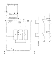
- the converter which is installed in an emergency lamp with fluorescent lamp to ignite the bulb, can be built as a flyback converter.
- On the FIG. 1 is such a converter drawn.
- the transistor T bipolar or mosfet
- the current flows from the battery B in the primary winding of the converter W.
- the diode D prevents the flow of current on the secondary side.
- the energy from the battery B is stored in the inductance of the primary winding.
- transistor T is blocked, the secondary voltage increases until the current in the secondary winding can flow.
- the diode D is blocked, and the energy can be stored again in the converter.
- Such a converter is well known and has been used for emergency lighting for more than 20 years.
- the current controller separates the ignition into two sequential operations, a startup phase and a normal phase, wherein the current controller adjusts the discharge current to a nominal value during the normal phase, and adjusts the discharge current to a higher value than the nominal value during the startup phase by adjusting the pulse width or the duty cycle, and, and the frequency keeps constant.
- the current controller alters the frequency without changing the last value of the duty cycle reached at the end of the starting phase.
- This change in frequency, as well as the change in the duty cycle is preferably carried out as a control, based on the discharge current.
- the discharge current can be measured for this purpose, or calculated from a measurement of the battery voltage.
- the required measuring device such as sensors, A / D converters, filters
- calculating means such as a microcontroller or an analog circuit
- the current determination and the determination of the control parameters of the PWM signal are combined in a single function, without explicitly determining the primary current. This function is called a control value determination means.
- the current determination means or the control value determination means are implemented by tabulated functions.
- the single-shot flyback converter which fires the fluorescent lamp in emergency mode, is thus controlled by a pulse width modulation (PWM) method.
- PWM pulse width modulation
- the frequency is kept constant and the battery discharge current is regulated to a higher value (eg twice) than the nominal value to ensure reliable ignition.
- the modulation of the PWM signal is changed.
- the start phase ie in the normal phase
- the current must be reduced and regulated at the nominal value.
- the duration of the on-state which was reached at the end of the starting phase, is kept constant.
- the regulation or control of the battery discharge current at the rated value takes place via a change of the PWM frequency. This is gradually reduced in the normal phase until the battery discharge current has reached the nominal value.
- This nominal value can be constant, as prescribed by certain standards for emergency lighting, or influenced by the battery voltage. so that the power, which is taken from the battery in emergency mode, is kept constant.
- the circuit preferably adapts automatically and adjusts itself to a duty cycle TON, which causes a reliable ignition.
- connection between the current measurement and filtering 1 and the current path only indicates the measurement schematically; For example, if the voltage across the shunt R is measured, of course, two electrical connections are required.
- the measurement of a sensor signal - voltage at the shunt R or at a Hall element, etc. - is preferably done with a multi-stage A / D converter or for example with two comparators whose thresholds are adjustable by the current measurement and filtering 1 and are constantly tracked.
- the current measurement and filtering 1 provides a filtered value for the primary current Ip, preferably an average value of the current varying over a period.
- the filtering can be done in a known manner by analog or digital means before respectively after the A / D conversion.
- the three control functions current measurement and filtering 1, PWM signal control 2 and current control 3 can be fully or partially realized with a microcontroller.
- the current measurement and filtering can be dispensed with in another preferred embodiment of the invention: As long as the single-ended flyback converter operates in the so-called “discontinuous mode", the current profile is as in the Figures 2 or 3 drawn, always starting at zero. That means that in the end the period stored in the converter has practically fallen to zero. Thus, the current can be calculated: Based on values of battery voltage, pulse width, pulse frequency and primary inductance P of the flyback converter, the microprocessor or microcontroller calculates the theoretical primary current Ip or discharge current of the battery without having to measure it.
- the calculation is replaced by a table of pre-calculated and stored values ("look-up table") stored in the memory of the microcontroller. Based on the measured battery voltage and the PWM frequency, the associated theoretical table value for the primary current Ip is fetched from the memory.
- look-up table a table of pre-calculated and stored values
- the associated theoretical table value for the primary current Ip is fetched from the memory.
- dependencies of certain parameters are expressed by a table and dependencies on other parameters by a calculation. The influence of the primary inductance P, which varies over time but varies depending on the device, is taken into account in the calculation of the table by measuring the primary inductance P after production.
- the influence of the battery voltage is neglected.
- the table has only two value pairs of f and TON: one for the start phase and one for the normal phase. The values of these parameters are a priori chosen to be in both Phases, regardless of the individual properties of the bulb safely ignites.
- the light source is ignited with a higher current.
- the battery discharge current can be regulated to three times the rated value for five seconds.
- the control is as follows: At the beginning the maximum frequency (eg 25kHz) and a TON initial value (eg 10us) are transmitted to the PWM signal control.
- the battery discharge current Ip is measured, and after a certain time delay, which depends on the frequency and the current measurement filtering, the TON value is changed stepwise to determine the difference between the actual value of Ip from the This measurement is repeated until the difference becomes small enough.
- another control method such as a P-controller or PI controller can be used.
- the battery discharge current Ip is thereby regulated at a higher value than during normal operation. Accordingly, the power transferred to the lamp should be sufficient to ensure proper ignition under all circumstances.
- the current Ip and the secondary voltage Vs should be as in the FIG. 2 look drawn.
- the TON value is a specific TON end value, which depends on the light source. Thus, this value can not be known in advance, because the electronic control can be used for a wide range of light sources. In addition, the TON-end value depends on the temperature and the age of the bulb.
- the battery discharge current Ip has a nominal value, which depends on the battery capacity and the desired operating time in emergency operation. In addition, this current is given by a corresponding standard for emergency lights. It is possible to easily influence this nominal value of the battery voltage. Thus, it is possible to realize a power control instead of a current control: According to the TON-end value, which was reached at the end of the starting phase, there is a certain TON-end energy, which is stored in the converter at each cycle. This TON-end energy is transmitted to the bulb every cycle, and with this TON-end energy, the bulb is ignited cleanly.
- the setpoint of the current control should be reduced to the nominal value.
- the TON-end value is maintained, so that the transmitted TON-end energy always suffices for a clean ignition.
- it is also possible to slightly vary the TON end value while still having the advantages of the invention.
- the value of TON in the normal phase may be slightly increased from the TON end value.
- the frequency is simply reduced. This control to the reduced frequency is gradual, similar to the current control in the starting phase.
- the TON value remains essentially constant, equal to the TON end value.
- the TON value is varied by no more than 15% or 10% or 5% around the TON end value, in a positive or in a negative direction.
Landscapes
- Business, Economics & Management (AREA)
- Emergency Management (AREA)
- Engineering & Computer Science (AREA)
- Power Engineering (AREA)
- Circuit Arrangements For Discharge Lamps (AREA)
- Dc-Dc Converters (AREA)
Claims (12)
- Circuit électronique d'allumage d'une lampe à fluorescence (L) alimentée par accumulateur, lequel circuit étant formé comme convertisseur de blocage à cadence unique doté d'un commutateur électronique, en particulier un transistor (T), et présentant les composants de commande suivants :- une commande (2) à signal en impulsions à largeur modulée (PWM) qui forme à l'aide de deux paramètres de commande, à savoir une fréquence (f) et une durée de branchement (TON) un signal PWM qui commande le commutateur électronique (T) du convertisseur de blocage,- une commande de courant (3) qui contrôle le courant (Ip) de décharge de la batterie (B) en déterminant les deux paramètres de commande (f, TON) du signal PWM et en les transmettant à la commande (2) à signal PWM,caractérisé en ce que
la commande de courant (3) divisant l'allumage en deux opérations successives, à savoir une phase de démarrage et une phase normale, la commande de courant (3) réglant le courant de décharge (Ip) à une valeur nominale pendant la phase normale et la commande de courant (3) réglant le courant de décharge (Ip) à une valeur supérieure à la valeur nominale pendant la phase de démarrage en définissant la largeur des impulsions ou durée de branchement (TON) tout en maintenant constante la fréquence (f),
pendant la phase normale, la commande de courant (3) modifie la fréquence (f) pour régler le courant (Ip) à la valeur nominale sans pour autant modifier considérablement la dernière valeur de la durée de branchement (TON) qui a été atteinte à la fin de la phase de démarrage. - Circuit électronique selon la revendication 1,
caractérisé en ce que pendant la phase normale, la commande de courant (3) ne modifie pas de plus de 15 % la dernière valeur de la durée de branchement (TON) qui a été atteinte à la fin de la phase de démarrage. - Circuit électronique selon la revendication 2,
présentant un moyen de détermination du courant qui détermine une valeur représentative du courant de décharge ou courant primaire (Ip), la commande de courant (3) adaptant au moins un des paramètres de commande (f, TON) du signal PWM à l'aide de cette valeur représentative. - Circuit électronique selon la revendication 3,
caractérisé en ce que le moyen de détermination du courant est un circuit (1) de mesure et de filtrage qui détermine une valeur de mesure du courant primaire (Ip) par une mesure suivie d'un filtrage. - Circuit électronique selon la revendication 4,
caractérisé en ce que le circuit (1) de mesure et de filtrage mesure et filtre le courant primaire (Ip) par l'intermédiaire d'une résistance (R) et d'un amplificateur, pour ainsi déterminer la valeur de la moyenne temporelle du courant primaire (Ip). - Circuit électronique selon la revendication 3,
caractérisé en ce que le moyen de détermination du courant est configuré pour déterminer une valeur théorique du courant primaire (Ip) à l'aide de la mesure de la tension de la batterie. - Circuit électronique selon la revendication 6,
caractérisé en ce que le moyen de détermination du courant est configuré pour calculer la valeur théorique du courant primaire (Ip) à l'aide de la mesure de la tension de la batterie, de l'inductance primaire (P) du convertisseur de blocage et des paramètres de commande (f, TON) du signal PWM. - Circuit électronique selon la revendication 6,
caractérisé en ce que le moyen de détermination du courant est configuré pour lire la valeur théorique du courant primaire (Ip) en mesurant la tension de la batterie dans un tableau conservé en mémoire. - Circuit électronique selon la revendication 1,
présentant un moyen de détermination d'une valeur de commande qui détermine les paramètres de commande (f, TON) du signal PWM à l'aide de la tension mesurée sur la batterie, en particulier par lecture des paramètres de commande (f, TON) pour la phase normale et pour la phase de démarrage dans des tableaux respectifs, en fonction de la tension de la batterie. - Lampe de secours contenant un circuit électronique d'allumage d'une lampe à fluorescence (L) selon la revendication 1.
- Procédé d'allumage d'une lampe à fluorescence (L) alimentée par accumulateur, la lampe présentant un convertisseur de blocage à cadence unique doté d'un commutateur électronique, en particulier un transistor (T), et présentant les étapes suivantes :- à l'aide de deux paramètres de commande, à savoir une fréquence (f) et une durée de branchement (TON), formation d'un signal PWM qui commande le commutateur électronique (T) par une commande (2) à signal PWM,- détermination des deux paramètres de commande (f, TON) du signal PWM et transmission des deux paramètres de commande (f, TON) à la commande (2) à signal PWM par une commande de courant (3) qui contrôle ainsi le courant de décharge (Ip) de la batterie,- division de l'allumage en deux opérations successives, à savoir une phase de démarrage et une phase normale, tandis que :- pendant la phase normale, le courant de décharge (Ip) est réglé à une valeur nominale par la commande de courant (3),- pendant la phase de démarrage, le courant de décharge (Ip) est réglé à une valeur plus élevée que la valeur nominale par la commande de courant (3) qui définit la largeur des impulsions ou durée de branchement (TON) et qui maintient constante la fréquence,caractérisé en ce que
pendant la phase normale, la commande de courant (3) modifie la fréquence (f) pour régler le courant (Ip) à la valeur nominale sans pour autant modifier considérablement la dernière valeur de la durée de branchement (TON) qui a été atteinte à la fin de la phase de démarrage. - Procédé selon la revendication 11, caractérisé en ce que pendant la phase normale, la dernière valeur de la durée de branchement (TON) qui a été atteinte à la fin de la phase de démarrage n'est pas modifiée de plus de 15 %.
Applications Claiming Priority (1)
| Application Number | Priority Date | Filing Date | Title |
|---|---|---|---|
| CH2082006 | 2006-02-09 |
Publications (2)
| Publication Number | Publication Date |
|---|---|
| EP1819207A1 EP1819207A1 (fr) | 2007-08-15 |
| EP1819207B1 true EP1819207B1 (fr) | 2009-09-16 |
Family
ID=36501853
Family Applications (1)
| Application Number | Title | Priority Date | Filing Date |
|---|---|---|---|
| EP07405034A Not-in-force EP1819207B1 (fr) | 2006-02-09 | 2007-02-06 | Procédé et dispositif destinés à l'allumage d'une lampe fluorescente |
Country Status (3)
| Country | Link |
|---|---|
| EP (1) | EP1819207B1 (fr) |
| AT (1) | ATE443428T1 (fr) |
| DE (1) | DE502007001515D1 (fr) |
Cited By (1)
| Publication number | Priority date | Publication date | Assignee | Title |
|---|---|---|---|---|
| DE102015204966A1 (de) | 2014-03-27 | 2015-10-01 | Huco Ag | Schaltungsanordnung zum Betreiben einer netzfreien, batteriebetriebenen, dimmbaren Leuchtstofflampen-Notlichtbeleuchtung |
Families Citing this family (1)
| Publication number | Priority date | Publication date | Assignee | Title |
|---|---|---|---|---|
| EP2418920B1 (fr) | 2010-07-21 | 2012-12-26 | polynom ag | Procédé et dispositif destinés à l'allumage d'une lampe fluorescente |
Family Cites Families (5)
| Publication number | Priority date | Publication date | Assignee | Title |
|---|---|---|---|---|
| DE9318071U1 (de) * | 1993-11-25 | 1995-03-23 | Patent-Treuhand-Gesellschaft für elektrische Glühlampen mbH, 81543 München | Schaltungsanordnung zum Betrieb einer Niederdruckentladungslampe an einer Niedervolt-Spannungsquelle |
| US6624599B1 (en) * | 2002-03-13 | 2003-09-23 | Fego Precision Industrial Co., Ltd. | Compact single-stage electronic ballast circuit for emergency lighting applications |
| JP4247048B2 (ja) * | 2003-06-05 | 2009-04-02 | 株式会社小糸製作所 | 直流電圧変換回路 |
| WO2005032219A1 (fr) * | 2003-09-26 | 2005-04-07 | Vicious Power Pty Ltd | Ameliorations apportees a une lampe a arc |
| WO2005039251A1 (fr) * | 2003-10-17 | 2005-04-28 | Vicious Power Pty Ltd | Regulation de puissance electronique pour lampes |
-
2007
- 2007-02-06 DE DE502007001515T patent/DE502007001515D1/de active Active
- 2007-02-06 AT AT07405034T patent/ATE443428T1/de active
- 2007-02-06 EP EP07405034A patent/EP1819207B1/fr not_active Not-in-force
Cited By (1)
| Publication number | Priority date | Publication date | Assignee | Title |
|---|---|---|---|---|
| DE102015204966A1 (de) | 2014-03-27 | 2015-10-01 | Huco Ag | Schaltungsanordnung zum Betreiben einer netzfreien, batteriebetriebenen, dimmbaren Leuchtstofflampen-Notlichtbeleuchtung |
Also Published As
| Publication number | Publication date |
|---|---|
| DE502007001515D1 (de) | 2009-10-29 |
| EP1819207A1 (fr) | 2007-08-15 |
| ATE443428T1 (de) | 2009-10-15 |
Similar Documents
| Publication | Publication Date | Title |
|---|---|---|
| EP2234240B1 (fr) | Circuit de commande de DEL | |
| EP2888800B1 (fr) | Appareil de lumière de secours | |
| DE4129557C2 (de) | Stromversorgungsschaltung für eine Gasentladungslampe in einem Fahrzeug | |
| AT14505U1 (de) | Verfahren und Vorrichtung zur Datenübertragung über eine Lastleitung und Beleuchtungssystem | |
| EP2438669A1 (fr) | Circuit électronique permettant de convertir un éclairage sur secteur en un éclairage de secours | |
| DE2009911C3 (de) | Ladegerät für Bleibatterien | |
| EP2189046A1 (fr) | Commande de la température de couleur des flasheuses | |
| DE112009002495T5 (de) | Leuchtvorrichtung für Fahrzeuglichtquelle | |
| EP1819207A1 (fr) | Procédé et dispositif destinés à l'allumage d'une lampe fluorescente | |
| EP2564674B1 (fr) | Procédé et circuit de commande pour la mise en marche d'une lampe à décharge gazeuse | |
| EP3393207B1 (fr) | Régulateur de commutation destiné au fonctionnement de moyens lumineux à suppression de luminescence résiduelle | |
| EP2777364B1 (fr) | Procédé de fonctionnement d'au moins une del par vibrations | |
| EP2418920B1 (fr) | Procédé et dispositif destinés à l'allumage d'une lampe fluorescente | |
| AT14557U1 (de) | Getaktete Sperrwandlerschaltung | |
| EP3791692B1 (fr) | Circuit convertisseur à transfert indirect synchrone pour faire fonctionner une section de moyens d'éclairage | |
| DE102011081211B4 (de) | Schaltungsanordnung und Verfahren zum alternativen Betreiben entweder einer Hochdruckentladungslampe oder mindestens einer Halbleiterlichtquellenlampe | |
| EP3439159A1 (fr) | Réduction de fluctuations de flux lumineux dans une commande de valeur seuil d'un convertisseur cadencé activement | |
| WO2016041567A1 (fr) | Ballast électronique et procédé de commande d'une charge | |
| DE202004005383U1 (de) | Scheinwerfer |
Legal Events
| Date | Code | Title | Description |
|---|---|---|---|
| PUAI | Public reference made under article 153(3) epc to a published international application that has entered the european phase |
Free format text: ORIGINAL CODE: 0009012 |
|
| AK | Designated contracting states |
Kind code of ref document: A1 Designated state(s): AT BE BG CH CY CZ DE DK EE ES FI FR GB GR HU IE IS IT LI LT LU LV MC NL PL PT RO SE SI SK TR |
|
| AX | Request for extension of the european patent |
Extension state: AL BA HR MK YU |
|
| 17P | Request for examination filed |
Effective date: 20080206 |
|
| AKX | Designation fees paid |
Designated state(s): AT BE BG CH CY CZ DE DK EE ES FI FR GB GR HU IE IS IT LI LT LU LV MC NL PL PT RO SE SI SK TR |
|
| GRAP | Despatch of communication of intention to grant a patent |
Free format text: ORIGINAL CODE: EPIDOSNIGR1 |
|
| GRAS | Grant fee paid |
Free format text: ORIGINAL CODE: EPIDOSNIGR3 |
|
| GRAA | (expected) grant |
Free format text: ORIGINAL CODE: 0009210 |
|
| AK | Designated contracting states |
Kind code of ref document: B1 Designated state(s): AT BE BG CH CY CZ DE DK EE ES FI FR GB GR HU IE IS IT LI LT LU LV MC NL PL PT RO SE SI SK TR |
|
| REG | Reference to a national code |
Ref country code: GB Ref legal event code: FG4D Free format text: NOT ENGLISH |
|
| REG | Reference to a national code |
Ref country code: CH Ref legal event code: EP |
|
| REG | Reference to a national code |
Ref country code: IE Ref legal event code: FG4D |
|
| REF | Corresponds to: |
Ref document number: 502007001515 Country of ref document: DE Date of ref document: 20091029 Kind code of ref document: P |
|
| REG | Reference to a national code |
Ref country code: CH Ref legal event code: NV Representative=s name: FREI PATENTANWALTSBUERO AG |
|
| PG25 | Lapsed in a contracting state [announced via postgrant information from national office to epo] |
Ref country code: LT Free format text: LAPSE BECAUSE OF FAILURE TO SUBMIT A TRANSLATION OF THE DESCRIPTION OR TO PAY THE FEE WITHIN THE PRESCRIBED TIME-LIMIT Effective date: 20090916 Ref country code: SE Free format text: LAPSE BECAUSE OF FAILURE TO SUBMIT A TRANSLATION OF THE DESCRIPTION OR TO PAY THE FEE WITHIN THE PRESCRIBED TIME-LIMIT Effective date: 20090916 Ref country code: FI Free format text: LAPSE BECAUSE OF FAILURE TO SUBMIT A TRANSLATION OF THE DESCRIPTION OR TO PAY THE FEE WITHIN THE PRESCRIBED TIME-LIMIT Effective date: 20090916 |
|
| LTIE | Lt: invalidation of european patent or patent extension |
Effective date: 20090916 |
|
| PG25 | Lapsed in a contracting state [announced via postgrant information from national office to epo] |
Ref country code: LV Free format text: LAPSE BECAUSE OF FAILURE TO SUBMIT A TRANSLATION OF THE DESCRIPTION OR TO PAY THE FEE WITHIN THE PRESCRIBED TIME-LIMIT Effective date: 20090916 Ref country code: PL Free format text: LAPSE BECAUSE OF FAILURE TO SUBMIT A TRANSLATION OF THE DESCRIPTION OR TO PAY THE FEE WITHIN THE PRESCRIBED TIME-LIMIT Effective date: 20090916 Ref country code: SI Free format text: LAPSE BECAUSE OF FAILURE TO SUBMIT A TRANSLATION OF THE DESCRIPTION OR TO PAY THE FEE WITHIN THE PRESCRIBED TIME-LIMIT Effective date: 20090916 |
|
| PG25 | Lapsed in a contracting state [announced via postgrant information from national office to epo] |
Ref country code: CY Free format text: LAPSE BECAUSE OF FAILURE TO SUBMIT A TRANSLATION OF THE DESCRIPTION OR TO PAY THE FEE WITHIN THE PRESCRIBED TIME-LIMIT Effective date: 20090916 |
|
| REG | Reference to a national code |
Ref country code: IE Ref legal event code: FD4D |
|
| PG25 | Lapsed in a contracting state [announced via postgrant information from national office to epo] |
Ref country code: CZ Free format text: LAPSE BECAUSE OF FAILURE TO SUBMIT A TRANSLATION OF THE DESCRIPTION OR TO PAY THE FEE WITHIN THE PRESCRIBED TIME-LIMIT Effective date: 20090916 Ref country code: EE Free format text: LAPSE BECAUSE OF FAILURE TO SUBMIT A TRANSLATION OF THE DESCRIPTION OR TO PAY THE FEE WITHIN THE PRESCRIBED TIME-LIMIT Effective date: 20090916 Ref country code: RO Free format text: LAPSE BECAUSE OF FAILURE TO SUBMIT A TRANSLATION OF THE DESCRIPTION OR TO PAY THE FEE WITHIN THE PRESCRIBED TIME-LIMIT Effective date: 20090916 Ref country code: ES Free format text: LAPSE BECAUSE OF FAILURE TO SUBMIT A TRANSLATION OF THE DESCRIPTION OR TO PAY THE FEE WITHIN THE PRESCRIBED TIME-LIMIT Effective date: 20091227 Ref country code: PT Free format text: LAPSE BECAUSE OF FAILURE TO SUBMIT A TRANSLATION OF THE DESCRIPTION OR TO PAY THE FEE WITHIN THE PRESCRIBED TIME-LIMIT Effective date: 20100118 Ref country code: IS Free format text: LAPSE BECAUSE OF FAILURE TO SUBMIT A TRANSLATION OF THE DESCRIPTION OR TO PAY THE FEE WITHIN THE PRESCRIBED TIME-LIMIT Effective date: 20100116 Ref country code: IE Free format text: LAPSE BECAUSE OF FAILURE TO SUBMIT A TRANSLATION OF THE DESCRIPTION OR TO PAY THE FEE WITHIN THE PRESCRIBED TIME-LIMIT Effective date: 20090916 |
|
| PG25 | Lapsed in a contracting state [announced via postgrant information from national office to epo] |
Ref country code: SK Free format text: LAPSE BECAUSE OF FAILURE TO SUBMIT A TRANSLATION OF THE DESCRIPTION OR TO PAY THE FEE WITHIN THE PRESCRIBED TIME-LIMIT Effective date: 20090916 |
|
| PLBE | No opposition filed within time limit |
Free format text: ORIGINAL CODE: 0009261 |
|
| STAA | Information on the status of an ep patent application or granted ep patent |
Free format text: STATUS: NO OPPOSITION FILED WITHIN TIME LIMIT |
|
| PG25 | Lapsed in a contracting state [announced via postgrant information from national office to epo] |
Ref country code: DK Free format text: LAPSE BECAUSE OF FAILURE TO SUBMIT A TRANSLATION OF THE DESCRIPTION OR TO PAY THE FEE WITHIN THE PRESCRIBED TIME-LIMIT Effective date: 20090916 |
|
| 26N | No opposition filed |
Effective date: 20100617 |
|
| PG25 | Lapsed in a contracting state [announced via postgrant information from national office to epo] |
Ref country code: MC Free format text: LAPSE BECAUSE OF NON-PAYMENT OF DUE FEES Effective date: 20100301 Ref country code: GR Free format text: LAPSE BECAUSE OF FAILURE TO SUBMIT A TRANSLATION OF THE DESCRIPTION OR TO PAY THE FEE WITHIN THE PRESCRIBED TIME-LIMIT Effective date: 20091217 |
|
| REG | Reference to a national code |
Ref country code: FR Ref legal event code: ST Effective date: 20101029 |
|
| PG25 | Lapsed in a contracting state [announced via postgrant information from national office to epo] |
Ref country code: FR Free format text: LAPSE BECAUSE OF NON-PAYMENT OF DUE FEES Effective date: 20100301 |
|
| PG25 | Lapsed in a contracting state [announced via postgrant information from national office to epo] |
Ref country code: IT Free format text: LAPSE BECAUSE OF FAILURE TO SUBMIT A TRANSLATION OF THE DESCRIPTION OR TO PAY THE FEE WITHIN THE PRESCRIBED TIME-LIMIT Effective date: 20090916 |
|
| REG | Reference to a national code |
Ref country code: CH Ref legal event code: PFA Owner name: POLYNOM AG Free format text: SANDER ELEKTRONIK AG#STAUSEESTRASSE 73#5314 KLEINDOETTINGEN (CH) -TRANSFER TO- POLYNOM AG#STAUSEESTRASSE 73#5314 KLEINDOETTINGEN (CH) |
|
| REG | Reference to a national code |
Ref country code: NL Ref legal event code: TD Effective date: 20110708 |
|
| REG | Reference to a national code |
Ref country code: DE Ref legal event code: R082 Ref document number: 502007001515 Country of ref document: DE Representative=s name: OSTERTAG & PARTNER, PATENTANWAELTE, DE |
|
| REG | Reference to a national code |
Ref country code: DE Ref legal event code: R081 Ref document number: 502007001515 Country of ref document: DE Owner name: POLYNOM AG, CH Free format text: FORMER OWNER: SANDER ELEKTRONIK AG, KLEINDOETTINGEN, CH Effective date: 20110727 Ref country code: DE Ref legal event code: R082 Ref document number: 502007001515 Country of ref document: DE Representative=s name: OSTERTAG & PARTNER, PATENTANWAELTE MBB, DE Effective date: 20110727 Ref country code: DE Ref legal event code: R082 Ref document number: 502007001515 Country of ref document: DE Representative=s name: OSTERTAG & PARTNER, PATENTANWAELTE, DE Effective date: 20110727 |
|
| PG25 | Lapsed in a contracting state [announced via postgrant information from national office to epo] |
Ref country code: BG Free format text: LAPSE BECAUSE OF FAILURE TO SUBMIT A TRANSLATION OF THE DESCRIPTION OR TO PAY THE FEE WITHIN THE PRESCRIBED TIME-LIMIT Effective date: 20090916 Ref country code: LU Free format text: LAPSE BECAUSE OF NON-PAYMENT OF DUE FEES Effective date: 20100206 Ref country code: HU Free format text: LAPSE BECAUSE OF FAILURE TO SUBMIT A TRANSLATION OF THE DESCRIPTION OR TO PAY THE FEE WITHIN THE PRESCRIBED TIME-LIMIT Effective date: 20100317 |
|
| PG25 | Lapsed in a contracting state [announced via postgrant information from national office to epo] |
Ref country code: TR Free format text: LAPSE BECAUSE OF FAILURE TO SUBMIT A TRANSLATION OF THE DESCRIPTION OR TO PAY THE FEE WITHIN THE PRESCRIBED TIME-LIMIT Effective date: 20090916 |
|
| REG | Reference to a national code |
Ref country code: AT Ref legal event code: MM01 Ref document number: 443428 Country of ref document: AT Kind code of ref document: T Effective date: 20120206 |
|
| PG25 | Lapsed in a contracting state [announced via postgrant information from national office to epo] |
Ref country code: AT Free format text: LAPSE BECAUSE OF NON-PAYMENT OF DUE FEES Effective date: 20120206 |
|
| PGFP | Annual fee paid to national office [announced via postgrant information from national office to epo] |
Ref country code: NL Payment date: 20150218 Year of fee payment: 9 |
|
| PGFP | Annual fee paid to national office [announced via postgrant information from national office to epo] |
Ref country code: CH Payment date: 20150209 Year of fee payment: 9 Ref country code: DE Payment date: 20150219 Year of fee payment: 9 |
|
| PGFP | Annual fee paid to national office [announced via postgrant information from national office to epo] |
Ref country code: GB Payment date: 20150218 Year of fee payment: 9 |
|
| PGFP | Annual fee paid to national office [announced via postgrant information from national office to epo] |
Ref country code: BE Payment date: 20150218 Year of fee payment: 9 |
|
| PG25 | Lapsed in a contracting state [announced via postgrant information from national office to epo] |
Ref country code: BE Free format text: LAPSE BECAUSE OF NON-PAYMENT OF DUE FEES Effective date: 20160229 |
|
| REG | Reference to a national code |
Ref country code: DE Ref legal event code: R119 Ref document number: 502007001515 Country of ref document: DE |
|
| REG | Reference to a national code |
Ref country code: CH Ref legal event code: PL |
|
| GBPC | Gb: european patent ceased through non-payment of renewal fee |
Effective date: 20160206 |
|
| PG25 | Lapsed in a contracting state [announced via postgrant information from national office to epo] |
Ref country code: LI Free format text: LAPSE BECAUSE OF NON-PAYMENT OF DUE FEES Effective date: 20160229 Ref country code: CH Free format text: LAPSE BECAUSE OF NON-PAYMENT OF DUE FEES Effective date: 20160229 |
|
| REG | Reference to a national code |
Ref country code: NL Ref legal event code: MM Effective date: 20160301 |
|
| PG25 | Lapsed in a contracting state [announced via postgrant information from national office to epo] |
Ref country code: DE Free format text: LAPSE BECAUSE OF NON-PAYMENT OF DUE FEES Effective date: 20160901 Ref country code: GB Free format text: LAPSE BECAUSE OF NON-PAYMENT OF DUE FEES Effective date: 20160206 Ref country code: NL Free format text: LAPSE BECAUSE OF NON-PAYMENT OF DUE FEES Effective date: 20160301 |