EP1819902B1 - Porte-outil - Google Patents
Porte-outil Download PDFInfo
- Publication number
- EP1819902B1 EP1819902B1 EP05798097.1A EP05798097A EP1819902B1 EP 1819902 B1 EP1819902 B1 EP 1819902B1 EP 05798097 A EP05798097 A EP 05798097A EP 1819902 B1 EP1819902 B1 EP 1819902B1
- Authority
- EP
- European Patent Office
- Prior art keywords
- chisel
- connecting section
- base part
- chisel holder
- section
- Prior art date
- Legal status (The legal status is an assumption and is not a legal conclusion. Google has not performed a legal analysis and makes no representation as to the accuracy of the status listed.)
- Expired - Lifetime
Links
Images

Classifications
-
- E—FIXED CONSTRUCTIONS
- E21—EARTH OR ROCK DRILLING; MINING
- E21C—MINING OR QUARRYING
- E21C35/00—Details of, or accessories for, machines for slitting or completely freeing the mineral from the seam, not provided for in groups E21C25/00 - E21C33/00, E21C37/00 or E21C39/00
- E21C35/18—Mining picks; Holders therefor
Definitions
- the invention relates to a bit holder for a road milling machine or the like with a base part, which carries a holding lug, wherein the holding lug has a chisel receptacle and wherein in the tool feed direction of the chisel holder before the holding lug, a projection is connected to the base part.
- a chisel holder is known which has a holding approach.
- In the holding approach designed as a chisel receiving cylindrical bore is introduced.
- a projection is arranged in the feed direction before the holding lug. This is connected via a connecting portion with the holding approach.
- the retaining lug has a bearing surface.
- a chisel holder which has a holding approach with a chisel holder.
- the holding lug is provided with wear marks that clearly show the state of wear of the chisel holder.
- a similar chisel holder is also from the DE 20 2005 001 311 U1 known.
- DE 101 42 438 A1 shows a chisel holder with a holding lug, in which a chisel holder is introduced.
- the bit holder is drilled in a cylindrical part of the retaining lug so that an annular support surface rotates about the bore entry of the bit holder.
- On this support surface a chisel head is supported with the interposition of a wear protection disc.
- the wear protection disc covers the support surface. During operation, the bit head rotates on the wear plate.
- Another chisel holder is from the DE 43 22 401 C2 known.
- the bit holder is provided with a plug-in approach, with which he is held interchangeable in a socket of a base body.
- the base body is on the outside circumference attached to a Fräswalzenrohres.
- the plug attachment of the chisel holder is connected in one piece to a base part.
- the base part carries on the side facing away from the plug approach a holding approach.
- the holding approach is provided with a bore into which a shank bit can be used in a known manner.
- the shows DE 37 01 905 C1 an example of a possible mounting situation.
- chisel holders are used on road milling machines, but also on earthworking machines, such as soil stabilizers, mining machines, etc.
- earthworking machines such as soil stabilizers, mining machines, etc.
- the power consumption of the machine changes. It turns out that coatings built up in layers, which tend to form flake chips during cutting, present a high resistance to the tool. For example, such chip forms when dividing asphalt surfaces, in which there is an insufficient bond between the top layer (usually about 4 cm thick) and the binder layer.
- the bit holder has a base part, in which a bore formed as a bit holder is introduced.
- the base member has a projecting end portion which is frusto-conical in shape from a circumferential wall.
- a round shank chisel can be inserted with its chisel shank.
- a chisel head is formed, which rests with a bearing surface on an annular circumferential support surface of the end portion.
- the bit holder rotates in the bit holder.
- Another chisel holder is in DE 298 05 007 U1 disclosed.
- the base part has a chip breaker designed as a connecting portion which is integrally formed on the base part and extending from the holding approach at least partially over the projection.
- the end portion of the retaining lug has a drill bit holder formed as a bore, that the end portion has an annularly around the central longitudinal axis of the bit holder rotating support surface, that the support surface radially outward lying to the dimensional limitations of a cylindrical portion extends the end portion and that the connecting portion is recessed in the axial direction relative to the support surface is attached to the holding lug.
- the cylindrical portion of the holding approach forms a wear zone, as they are in principle in the DE 199 02 766.8-24 is described.
- the head of a shank bit is supported with the interposition of a wear protection disc.
- the wear protection disc extends at least up to the dimensional limitations of the support surface. This creates a wear system.
- the wear protection disc rotates on the support surface and continuously cuts off the cylindrical area. Due to the set-back arrangement of Connecting portion of the holding approach is stabilized, but does not affect this wear system.
- the resulting chips especially larger clods can be effectively divided.
- the cutting resistance of the bit holder the milled material is reduced contrary, resulting in a reduction in power consumption.
- connection of the holding approach to the projection by means of the connecting portion brings improved tool rigidity. This has a positive effect especially in the case of exposed retaining lugs and / or projections and leads to an increase in the service life.
- the connecting portion forms a web portion, that the holding lug has an over the base portion projecting end portion and that the transverse to the feed direction web width is smaller than the dimension of the end portion in this direction.
- the connecting section extends in the tool feed direction. In this way, a cutting geometry is created, which opposes the milled material low penetration resistance.
- the connecting section has chip guiding surfaces on both sides of the web section, which diverge starting from the web section in the direction of the base part and the connecting section is connected to the retaining shoulder via hollow-throat-shaped transition sections.
- An optimization of the cutting geometry of the chisel holder results from the fact that the base part in the region of the projection is bounded laterally by two inclined surfaces which are arrow-shaped in the tool feed direction and in that the connecting portion and the inclined surface leak in a front end region of the projection.
- the front earth area forms a tapered section which allows a good chip removal, especially with coarse chip milling ground.
- the service life of the chisel holder can be optimized in that the connecting portion is hardened and / or that at least one hard material element is applied to the connecting portion.
- a hard material element for example, a hard metal can be used.
- a good chip-breaking geometry results from the fact that the connecting portion has a conical or rounded cutting edge shape.
- the Fig. 1 shows a chisel holder with a base part 10.
- the base part 10 has a support member with a downwardly facing support surface 11.
- the support member is in the feed direction in a projection 15 on.
- the projection 15 is at an angle to the support member.
- a downwardly projecting tab 12 is integrally formed on the base part 10. With the plug neck 12 of the bit holder can be inserted into a socket of a base body 50. In the plug-in receptacle 12, the plug-in projection 12 can then be tensioned.
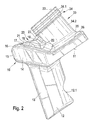
- Front centering surfaces 13 and a in Fig. 2 shown back clamping surface 12.1 of the plug-in projection 12 serve as a support.
- the bit holder In the assembled state, the bit holder is supported by its support surface 11 on a mating surface of the base body 50.
- the projection 15 covers a shoulder 51 of the base body 50 and thus protects it from the wear attack of the removed milled material.
- a holding lug 30 is integrally formed via a connecting portion 35.
- the connecting portion 35 may also have a frusto-conical or hollow throat-shaped geometry. At its end facing away from the connecting portion 35 of the holding lug 30 runs in a projecting cylindrical end portion 34 from.
- wear marks 34.1 In this end portion 34 two concentric about a introduced into the holding lug 30 bore (bit holder 31) rotating wear marks 34.1 are screwed.
- the wear marks 34.1 thus form groove-shaped recesses, which are arranged behind a cylindrical end portion 34 final support surface 33.
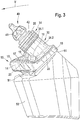
- a round shank chisel 40 can be inserted with its shank portion in the bit holder 31.
- the round shank chisel then has on the shank portion a chisel head 41 which carries a chisel tip made of hard material.
- the bit head 41 is supported by the interposition of a wear plate 42 on the support surface 33 of the retaining lug 30 from.
- FIG. 2 clearly shows the holding lug 30 forms between the cylindrical end portion 34 and the rounding portion 35 has a central connecting part 34.2. This is connected by means of a connecting portion 20 to the projection 15 in one piece.
- the connecting portion 20 extends starting from the connecting part 34.2 in the tool feed direction. It has a flattened web portion 21, which merges via inclined rake surfaces 22 in the side surfaces 19 of the projection 15. The connecting portion 20 continuously runs out toward a front end portion of the projection 15.
- Two oblique surfaces 14 laterally delimiting the projection 15 likewise run out in this area, so that an arrow-shaped contour results with the connecting section 20 and the inclined surfaces 14.
- the projection 15 is closed in the end region by means of a rounding transition 16.
- the inclined surfaces 14 adjoin the side surfaces 19 via rounding transitions 17.
- the connecting portion 20 is connected to the holding lug 30 for reasons of voltage optimization on the one hand and for improved chip removal on the other hand with rounded transition sections 18,23.
Landscapes
- Engineering & Computer Science (AREA)
- Mining & Mineral Resources (AREA)
- Mechanical Engineering (AREA)
- Life Sciences & Earth Sciences (AREA)
- General Life Sciences & Earth Sciences (AREA)
- Geochemistry & Mineralogy (AREA)
- Geology (AREA)
- Drilling And Exploitation, And Mining Machines And Methods (AREA)
- Road Repair (AREA)
- Percussive Tools And Related Accessories (AREA)
Claims (8)
- Porte-outil pour fraiseuse à froid ou machine de ce type, comportant une embase (10) qui porte une pièce de maintien (30), ladite pièce de maintien (30) présentant un logement pour outil (31), un épaulement (15) étant rapporté sur l'embase (10) dans le sens d'avance du porte-outil en amont de la pièce de maintien (30), une section terminale (34) de la pièce de maintien (30) présentant un logement pour outil (31) sous forme d'un alésage, ladite pièce de maintien (30) présentant une section terminale (34) en porte à faux au-dessus de l'embase (10), la section terminale (34) présentant une surface d'appui (33) annulaire autour de l'axe longitudinal central du logement pour outil (31),
la surface d'appui (33) s'étendant de manière radiale à l'extérieur jusqu'aux limites dimensionnelles d'une zone cylindrique de la section terminale (34),
caractérisé en ce que
l'embase (10) présente une section d'assemblage (20) façonnée comme brise-copeaux et moulée contre l'embase (10) et qui s'étend de la pièce de maintien (30) au-delà de l'épaulement (15) au moins partiellement, en ce que la section d'assemblage (20) soit raccordée à la pièce de maintien (30) en retrait par rapport à la surface d'appui (33) dans le sens de l'axe longitudinal central du logement pour outil,
en ce que la section d'assemblage (20) forme une section d'entretoise (21),
et en ce que la largeur de l'entretoise est plus petite perpendiculairement au dispositif d'avance que la taille de la section terminale (34) dans ce sens. - Porte-outil selon la revendication 1,
caractérisé en ce que
la section d'assemblage (20) s'étend dans le sens de l'avance de l'outil. - Porte-outil selon une des revendications 1 ou 2,
caractérisé en ce que
la section d'assemblage (20) présente des surfaces déflectrices (22) des deux côtés de la section d'entretoise (21), lesquelles partant de la section d'entretoise (21) divergent en direction de l'embase (10). - Porte-outil selon les revendications 1 à 3,
caractérisé en ce que
la section d'assemblage (20) est raccordée à la pièce de maintien (30) par l'intermédiaire de sections transitoires (18) concaves. - Porte-outil selon une des revendications 1 à 4,
caractérisé en ce que
l'embase (10) est délimitée latéralement par deux surfaces obliques (14) au niveau de l'épaulement (15), lesquelles sont disposées en forme de flèche l'une par rapport à l'autre dans le sens d'avance de l'outil et
en ce que la section d'assemblage (20) et la surface oblique (14) dans une zone terminale en façade de l'épaulement (15). - Porte-outil selon une des revendications 1 à 5,
caractérisé en ce que
la section d'assemblage (20) est trempée. - Porte-outil selon une des revendications 1 à 6,
caractérisé en ce que
sur la section d'assemblage (20) est placé au moins un élément en matériau dur. - Porte-outil selon une des revendications 1 à 7,
caractérisé en ce que
la section d'assemblage (20) présente une forme de forme de taillant conique ou arrondie.
Applications Claiming Priority (2)
| Application Number | Priority Date | Filing Date | Title |
|---|---|---|---|
| DE102004057302A DE102004057302B4 (de) | 2004-11-26 | 2004-11-26 | Meißelhalter |
| PCT/EP2005/010865 WO2006056269A1 (fr) | 2004-11-26 | 2005-10-08 | Porte-outil |
Publications (2)
| Publication Number | Publication Date |
|---|---|
| EP1819902A1 EP1819902A1 (fr) | 2007-08-22 |
| EP1819902B1 true EP1819902B1 (fr) | 2018-12-12 |
Family
ID=35457998
Family Applications (1)
| Application Number | Title | Priority Date | Filing Date |
|---|---|---|---|
| EP05798097.1A Expired - Lifetime EP1819902B1 (fr) | 2004-11-26 | 2005-10-08 | Porte-outil |
Country Status (11)
| Country | Link |
|---|---|
| US (1) | US7300115B2 (fr) |
| EP (1) | EP1819902B1 (fr) |
| JP (1) | JP4728341B2 (fr) |
| KR (1) | KR100915603B1 (fr) |
| CN (1) | CN101175895B (fr) |
| AU (1) | AU2005309142B2 (fr) |
| BR (1) | BRPI0518252B1 (fr) |
| DE (1) | DE102004057302B4 (fr) |
| RU (1) | RU2347907C1 (fr) |
| TR (1) | TR201900655T4 (fr) |
| WO (1) | WO2006056269A1 (fr) |
Cited By (3)
| Publication number | Priority date | Publication date | Assignee | Title |
|---|---|---|---|---|
| WO2025233217A1 (fr) * | 2024-05-06 | 2025-11-13 | Wirtgen Gmbh | Porte-burin |
| WO2025233214A1 (fr) * | 2024-05-06 | 2025-11-13 | Wirtgen Gmbh | Support de trépan |
| WO2025233213A1 (fr) * | 2024-05-06 | 2025-11-13 | Wirtgen Gmbh | Support de burin |
Families Citing this family (50)
| Publication number | Priority date | Publication date | Assignee | Title |
|---|---|---|---|---|
| USD574689S1 (en) * | 2006-03-10 | 2008-08-12 | Wirtgen Gmbh | Chisel holder |
| USD585259S1 (en) * | 2006-03-10 | 2009-01-27 | Wirtgen Bmbh | Chisel holder |
| USD575610S1 (en) * | 2006-03-10 | 2008-08-26 | Wirtgen Gmbh | Chisel holder |
| US7380887B2 (en) * | 2006-04-13 | 2008-06-03 | Keystone Engineering & Manufacturing Corp. | Tool holder |
| EP2048323B1 (fr) | 2007-10-11 | 2010-07-28 | Everpads Co., Ltd. | Dispositif de manipulation d'outil |
| DE102008045825B3 (de) * | 2008-09-05 | 2010-05-27 | Wirtgen Gmbh | Meißelhalter für eine Schrämmaschine, Straßenfräse, Suface-Miner oder dergleichen |
| US8523290B2 (en) * | 2009-04-10 | 2013-09-03 | Kennametal Inc. | Rotatable cutting tool-tool holder-base assembly |
| DE102009059189A1 (de) | 2009-12-17 | 2011-06-22 | Wirtgen GmbH, 53578 | Meißelhalter und Basisteil zur Aufnahme eines Meißelhalters |
| DE102009059188A1 (de) * | 2009-12-17 | 2011-06-22 | Wirtgen GmbH, 53578 | Meißelhalter und Basisteil |
| USD632703S1 (en) * | 2010-01-07 | 2011-02-15 | Wirtgen Gmbh | Kicker plate |
| USD624940S1 (en) * | 2010-01-07 | 2010-10-05 | Wirtgen Gmbh | Kicker plate |
| USD628602S1 (en) * | 2010-01-07 | 2010-12-07 | Wirtgen Gmbh | Kicker plate |
| US9028009B2 (en) | 2010-01-20 | 2015-05-12 | Element Six Gmbh | Pick tool and method for making same |
| GB201000869D0 (en) * | 2010-01-20 | 2010-03-10 | Element Six Holding Gmbh | Superhard pick tool and method for making same |
| US8313153B2 (en) * | 2010-03-24 | 2012-11-20 | Kennametal Inc. | Rotatable cutting tool and tool holder assembly |
| USD638453S1 (en) * | 2010-11-10 | 2011-05-24 | Wirtgen Gmbh | Bit holder |
| RU2567256C2 (ru) * | 2010-12-03 | 2015-11-10 | Виртген Гмбх | Резцедержатель и система резцедержателя с резцедержателем и корпусом |
| TWI480447B (zh) * | 2010-12-03 | 2015-04-11 | Wirtgen Gmbh | Turret (b) |
| US9163502B2 (en) | 2010-12-03 | 2015-10-20 | Wirtgen Gmbh | Chisel holder, and chisel holder system comprising a chisel holder and a base part |
| DE102010061019A1 (de) | 2010-12-03 | 2012-06-06 | Betek Gmbh & Co. Kg | Meißelhalter und Werkzeugunterteil für einen Meißelhalter |
| KR101788266B1 (ko) | 2010-12-03 | 2017-10-19 | 비르트겐 게엠베하 | 치즐 홀더 |
| GB201103096D0 (en) | 2011-02-23 | 2011-04-06 | Element Six Holding Gmbh | Insert and degradation assembly |
| USD667855S1 (en) * | 2011-04-11 | 2012-09-25 | Betek Gmbh & Co. Kg | Base for a chisel holder |
| USD667856S1 (en) * | 2011-04-11 | 2012-09-25 | Betek Gmbh & Co. Kg | Chisel holder |
| DE102011051525A1 (de) | 2011-07-04 | 2013-01-10 | Wirtgen Gmbh | Meißelhalter für eine Bodenbearbeitungsmaschine |
| PL2543815T4 (pl) | 2011-07-04 | 2020-06-15 | Wirtgen Gmbh | Imak nożowy i układ imaka nożowego z imakiem nożowym i częścią podstawową |
| USD671578S1 (en) * | 2011-07-04 | 2012-11-27 | Wirtgen Gmbh | Chisel holder |
| GB201113013D0 (en) | 2011-07-28 | 2011-09-14 | Element Six Abrasive Sa | Tip for a pick tool |
| USD669505S1 (en) * | 2011-11-23 | 2012-10-23 | Wirtgen Gmbh | Chisel holder bar |
| USD677285S1 (en) * | 2011-11-23 | 2013-03-05 | Wirtgen Gmbh | Chisel holder bar |
| USD688282S1 (en) * | 2012-02-09 | 2013-08-20 | Frank Friedrich Lachmann | Tool |
| GB201202533D0 (en) * | 2012-02-14 | 2012-03-28 | Element Six Gmbh | Pick tool and method of using same |
| USD680560S1 (en) * | 2012-07-31 | 2013-04-23 | Caterpillar Paving Products Inc. | Deflector for paving apparatus |
| USD681069S1 (en) * | 2012-07-31 | 2013-04-30 | Caterpillar Paving Products Inc. | Mounting block for paving apparatus |
| USD692037S1 (en) * | 2012-12-05 | 2013-10-22 | Wirtgen Gmbh | Chisel holder |
| US9441482B2 (en) | 2013-01-30 | 2016-09-13 | Novatek Ip, Llc | Hammer element on a degradation pick |
| USD692040S1 (en) * | 2013-04-12 | 2013-10-22 | Wirtgen Gmbh | Chisel holder |
| USD692039S1 (en) * | 2013-04-12 | 2013-10-22 | Wirtgen Gmbh | Chisel holder |
| RU2666906C2 (ru) * | 2013-06-18 | 2018-09-13 | Эско Корпорейшн | Резец для добычи полезных ископаемых, резцедержатель и их комбинация |
| USD707736S1 (en) | 2013-06-19 | 2014-06-24 | Bernd Heinrich Ries | Chisel holder |
| USD736283S1 (en) * | 2013-06-19 | 2015-08-11 | Element Six Gmbh | Chisel holder |
| USD711442S1 (en) * | 2013-07-15 | 2014-08-19 | Wirtgen Gmbh | Chisel holder |
| RU2602435C1 (ru) * | 2015-10-07 | 2016-11-20 | федеральное государственное бюджетное образовательное учреждение высшего образования "Пермский национальный исследовательский политехнический университет" | Устройство для крепления резца на исполнительном органе машины |
| JP1572680S (fr) | 2016-02-22 | 2017-03-27 | ||
| DE102016108808A1 (de) | 2016-05-12 | 2017-11-16 | Betek Gmbh & Co. Kg | Meißel mit einem Stützelement mit einem Zentrieransatz |
| DE102016224606B4 (de) * | 2016-12-09 | 2021-01-07 | Wirtgen Gmbh | Vorrichtung zur spanenden Bearbeitung von verschleißbelasteten Meißelhaltern von Straßenfräsen und Verwendung einer Vorrichtung zur Instandsetzung von derartigen verschleißbelasteten Meißelhaltern |
| DE102016125921A1 (de) | 2016-12-30 | 2018-07-05 | Wirtgen Gmbh | Werkzeugkombination mit einem Meißelhalter und zwei Meißeln |
| DE102016125917A1 (de) * | 2016-12-30 | 2018-07-05 | Wirtgen Gmbh | Meißelwechselhalter |
| USD906385S1 (en) * | 2020-01-21 | 2020-12-29 | Wirtgen Gmbh | Chisel holder |
| US12457912B2 (en) | 2022-12-12 | 2025-11-04 | Nicholas Arthur Latham | Mechanical soil conditioner system |
Citations (1)
| Publication number | Priority date | Publication date | Assignee | Title |
|---|---|---|---|---|
| DE10001841A1 (de) * | 1999-02-17 | 2000-08-31 | Kennametal Inc | Schneidwerkzeughalter mit einer ausgesparten Nut zur Entfernung des Scheidwerkzeugs |
Family Cites Families (19)
| Publication number | Priority date | Publication date | Assignee | Title |
|---|---|---|---|---|
| US4621871A (en) * | 1985-06-19 | 1986-11-11 | Koehring Company | Quickly replaceable cutter socket |
| DE3701905C1 (de) * | 1987-01-23 | 1988-09-15 | Betek Bergbau & Hartmetall | Befestigung eines Rundschaftmeissels |
| SU1602986A1 (ru) * | 1988-06-06 | 1990-10-30 | Проектно-Конструкторский Технологический Институт Всесоюзного Промышленного Объединения Союзуглемаша | Породоразрушающий инструмент |
| US4944560A (en) * | 1989-06-15 | 1990-07-31 | Joy Technologies Inc. | Miner cutting bit holding apparatus |
| US5125720A (en) * | 1990-10-24 | 1992-06-30 | Koehring Company | Mounting arrangement for cutter socket |
| DE9211739U1 (de) * | 1992-09-01 | 1992-11-05 | Betek Bergbau- und Hartmetalltechnik Karl-Heinz Simon GmbH & Co KG, 7234 Aichhalden | Walzenförmiger Schneidkörper für eine Schrämmaschine |
| US5374111A (en) * | 1993-04-26 | 1994-12-20 | Kennametal Inc. | Extraction undercut for flanged bits |
| DE4322401C2 (de) * | 1993-07-06 | 1996-06-20 | Betek Bergbau & Hartmetall | Befestigung eines Schrämwerkzeugs an einem Schrämkörper |
| US5725283A (en) * | 1996-04-16 | 1998-03-10 | Joy Mm Delaware, Inc. | Apparatus for holding a cutting bit |
| DE29805007U1 (de) * | 1998-03-19 | 1998-05-20 | Boart Longyear GmbH & Co. KG Hartmetallwerkzeugfabrik, 36151 Burghaun | Walzenförmiger Schneidkörper |
| DE19902766C2 (de) * | 1999-01-25 | 2002-03-21 | Betek Bergbau & Hartmetall | Werkzeug für eine Straßenfräs-, Schräm-, Bergbaumaschine oder dgl. |
| US6786557B2 (en) * | 2000-12-20 | 2004-09-07 | Kennametal Inc. | Protective wear sleeve having tapered lock and retainer |
| DE10142438B4 (de) * | 2001-07-04 | 2007-09-13 | Betek Bergbau- Und Hartmetalltechnik Karl-Heinz Simon Gmbh & Co. Kg | Befestigungsanordnung für einen Schaftmeißel |
| DE102004019383B4 (de) * | 2004-04-19 | 2008-06-12 | Wirtgen Gmbh | Vorrichtung zur Halterung eines Schaftmeißels |
| DE102004030691B4 (de) * | 2004-06-24 | 2008-12-18 | Wirtgen Gmbh | Werkzeug-Haltevorrichtung |
| DE102004053665A1 (de) * | 2004-11-03 | 2006-05-04 | Gerd Elfgen | Meißel und Meißelhalter für Fräswalzen |
| DE202004018419U1 (de) * | 2004-11-26 | 2005-02-24 | Wirtgen Gmbh | Meißelhalter |
| DE102005001536B3 (de) * | 2005-01-13 | 2006-01-19 | Betek Bergbau- Und Hartmetalltechnik Karl-Heinz Simon Gmbh & Co. Kg | Werkzeug für eine Schrämmaschine |
| DE202005001311U1 (de) * | 2005-01-26 | 2005-03-31 | Wirtgen Gmbh | Meißelhaltersystem |
-
2004
- 2004-11-26 DE DE102004057302A patent/DE102004057302B4/de not_active Expired - Fee Related
-
2005
- 2005-10-08 TR TR2019/00655T patent/TR201900655T4/tr unknown
- 2005-10-08 BR BRPI0518252A patent/BRPI0518252B1/pt not_active IP Right Cessation
- 2005-10-08 WO PCT/EP2005/010865 patent/WO2006056269A1/fr not_active Ceased
- 2005-10-08 JP JP2007541714A patent/JP4728341B2/ja not_active Expired - Fee Related
- 2005-10-08 RU RU2007123705/03A patent/RU2347907C1/ru not_active IP Right Cessation
- 2005-10-08 KR KR1020077014118A patent/KR100915603B1/ko not_active Expired - Fee Related
- 2005-10-08 EP EP05798097.1A patent/EP1819902B1/fr not_active Expired - Lifetime
- 2005-10-08 AU AU2005309142A patent/AU2005309142B2/en not_active Ceased
- 2005-10-08 CN CN2005800346901A patent/CN101175895B/zh not_active Expired - Lifetime
- 2005-11-15 US US11/274,947 patent/US7300115B2/en not_active Expired - Lifetime
Patent Citations (1)
| Publication number | Priority date | Publication date | Assignee | Title |
|---|---|---|---|---|
| DE10001841A1 (de) * | 1999-02-17 | 2000-08-31 | Kennametal Inc | Schneidwerkzeughalter mit einer ausgesparten Nut zur Entfernung des Scheidwerkzeugs |
Cited By (3)
| Publication number | Priority date | Publication date | Assignee | Title |
|---|---|---|---|---|
| WO2025233217A1 (fr) * | 2024-05-06 | 2025-11-13 | Wirtgen Gmbh | Porte-burin |
| WO2025233214A1 (fr) * | 2024-05-06 | 2025-11-13 | Wirtgen Gmbh | Support de trépan |
| WO2025233213A1 (fr) * | 2024-05-06 | 2025-11-13 | Wirtgen Gmbh | Support de burin |
Also Published As
| Publication number | Publication date |
|---|---|
| DE102004057302B4 (de) | 2011-01-13 |
| EP1819902A1 (fr) | 2007-08-22 |
| JP4728341B2 (ja) | 2011-07-20 |
| WO2006056269A1 (fr) | 2006-06-01 |
| CN101175895B (zh) | 2010-05-05 |
| US7300115B2 (en) | 2007-11-27 |
| JP2008530393A (ja) | 2008-08-07 |
| KR20070086512A (ko) | 2007-08-27 |
| AU2005309142A1 (en) | 2006-06-01 |
| BRPI0518252B1 (pt) | 2017-05-09 |
| RU2347907C1 (ru) | 2009-02-27 |
| BRPI0518252A2 (pt) | 2008-11-11 |
| KR100915603B1 (ko) | 2009-09-07 |
| US20060119165A1 (en) | 2006-06-08 |
| AU2005309142B2 (en) | 2011-06-30 |
| RU2007123705A (ru) | 2009-01-10 |
| TR201900655T4 (tr) | 2019-02-21 |
| DE102004057302A1 (de) | 2006-06-01 |
| CN101175895A (zh) | 2008-05-07 |
Similar Documents
| Publication | Publication Date | Title |
|---|---|---|
| DE102004057302B4 (de) | Meißelhalter | |
| DE602004010043T2 (de) | Drehschneideinsatz mit materialablenkleiste | |
| EP1184116B1 (fr) | Outil de fraisage et de perçage | |
| EP1265723B1 (fr) | Alesoir a machine et tete pour alesoir a machine | |
| DE19856916C1 (de) | Befestigung für einen Rundschaftmeißel | |
| DE69423099T2 (de) | Ausnehmung zum lösen von meisseln mit flansch | |
| EP3501701B1 (fr) | Système d'outillage et procédé d'usinage par tournage | |
| DE60109872T2 (de) | PDC-Bohrkopf mit spannungsvermindernder Nut | |
| WO2010025788A1 (fr) | Porte-outil avec soudure comme élément de protection contre l'usure | |
| EP2406028A1 (fr) | Foret et outil de perçage muni d'un foret | |
| DE3406441A1 (de) | Schneidorgan und bohrmeissel | |
| DE19724373A1 (de) | Gesteinsbohrer | |
| DE2815571A1 (de) | Schaltbarer einsatzbohrer | |
| WO2006000270A1 (fr) | Dispositif porte-outil | |
| DE102008015673A1 (de) | Kugelbahnfräser, Werkzeugsystem mit einem Kugelbahnfräser sowie Verfahren zur Anbringung eines Kugelbahnfräsers | |
| EP1375041A1 (fr) | Outil à usiner des soupapes de moteurs | |
| DE10002108C2 (de) | Abnehmbarer Spanbrecher für einen Schneideinsatz | |
| DE102014014094A1 (de) | Meißeleinrichtung und verschleißgeschützter Meißel für eine Bodenfräsmaschine | |
| DE19922208C2 (de) | Rundschaftmeißel | |
| EP3137254B1 (fr) | Outil | |
| EP1283935B1 (fr) | Foret a pierre | |
| EP2405098A2 (fr) | Trépan racleur doté d'un disque d'usure | |
| WO2006125508A1 (fr) | Element de coupe a inserer pour un outil, en particulier pour un outil de fraisage | |
| DE2917664C2 (de) | Drehbohrmeißel für Tiefbohrungen | |
| WO2010111994A1 (fr) | Foret à une lèvre de coupe pour trous profonds |
Legal Events
| Date | Code | Title | Description |
|---|---|---|---|
| PUAI | Public reference made under article 153(3) epc to a published international application that has entered the european phase |
Free format text: ORIGINAL CODE: 0009012 |
|
| 17P | Request for examination filed |
Effective date: 20070626 |
|
| AK | Designated contracting states |
Kind code of ref document: A1 Designated state(s): AT BE BG CH CY CZ DE DK EE ES FI FR GB GR HU IE IS IT LI LT LU LV MC NL PL PT RO SE SI SK TR |
|
| 17Q | First examination report despatched |
Effective date: 20070911 |
|
| DAX | Request for extension of the european patent (deleted) | ||
| STAA | Information on the status of an ep patent application or granted ep patent |
Free format text: STATUS: EXAMINATION IS IN PROGRESS |
|
| GRAP | Despatch of communication of intention to grant a patent |
Free format text: ORIGINAL CODE: EPIDOSNIGR1 |
|
| STAA | Information on the status of an ep patent application or granted ep patent |
Free format text: STATUS: GRANT OF PATENT IS INTENDED |
|
| INTG | Intention to grant announced |
Effective date: 20180712 |
|
| GRAS | Grant fee paid |
Free format text: ORIGINAL CODE: EPIDOSNIGR3 |
|
| GRAA | (expected) grant |
Free format text: ORIGINAL CODE: 0009210 |
|
| STAA | Information on the status of an ep patent application or granted ep patent |
Free format text: STATUS: THE PATENT HAS BEEN GRANTED |
|
| AK | Designated contracting states |
Kind code of ref document: B1 Designated state(s): AT BE BG CH CY CZ DE DK EE ES FI FR GB GR HU IE IS IT LI LT LU LV MC NL PL PT RO SE SI SK TR |
|
| REG | Reference to a national code |
Ref country code: GB Ref legal event code: FG4D Free format text: NOT ENGLISH |
|
| REG | Reference to a national code |
Ref country code: CH Ref legal event code: EP |
|
| REG | Reference to a national code |
Ref country code: AT Ref legal event code: REF Ref document number: 1076237 Country of ref document: AT Kind code of ref document: T Effective date: 20181215 |
|
| REG | Reference to a national code |
Ref country code: DE Ref legal event code: R096 Ref document number: 502005015967 Country of ref document: DE |
|
| REG | Reference to a national code |
Ref country code: IE Ref legal event code: FG4D Free format text: LANGUAGE OF EP DOCUMENT: GERMAN |
|
| REG | Reference to a national code |
Ref country code: NL Ref legal event code: MP Effective date: 20181212 |
|
| REG | Reference to a national code |
Ref country code: LT Ref legal event code: MG4D |
|
| PG25 | Lapsed in a contracting state [announced via postgrant information from national office to epo] |
Ref country code: LV Free format text: LAPSE BECAUSE OF FAILURE TO SUBMIT A TRANSLATION OF THE DESCRIPTION OR TO PAY THE FEE WITHIN THE PRESCRIBED TIME-LIMIT Effective date: 20181212 Ref country code: FI Free format text: LAPSE BECAUSE OF FAILURE TO SUBMIT A TRANSLATION OF THE DESCRIPTION OR TO PAY THE FEE WITHIN THE PRESCRIBED TIME-LIMIT Effective date: 20181212 Ref country code: BG Free format text: LAPSE BECAUSE OF FAILURE TO SUBMIT A TRANSLATION OF THE DESCRIPTION OR TO PAY THE FEE WITHIN THE PRESCRIBED TIME-LIMIT Effective date: 20190312 Ref country code: LT Free format text: LAPSE BECAUSE OF FAILURE TO SUBMIT A TRANSLATION OF THE DESCRIPTION OR TO PAY THE FEE WITHIN THE PRESCRIBED TIME-LIMIT Effective date: 20181212 Ref country code: ES Free format text: LAPSE BECAUSE OF FAILURE TO SUBMIT A TRANSLATION OF THE DESCRIPTION OR TO PAY THE FEE WITHIN THE PRESCRIBED TIME-LIMIT Effective date: 20181212 |
|
| PG25 | Lapsed in a contracting state [announced via postgrant information from national office to epo] |
Ref country code: GR Free format text: LAPSE BECAUSE OF FAILURE TO SUBMIT A TRANSLATION OF THE DESCRIPTION OR TO PAY THE FEE WITHIN THE PRESCRIBED TIME-LIMIT Effective date: 20190313 Ref country code: SE Free format text: LAPSE BECAUSE OF FAILURE TO SUBMIT A TRANSLATION OF THE DESCRIPTION OR TO PAY THE FEE WITHIN THE PRESCRIBED TIME-LIMIT Effective date: 20181212 |
|
| PG25 | Lapsed in a contracting state [announced via postgrant information from national office to epo] |
Ref country code: NL Free format text: LAPSE BECAUSE OF FAILURE TO SUBMIT A TRANSLATION OF THE DESCRIPTION OR TO PAY THE FEE WITHIN THE PRESCRIBED TIME-LIMIT Effective date: 20181212 |
|
| PG25 | Lapsed in a contracting state [announced via postgrant information from national office to epo] |
Ref country code: PL Free format text: LAPSE BECAUSE OF FAILURE TO SUBMIT A TRANSLATION OF THE DESCRIPTION OR TO PAY THE FEE WITHIN THE PRESCRIBED TIME-LIMIT Effective date: 20181212 Ref country code: PT Free format text: LAPSE BECAUSE OF FAILURE TO SUBMIT A TRANSLATION OF THE DESCRIPTION OR TO PAY THE FEE WITHIN THE PRESCRIBED TIME-LIMIT Effective date: 20190412 Ref country code: CZ Free format text: LAPSE BECAUSE OF FAILURE TO SUBMIT A TRANSLATION OF THE DESCRIPTION OR TO PAY THE FEE WITHIN THE PRESCRIBED TIME-LIMIT Effective date: 20181212 Ref country code: IT Free format text: LAPSE BECAUSE OF FAILURE TO SUBMIT A TRANSLATION OF THE DESCRIPTION OR TO PAY THE FEE WITHIN THE PRESCRIBED TIME-LIMIT Effective date: 20181212 |
|
| PG25 | Lapsed in a contracting state [announced via postgrant information from national office to epo] |
Ref country code: SK Free format text: LAPSE BECAUSE OF FAILURE TO SUBMIT A TRANSLATION OF THE DESCRIPTION OR TO PAY THE FEE WITHIN THE PRESCRIBED TIME-LIMIT Effective date: 20181212 Ref country code: EE Free format text: LAPSE BECAUSE OF FAILURE TO SUBMIT A TRANSLATION OF THE DESCRIPTION OR TO PAY THE FEE WITHIN THE PRESCRIBED TIME-LIMIT Effective date: 20181212 Ref country code: IS Free format text: LAPSE BECAUSE OF FAILURE TO SUBMIT A TRANSLATION OF THE DESCRIPTION OR TO PAY THE FEE WITHIN THE PRESCRIBED TIME-LIMIT Effective date: 20190412 Ref country code: RO Free format text: LAPSE BECAUSE OF FAILURE TO SUBMIT A TRANSLATION OF THE DESCRIPTION OR TO PAY THE FEE WITHIN THE PRESCRIBED TIME-LIMIT Effective date: 20181212 |
|
| REG | Reference to a national code |
Ref country code: DE Ref legal event code: R097 Ref document number: 502005015967 Country of ref document: DE |
|
| PLBE | No opposition filed within time limit |
Free format text: ORIGINAL CODE: 0009261 |
|
| STAA | Information on the status of an ep patent application or granted ep patent |
Free format text: STATUS: NO OPPOSITION FILED WITHIN TIME LIMIT |
|
| PG25 | Lapsed in a contracting state [announced via postgrant information from national office to epo] |
Ref country code: SI Free format text: LAPSE BECAUSE OF FAILURE TO SUBMIT A TRANSLATION OF THE DESCRIPTION OR TO PAY THE FEE WITHIN THE PRESCRIBED TIME-LIMIT Effective date: 20181212 Ref country code: DK Free format text: LAPSE BECAUSE OF FAILURE TO SUBMIT A TRANSLATION OF THE DESCRIPTION OR TO PAY THE FEE WITHIN THE PRESCRIBED TIME-LIMIT Effective date: 20181212 |
|
| 26N | No opposition filed |
Effective date: 20190913 |
|
| PGFP | Annual fee paid to national office [announced via postgrant information from national office to epo] |
Ref country code: FR Payment date: 20191028 Year of fee payment: 15 |
|
| PGFP | Annual fee paid to national office [announced via postgrant information from national office to epo] |
Ref country code: TR Payment date: 20191007 Year of fee payment: 15 |
|
| PGFP | Annual fee paid to national office [announced via postgrant information from national office to epo] |
Ref country code: GB Payment date: 20191021 Year of fee payment: 15 |
|
| PG25 | Lapsed in a contracting state [announced via postgrant information from national office to epo] |
Ref country code: MC Free format text: LAPSE BECAUSE OF FAILURE TO SUBMIT A TRANSLATION OF THE DESCRIPTION OR TO PAY THE FEE WITHIN THE PRESCRIBED TIME-LIMIT Effective date: 20181212 |
|
| REG | Reference to a national code |
Ref country code: CH Ref legal event code: PL |
|
| PG25 | Lapsed in a contracting state [announced via postgrant information from national office to epo] |
Ref country code: LI Free format text: LAPSE BECAUSE OF NON-PAYMENT OF DUE FEES Effective date: 20191031 Ref country code: CH Free format text: LAPSE BECAUSE OF NON-PAYMENT OF DUE FEES Effective date: 20191031 Ref country code: LU Free format text: LAPSE BECAUSE OF NON-PAYMENT OF DUE FEES Effective date: 20191008 |
|
| REG | Reference to a national code |
Ref country code: BE Ref legal event code: MM Effective date: 20191031 |
|
| PG25 | Lapsed in a contracting state [announced via postgrant information from national office to epo] |
Ref country code: BE Free format text: LAPSE BECAUSE OF NON-PAYMENT OF DUE FEES Effective date: 20191031 |
|
| PG25 | Lapsed in a contracting state [announced via postgrant information from national office to epo] |
Ref country code: IE Free format text: LAPSE BECAUSE OF NON-PAYMENT OF DUE FEES Effective date: 20191008 |
|
| REG | Reference to a national code |
Ref country code: AT Ref legal event code: MM01 Ref document number: 1076237 Country of ref document: AT Kind code of ref document: T Effective date: 20191008 |
|
| PG25 | Lapsed in a contracting state [announced via postgrant information from national office to epo] |
Ref country code: AT Free format text: LAPSE BECAUSE OF NON-PAYMENT OF DUE FEES Effective date: 20191008 |
|
| PG25 | Lapsed in a contracting state [announced via postgrant information from national office to epo] |
Ref country code: CY Free format text: LAPSE BECAUSE OF FAILURE TO SUBMIT A TRANSLATION OF THE DESCRIPTION OR TO PAY THE FEE WITHIN THE PRESCRIBED TIME-LIMIT Effective date: 20181212 |
|
| GBPC | Gb: european patent ceased through non-payment of renewal fee |
Effective date: 20201008 |
|
| PG25 | Lapsed in a contracting state [announced via postgrant information from national office to epo] |
Ref country code: FR Free format text: LAPSE BECAUSE OF NON-PAYMENT OF DUE FEES Effective date: 20201031 Ref country code: HU Free format text: LAPSE BECAUSE OF FAILURE TO SUBMIT A TRANSLATION OF THE DESCRIPTION OR TO PAY THE FEE WITHIN THE PRESCRIBED TIME-LIMIT; INVALID AB INITIO Effective date: 20051008 |
|
| PG25 | Lapsed in a contracting state [announced via postgrant information from national office to epo] |
Ref country code: GB Free format text: LAPSE BECAUSE OF NON-PAYMENT OF DUE FEES Effective date: 20201008 |
|
| PG25 | Lapsed in a contracting state [announced via postgrant information from national office to epo] |
Ref country code: TR Free format text: LAPSE BECAUSE OF NON-PAYMENT OF DUE FEES Effective date: 20201008 |
|
| P01 | Opt-out of the competence of the unified patent court (upc) registered |
Effective date: 20230525 |
|
| PGFP | Annual fee paid to national office [announced via postgrant information from national office to epo] |
Ref country code: DE Payment date: 20231018 Year of fee payment: 19 |
|
| REG | Reference to a national code |
Ref country code: DE Ref legal event code: R119 Ref document number: 502005015967 Country of ref document: DE |
|
| PG25 | Lapsed in a contracting state [announced via postgrant information from national office to epo] |
Ref country code: DE Free format text: LAPSE BECAUSE OF NON-PAYMENT OF DUE FEES Effective date: 20250501 |