EP1819953B1 - Procede de fabrication d'un composant supportant une pression - Google Patents
Procede de fabrication d'un composant supportant une pression Download PDFInfo
- Publication number
- EP1819953B1 EP1819953B1 EP05742948A EP05742948A EP1819953B1 EP 1819953 B1 EP1819953 B1 EP 1819953B1 EP 05742948 A EP05742948 A EP 05742948A EP 05742948 A EP05742948 A EP 05742948A EP 1819953 B1 EP1819953 B1 EP 1819953B1
- Authority
- EP
- European Patent Office
- Prior art keywords
- piece
- blank
- reducer
- bend
- reducing piece
- Prior art date
- Legal status (The legal status is an assumption and is not a legal conclusion. Google has not performed a legal analysis and makes no representation as to the accuracy of the status listed.)
- Expired - Lifetime
Links
Images


Classifications
-
- B—PERFORMING OPERATIONS; TRANSPORTING
- B23—MACHINE TOOLS; METAL-WORKING NOT OTHERWISE PROVIDED FOR
- B23P—METAL-WORKING NOT OTHERWISE PROVIDED FOR; COMBINED OPERATIONS; UNIVERSAL MACHINE TOOLS
- B23P15/00—Making specific metal objects by operations not covered by a single other subclass or a group in this subclass
- B23P15/001—Making specific metal objects by operations not covered by a single other subclass or a group in this subclass valves or valve housings
-
- F—MECHANICAL ENGINEERING; LIGHTING; HEATING; WEAPONS; BLASTING
- F16—ENGINEERING ELEMENTS AND UNITS; GENERAL MEASURES FOR PRODUCING AND MAINTAINING EFFECTIVE FUNCTIONING OF MACHINES OR INSTALLATIONS; THERMAL INSULATION IN GENERAL
- F16K—VALVES; TAPS; COCKS; ACTUATING-FLOATS; DEVICES FOR VENTING OR AERATING
- F16K27/00—Construction of housing; Use of materials therefor
-
- F—MECHANICAL ENGINEERING; LIGHTING; HEATING; WEAPONS; BLASTING
- F16—ENGINEERING ELEMENTS AND UNITS; GENERAL MEASURES FOR PRODUCING AND MAINTAINING EFFECTIVE FUNCTIONING OF MACHINES OR INSTALLATIONS; THERMAL INSULATION IN GENERAL
- F16K—VALVES; TAPS; COCKS; ACTUATING-FLOATS; DEVICES FOR VENTING OR AERATING
- F16K27/00—Construction of housing; Use of materials therefor
- F16K27/003—Housing formed from a plurality of the same valve elements
-
- Y—GENERAL TAGGING OF NEW TECHNOLOGICAL DEVELOPMENTS; GENERAL TAGGING OF CROSS-SECTIONAL TECHNOLOGIES SPANNING OVER SEVERAL SECTIONS OF THE IPC; TECHNICAL SUBJECTS COVERED BY FORMER USPC CROSS-REFERENCE ART COLLECTIONS [XRACs] AND DIGESTS
- Y10—TECHNICAL SUBJECTS COVERED BY FORMER USPC
- Y10T—TECHNICAL SUBJECTS COVERED BY FORMER US CLASSIFICATION
- Y10T29/00—Metal working
- Y10T29/49—Method of mechanical manufacture
- Y10T29/49229—Prime mover or fluid pump making
- Y10T29/49236—Fluid pump or compressor making
Definitions
- the invention relates to a method for producing a pressure-bearing component with a reducer, in particular for fittings, pump, heat exchanger, distributor and filter housing.
- Such components are used in different designs of different materials use. Furthermore find fitting or filter housing u. a. Use in vacuum, cryogenic and high temperature range.
- the housing parts should have as uniform as possible walls, wherein in the cryogenics often components are used with a vacuum insulation.
- the vacuum insulation must ensure the generation and maintenance of the vacuum, so that only pressure-bearing components made of diffusion-proof materials (forged, pressed material, clean) can be used.
- the pressure-bearing fitting body will be in accordance with the TRD or CE Norm AD-2000 guidelines. So that the pressure-bearing components meet these requirements, non-destructive checks, eg. B. by X-ray, ultrasound or by crack tests to ensure that there are no material defects.
- non-destructive checks eg. B. by X-ray, ultrasound or by crack tests to ensure that there are no material defects.
- the implementation of the review is complex and time-consuming due to the complex geometry of the components.
- the blank is checked for accuracy (discontinuity) before it is made from a reducer. Since the blank itself has a simple geometry, checking the blank for accuracy can be easily performed.
- the blank is a portion of a pipe or a forging blank, from which by means of turning, milling or forging the reducer is made.
- the verification of the blank for freedom from defects (discontinuities) is carried out by means of a non-destructive material testing method, preferably by an ultrasonic volume test using a vertical test head.
- the reducer is provided with a manifold, wherein it is preferably at the manifold to a 90 ° elbow acts.
- a manifold is connected at the point with the smaller diameter with the reducer.
- connection between the reducer and the manifold can be done for example by means of screwing or other suitable connection means. However, it is preferably provided that the connection between the reducer and the manifold is made by welding.
- This weld-made connection between the reducer and the manifold may be by non-destructive material testing, preferably by ultrasonic volume testing using a vertical test head.
- the manifold and the reducer be connected to a tee, wherein the tee is connected to the larger diameter portion of the reducer, the manifold being received in the middle tee.
- connection between the manifold and the reducer may also be made preferably by non-destructive materials testing, preferably by ultrasonic volume testing using a vertical test head.
- the reducer, the manifold or the tee is made of electroslag remelted (ESU) material.
- ESU electroslag remelted
- the material the reducer or the manifold or the tee is forged or pressed, so that a material with a high diffusion density verwedet in this way.
- the so-manufactured, pressure-bearing member is provided with a jacket, so that the pressure-bearing member has a double jacket, which can be monitored for leaks, for example, so that such a pressure-bearing component with a jacket meets the highest safety requirements.
- seams of the casing which are formed by joining the sheath and welded, by means of non-destructive materials testing, preferably by an ultrasonic volume test using a vertical test head.
- the non-destructive material testing is performed by means of an ultrasonic volume check.
- the ultrasonic volume test can be done by means of different ultrasonic probes.
- a vertical test head is used, which is placed at right angles to the workpiece to be tested. With such a vertical test head, the performance of the ultrasonic volume test is particularly simple and quick to carry out.
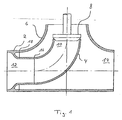
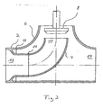
- FIGS. 1 and 2 Referenced Shown is a valve with an input 12 and an output 14, which can be connected to pipelines.
- the inlet 12 and the outlet 14 of the valve are interconnected by a flow channel which can be opened and closed by means of a poppet 8, the valve control for shifting the valve plug 8 between the open and the closed position is not shown.
- the valve itself consists of a reducer 2 cylindrical basic shape, to which at a junction 16, a manifold 4 is added.
- the manifold end 10 at the other end of the manifold 4 can be opened or closed with the poppet 8.
- the reducer 2 further forms the input 12.
- a T-piece 6 is attached to the reducer 2 at a junction 18 such that the attached to the reducer 2 manifold 4 is disposed in the interior of the T-piece 6.
- the reducer 2, the manifold 4 and the tee 6 are made of a high-purity steel having no segregation zones and, for example, electroslag remelted (ESR), the material subsequently being forged or pressed.
- ESR electroslag remelted
- the reducer 2 is made by means of turning, milling, forging, pressing or precision casting from a blank 20, which may be a forging blank or a cut-to-length section of a pipe.
- the blank 20 has a cylindrical basic shape with a central passage, so that the blank 20 before its further processing can be easily checked for accuracy (discontinuities).
- the review of the blank for accuracy (discontinuities) means Method for non-destructive material testing, preferably carried out by an ultrasonic volume test using a vertical test head.
- a next step is made from the blank 20, the reducer 2 by means of turning, milling, forging, pressing or investment casting.
- the reducer 2 has in its final form a first and second connecting portion 24, 26 of large diameter, which face each other, and a connecting portion 22 with a small diameter.
- the first large diameter port portion 24 later forms the inlet 12 of the valve and may be connected to a conduit while the second large diameter port portion 26 serves to connect to a T-piece 6.
- the small-diameter terminal portion 22 serves to connect the T-piece 2 to a manifold 4. At this time, the small-diameter terminal portion 22 is elongated with respect to the second large-diameter terminal portion 26.
- the joint 16 between the small diameter portion of the reducer 2 can be connected to the manifold 4 by welding.
- This weld in the region of the connection point 16 is easily accessible and can be tested by a method for non-destructive material testing, preferably by an ultrasonic volume test using a vertical test head.
- the manifold 4 connected to the reducer 2 is inserted into the interior of the T-piece 6 so as to be located inside the T-piece 6. Subsequently, at the junction 18 between the reducer 2 and the Manifold 4 with the tee 6 by welding a connection between the second large diameters of the reducer 2 and the tee 6 made.
- connection point 18 between the reducer 2, the manifold 4 and the tee 6 by means of non-destructive materials testing, preferably by an ultrasonic volume test using a vertical probe, since the junction 18 to the reducer 2 with the manifold 4 and the T-piece 6 is easily accessible.
- the valve is provided with a sheath 28, so that the valve is formed jacketed jacketed and the space between the valve and the double-walled casing 28 can be monitored for leaks or room for a vacuum insulation is given.
- the sheath 28 consists of two halves, which are attached to the valve and welded along seams.
- the sheath 28 on a plurality of supports 30, which serve the attachment and / or adjustment to the outer jacket of the valve.
- the seams between parts of the sheath 28 may be inspected by a nondestructive material testing method, preferably by ultrasonic volume testing using a vertical test head, so as to ensure that even the welds of the sheath 28 are free of defects.
- the supports 30 are arranged with respect to the welds such that the welds spring back and are not arranged in the region of the supports 30.
- valve plug 8 is mounted together with the valve control, so that a double-walled valve is available for the highest safety requirements.
Landscapes
- Engineering & Computer Science (AREA)
- General Engineering & Computer Science (AREA)
- Mechanical Engineering (AREA)
- Pressure Welding/Diffusion-Bonding (AREA)
- Investigating Or Analyzing Materials By The Use Of Ultrasonic Waves (AREA)
- Investigating Strength Of Materials By Application Of Mechanical Stress (AREA)
- Inks, Pencil-Leads, Or Crayons (AREA)
- Printing Methods (AREA)
- Filtering Of Dispersed Particles In Gases (AREA)
Claims (13)
- Procédé de fabrication d'un composant soumis à pression pour boîtier de robinet, de pompe, d'échangeur de chaleur, de répartiteur, ou de filtre, constitué d'une pièce de réduction (2), un coude (4)et une pièce en T formant un boîtier (6) comportant successivement les étapes suivantes :- préparation d'un coude (4), d'une pièce en T formant un boîtier ainsi qu'une ébauche (20) de la pièce de réduction (2),- contrôle de l'ébauche sur la présence de défauts par un procédé d'essais de matériau sans destruction de matériau,- usinage par déformation ou enlèvement de matière de l'ébauche avec façonnage de la pièce de réduction (2) avec au moins une section de raccordement (24, 26) de grand diamètre ainsi que section de raccordement (22) de petit diamètre,- raccordement de la section de raccordement (22) de petit diamètre de la pièce de réduction (2) avec le coude (4) et ensuite- raccordement de la section de raccordement de grand diamètre avec la pièce en T.
- Procédé selon la revendication 1, caractérisé en ce que l'ébauche (20) est une section d'un tube ou une ébauche de forge.
- Procédé selon la revendication 1 ou 2, caractérisé en ce que la pièce de réduction (2) est fabriquée à partir de l'ébauche (20) par tournage, fraisage, forgeage, pressage ou moulage de précision.
- Procédé selon la revendication 1, caractérisé en ce qu'une liaison par soudure est produite au point de liaison (16) entre la pièce de réduction (2) et le coude (4).
- Procédé selon la revendication 1 ou 4, caractérisé en ce que le point de liaison (16) est contrôlé au moyen d'un procédé d'essais de matériau sans destruction de matériau.
- Procédé selon la revendication 1, caractérisé en ce qu'une liaison par soudure est produite au point de liaison (18) entre la pièce de réduction (2) et la pièce en T.
- Procédé selon la revendication 6, caractérisé en ce que le point de liaison (18) est contrôlé par un procédé d'essais de matériau sans destruction de matériau.
- Procédé selon l'une des revendications précédentes, caractérisé en ce que la pièce de réduction (2), le coude (4) ou la pièce en T (6) sont fabriqués en un matériau de refusion de laitier électrique.
- Procédé selon l'une des revendications précédentes, caractérisé en ce que le matériau de la pièce de réduction (2), du coude (4) ou de la pièce en T (6) est forgé ou pressé.
- Procédé selon l'une des revendications précédentes, caractérisé en ce que le composant soumis à pression est pourvu d'une enveloppe (28).
- Procédé selon la revendication 10, caractérisé en ce que les cordons de liaison de l'enveloppe (28) sont testés au moyen de procédés d'essais de matériau sans destruction de matériau.
- Procédé selon l'une des revendications précédentes, caractérisé en ce qu'un test de volume aux ultrasons est effectué.
- Procédé selon la revendication 12, caractérisé en ce qu'on utilise pour le test de volume aux ultrasons une tête de test verticale.
Applications Claiming Priority (2)
| Application Number | Priority Date | Filing Date | Title |
|---|---|---|---|
| DE102004057682A DE102004057682B4 (de) | 2004-11-29 | 2004-11-29 | Verfahren zur Herstellung eines drucktragenden Bauteils |
| PCT/EP2005/005449 WO2006058564A1 (fr) | 2004-11-29 | 2005-05-19 | Procede de fabrication d'un composant supportant une pression |
Publications (2)
| Publication Number | Publication Date |
|---|---|
| EP1819953A1 EP1819953A1 (fr) | 2007-08-22 |
| EP1819953B1 true EP1819953B1 (fr) | 2009-10-28 |
Family
ID=34969155
Family Applications (1)
| Application Number | Title | Priority Date | Filing Date |
|---|---|---|---|
| EP05742948A Expired - Lifetime EP1819953B1 (fr) | 2004-11-29 | 2005-05-19 | Procede de fabrication d'un composant supportant une pression |
Country Status (6)
| Country | Link |
|---|---|
| US (1) | US20080000081A1 (fr) |
| EP (1) | EP1819953B1 (fr) |
| AT (1) | ATE447129T1 (fr) |
| DE (2) | DE102004057682B4 (fr) |
| RU (1) | RU2007124432A (fr) |
| WO (1) | WO2006058564A1 (fr) |
Families Citing this family (7)
| Publication number | Priority date | Publication date | Assignee | Title |
|---|---|---|---|---|
| ES2270744B2 (es) * | 2006-12-15 | 2007-10-01 | Gala-Sol, S.A. | Regulador de presion. |
| DE102011109071A1 (de) * | 2011-07-30 | 2013-01-31 | Sms Meer Gmbh | Rohrschmiedeverfahren mit urgeformten Hohlblock |
| RU2486022C1 (ru) * | 2011-12-08 | 2013-06-27 | Открытое Акционерное Общество "Дефорт" | Способ изготовления тройников высокого давления |
| CN103692149B (zh) * | 2012-09-27 | 2015-12-02 | 江苏威鹰机械有限公司 | 过滤器壳体精锻塑性成型生产工艺 |
| CN103978343B (zh) * | 2014-04-17 | 2016-08-24 | 中信重工机械股份有限公司 | 一种大型磨机用给料弯管的加工方法 |
| CN104759845A (zh) * | 2015-03-20 | 2015-07-08 | 高灵军 | 一种轴承加工工艺 |
| CN105855806B (zh) * | 2016-05-16 | 2018-01-16 | 苏州博豪精密机械有限公司 | 一种弯套筒的加工工艺 |
Family Cites Families (9)
| Publication number | Priority date | Publication date | Assignee | Title |
|---|---|---|---|---|
| DE533075C (de) * | 1929-12-19 | 1931-09-12 | Schaeffer & Budenberg G M B H | Gehaeuse fuer Durchgangsabsperrventile |
| FR1104746A (fr) * | 1954-07-20 | 1955-11-23 | Bergische Stahlindustrie | Procédé de fabrication de boîtes de soupapes |
| US3511272A (en) * | 1967-12-11 | 1970-05-12 | M & J Valve Co | Flow-t construction |
| BE795688A (fr) * | 1972-03-01 | 1973-06-18 | Mitsubishi Heavy Ind Ltd | Perfectionnements apportes et/ou relatifs a la fabrication d'articles metalliques |
| GB1459484A (en) * | 1974-02-11 | 1976-12-22 | Sun Forge Operations Ltd | Sphere passing tees for piping systems |
| JPH0649888B2 (ja) * | 1989-03-24 | 1994-06-29 | 新日本製鐵株式会社 | 表面被覆金属の製造方法 |
| DD291401A5 (de) * | 1990-01-02 | 1991-06-27 | Federnwerk,De | Verfahren und vorrichtung zum pruefen von metallbaendern |
| WO1992018862A1 (fr) * | 1991-04-19 | 1992-10-29 | Kawasaki Jukogyo Kabushiki Kaisha | Procede et dispositif pour la detection de defauts au moyen d'ondes ultrasonores |
| DE20209981U1 (de) * | 2002-06-27 | 2002-11-21 | Daume Regelarmaturen GmbH, 30916 Isernhagen | Ventilanordnung zur Verwendung in Rohrleitungssystemen für strömungsfähige Medien |
-
2004
- 2004-11-29 DE DE102004057682A patent/DE102004057682B4/de not_active Expired - Fee Related
-
2005
- 2005-05-19 DE DE502005008423T patent/DE502005008423D1/de not_active Expired - Lifetime
- 2005-05-19 RU RU2007124432/06A patent/RU2007124432A/ru not_active Application Discontinuation
- 2005-05-19 AT AT05742948T patent/ATE447129T1/de not_active IP Right Cessation
- 2005-05-19 EP EP05742948A patent/EP1819953B1/fr not_active Expired - Lifetime
- 2005-05-19 WO PCT/EP2005/005449 patent/WO2006058564A1/fr not_active Ceased
-
2007
- 2007-05-29 US US11/806,072 patent/US20080000081A1/en not_active Abandoned
Also Published As
| Publication number | Publication date |
|---|---|
| US20080000081A1 (en) | 2008-01-03 |
| DE102004057682B4 (de) | 2007-11-15 |
| ATE447129T1 (de) | 2009-11-15 |
| EP1819953A1 (fr) | 2007-08-22 |
| RU2007124432A (ru) | 2009-01-10 |
| DE102004057682A1 (de) | 2006-06-01 |
| WO2006058564A1 (fr) | 2006-06-08 |
| DE502005008423D1 (de) | 2009-12-10 |
Similar Documents
| Publication | Publication Date | Title |
|---|---|---|
| EP3391007B1 (fr) | Capteur pour tuyau à haute pression et son procédé de fabrication | |
| EP1819953B1 (fr) | Procede de fabrication d'un composant supportant une pression | |
| EP3452236A1 (fr) | Procédé de fabrication d'un élément de raccordement tubulaire cintré | |
| DE29502825U1 (de) | Piezoresistiver Drucksensor oder Druckaufnehmer | |
| EP2696062A1 (fr) | Caloporteur | |
| DE102018107017A1 (de) | Muffe mit Sensoranschluss und Verfahren zum Anbringen eines Sensors an einer Rohrleitung | |
| DE202022104099U1 (de) | Ventilblock für eine Armatur und Armatur mit einem solchen Ventilblock | |
| EP1675696B1 (fr) | Procede permettant d'ajuster des caracteristiques et proprietes de qualite specifiques pour des tuyaux a l'aide d'essais de pression | |
| DE202004019057U1 (de) | Drucktragendes Bauteil | |
| EP4034791B1 (fr) | Procédé de fabrication d'un agencement de canalisation et agencement de canalisation | |
| EP3587110A2 (fr) | Ensemble de tuyauterie métallique pourvu de pièce de raccordement fabriquée de manière générative | |
| WO2007059930A1 (fr) | Garniture pour tuyau a tube ondule et procede de raccordement | |
| EP4155598B1 (fr) | Armature de pression pour flux de matériaux, procédé de fonctionnement d'armatures de pression et utilisation | |
| DE10028737A1 (de) | Doppel-oder mehrwandiges Bauteil zur Verwendung in Rohrleitungssystemen | |
| DE19954812C2 (de) | Vorrichtung zum Schutz von Schweißnähten im Wurzelbereich unter Verwendung von Schutzgas | |
| DE102011075624A1 (de) | Reinigungsanlage für Werkstücke mit Fluidkanal | |
| DE3836326A1 (de) | Verbindungsstueck zum verbinden wenigstens zweier in verschiedene richtungen verlaufender, insbesondere aus thermoplastischem kunststoff bestehender rohrleitungen sowie ein verfahren zur herstellung des verbindungsstuecks | |
| DE8690024U1 (de) | Übergangsstück | |
| EP1712820B1 (fr) | Boîtier de robinet à boisseau sphérique | |
| DE102017100378A1 (de) | Verfahren zur Herstellung einer Verbindung zweier Edelstahlrohre, Rohradapter zur Anwendung des Verfahrens und Verbindungsanordnung der Edelstahlrohre | |
| WO1995020738A1 (fr) | Corps d'appareil de robinetterie | |
| DE19713370A1 (de) | Armaturengehäuse | |
| AT509445B1 (de) | Nasselektrofilter | |
| DE2427783B2 (de) | Geschweisstes gehaeuse fuer einen kugelhahn | |
| DE19948142A1 (de) | Verfahren zur Herstellung eines Preßfittings |
Legal Events
| Date | Code | Title | Description |
|---|---|---|---|
| PUAI | Public reference made under article 153(3) epc to a published international application that has entered the european phase |
Free format text: ORIGINAL CODE: 0009012 |
|
| 17P | Request for examination filed |
Effective date: 20070629 |
|
| AK | Designated contracting states |
Kind code of ref document: A1 Designated state(s): AT BE BG CH CY CZ DE DK EE ES FI FR GB GR HU IE IS IT LI LT LU MC NL PL PT RO SE SI SK TR |
|
| DAX | Request for extension of the european patent (deleted) | ||
| 17Q | First examination report despatched |
Effective date: 20080418 |
|
| GRAP | Despatch of communication of intention to grant a patent |
Free format text: ORIGINAL CODE: EPIDOSNIGR1 |
|
| GRAS | Grant fee paid |
Free format text: ORIGINAL CODE: EPIDOSNIGR3 |
|
| GRAA | (expected) grant |
Free format text: ORIGINAL CODE: 0009210 |
|
| AK | Designated contracting states |
Kind code of ref document: B1 Designated state(s): AT BE BG CH CY CZ DE DK EE ES FI FR GB GR HU IE IS IT LI LT LU MC NL PL PT RO SE SI SK TR |
|
| REG | Reference to a national code |
Ref country code: GB Ref legal event code: FG4D Free format text: NOT ENGLISH |
|
| REG | Reference to a national code |
Ref country code: CH Ref legal event code: EP |
|
| REG | Reference to a national code |
Ref country code: IE Ref legal event code: FG4D |
|
| REF | Corresponds to: |
Ref document number: 502005008423 Country of ref document: DE Date of ref document: 20091210 Kind code of ref document: P |
|
| LTIE | Lt: invalidation of european patent or patent extension |
Effective date: 20091028 |
|
| NLV1 | Nl: lapsed or annulled due to failure to fulfill the requirements of art. 29p and 29m of the patents act | ||
| PG25 | Lapsed in a contracting state [announced via postgrant information from national office to epo] |
Ref country code: PT Free format text: LAPSE BECAUSE OF FAILURE TO SUBMIT A TRANSLATION OF THE DESCRIPTION OR TO PAY THE FEE WITHIN THE PRESCRIBED TIME-LIMIT Effective date: 20100301 Ref country code: LT Free format text: LAPSE BECAUSE OF FAILURE TO SUBMIT A TRANSLATION OF THE DESCRIPTION OR TO PAY THE FEE WITHIN THE PRESCRIBED TIME-LIMIT Effective date: 20091028 Ref country code: ES Free format text: LAPSE BECAUSE OF FAILURE TO SUBMIT A TRANSLATION OF THE DESCRIPTION OR TO PAY THE FEE WITHIN THE PRESCRIBED TIME-LIMIT Effective date: 20100208 Ref country code: FI Free format text: LAPSE BECAUSE OF FAILURE TO SUBMIT A TRANSLATION OF THE DESCRIPTION OR TO PAY THE FEE WITHIN THE PRESCRIBED TIME-LIMIT Effective date: 20091028 Ref country code: SE Free format text: LAPSE BECAUSE OF FAILURE TO SUBMIT A TRANSLATION OF THE DESCRIPTION OR TO PAY THE FEE WITHIN THE PRESCRIBED TIME-LIMIT Effective date: 20091028 Ref country code: IS Free format text: LAPSE BECAUSE OF FAILURE TO SUBMIT A TRANSLATION OF THE DESCRIPTION OR TO PAY THE FEE WITHIN THE PRESCRIBED TIME-LIMIT Effective date: 20100228 |
|
| REG | Reference to a national code |
Ref country code: IE Ref legal event code: FD4D |
|
| PG25 | Lapsed in a contracting state [announced via postgrant information from national office to epo] |
Ref country code: SI Free format text: LAPSE BECAUSE OF FAILURE TO SUBMIT A TRANSLATION OF THE DESCRIPTION OR TO PAY THE FEE WITHIN THE PRESCRIBED TIME-LIMIT Effective date: 20091028 Ref country code: PL Free format text: LAPSE BECAUSE OF FAILURE TO SUBMIT A TRANSLATION OF THE DESCRIPTION OR TO PAY THE FEE WITHIN THE PRESCRIBED TIME-LIMIT Effective date: 20091028 Ref country code: CY Free format text: LAPSE BECAUSE OF FAILURE TO SUBMIT A TRANSLATION OF THE DESCRIPTION OR TO PAY THE FEE WITHIN THE PRESCRIBED TIME-LIMIT Effective date: 20091028 |
|
| PG25 | Lapsed in a contracting state [announced via postgrant information from national office to epo] |
Ref country code: IE Free format text: LAPSE BECAUSE OF FAILURE TO SUBMIT A TRANSLATION OF THE DESCRIPTION OR TO PAY THE FEE WITHIN THE PRESCRIBED TIME-LIMIT Effective date: 20091028 Ref country code: RO Free format text: LAPSE BECAUSE OF FAILURE TO SUBMIT A TRANSLATION OF THE DESCRIPTION OR TO PAY THE FEE WITHIN THE PRESCRIBED TIME-LIMIT Effective date: 20091028 Ref country code: BG Free format text: LAPSE BECAUSE OF FAILURE TO SUBMIT A TRANSLATION OF THE DESCRIPTION OR TO PAY THE FEE WITHIN THE PRESCRIBED TIME-LIMIT Effective date: 20100128 Ref country code: EE Free format text: LAPSE BECAUSE OF FAILURE TO SUBMIT A TRANSLATION OF THE DESCRIPTION OR TO PAY THE FEE WITHIN THE PRESCRIBED TIME-LIMIT Effective date: 20091028 Ref country code: DK Free format text: LAPSE BECAUSE OF FAILURE TO SUBMIT A TRANSLATION OF THE DESCRIPTION OR TO PAY THE FEE WITHIN THE PRESCRIBED TIME-LIMIT Effective date: 20091028 |
|
| PG25 | Lapsed in a contracting state [announced via postgrant information from national office to epo] |
Ref country code: CZ Free format text: LAPSE BECAUSE OF FAILURE TO SUBMIT A TRANSLATION OF THE DESCRIPTION OR TO PAY THE FEE WITHIN THE PRESCRIBED TIME-LIMIT Effective date: 20091028 Ref country code: SK Free format text: LAPSE BECAUSE OF FAILURE TO SUBMIT A TRANSLATION OF THE DESCRIPTION OR TO PAY THE FEE WITHIN THE PRESCRIBED TIME-LIMIT Effective date: 20091028 |
|
| PLBE | No opposition filed within time limit |
Free format text: ORIGINAL CODE: 0009261 |
|
| STAA | Information on the status of an ep patent application or granted ep patent |
Free format text: STATUS: NO OPPOSITION FILED WITHIN TIME LIMIT |
|
| 26N | No opposition filed |
Effective date: 20100729 |
|
| PG25 | Lapsed in a contracting state [announced via postgrant information from national office to epo] |
Ref country code: GR Free format text: LAPSE BECAUSE OF FAILURE TO SUBMIT A TRANSLATION OF THE DESCRIPTION OR TO PAY THE FEE WITHIN THE PRESCRIBED TIME-LIMIT Effective date: 20100129 |
|
| BERE | Be: lapsed |
Owner name: DAUME REGELARMATUREN G.M.B.H. Effective date: 20100531 |
|
| PG25 | Lapsed in a contracting state [announced via postgrant information from national office to epo] |
Ref country code: MC Free format text: LAPSE BECAUSE OF NON-PAYMENT OF DUE FEES Effective date: 20100531 |
|
| REG | Reference to a national code |
Ref country code: CH Ref legal event code: PL |
|
| GBPC | Gb: european patent ceased through non-payment of renewal fee |
Effective date: 20100519 |
|
| REG | Reference to a national code |
Ref country code: FR Ref legal event code: ST Effective date: 20110131 |
|
| PG25 | Lapsed in a contracting state [announced via postgrant information from national office to epo] |
Ref country code: LI Free format text: LAPSE BECAUSE OF NON-PAYMENT OF DUE FEES Effective date: 20100531 Ref country code: CH Free format text: LAPSE BECAUSE OF NON-PAYMENT OF DUE FEES Effective date: 20100531 |
|
| PG25 | Lapsed in a contracting state [announced via postgrant information from national office to epo] |
Ref country code: BE Free format text: LAPSE BECAUSE OF NON-PAYMENT OF DUE FEES Effective date: 20100531 Ref country code: IT Free format text: LAPSE BECAUSE OF FAILURE TO SUBMIT A TRANSLATION OF THE DESCRIPTION OR TO PAY THE FEE WITHIN THE PRESCRIBED TIME-LIMIT Effective date: 20091028 |
|
| PG25 | Lapsed in a contracting state [announced via postgrant information from national office to epo] |
Ref country code: FR Free format text: LAPSE BECAUSE OF NON-PAYMENT OF DUE FEES Effective date: 20100531 |
|
| PG25 | Lapsed in a contracting state [announced via postgrant information from national office to epo] |
Ref country code: GB Free format text: LAPSE BECAUSE OF NON-PAYMENT OF DUE FEES Effective date: 20100519 |
|
| PG25 | Lapsed in a contracting state [announced via postgrant information from national office to epo] |
Ref country code: AT Free format text: LAPSE BECAUSE OF NON-PAYMENT OF DUE FEES Effective date: 20100519 |
|
| REG | Reference to a national code |
Ref country code: DE Ref legal event code: R082 Ref document number: 502005008423 Country of ref document: DE Representative=s name: WAGNER DR. HERRGUTH, DE |
|
| REG | Reference to a national code |
Ref country code: DE Ref legal event code: R082 Ref document number: 502005008423 Country of ref document: DE Representative=s name: PATENTANWAELTE WAGNER DR. HERRGUTH, DE Effective date: 20111205 Ref country code: DE Ref legal event code: R081 Ref document number: 502005008423 Country of ref document: DE Owner name: DAUME REGELARMATUREN GMBH, DE Free format text: FORMER OWNER: DAUME REGELARMATUREN GMBH, 30916 ISERNHAGEN, DE Effective date: 20111205 Ref country code: DE Ref legal event code: R082 Ref document number: 502005008423 Country of ref document: DE Representative=s name: WAGNER DR. HERRGUTH, DE Effective date: 20111205 Ref country code: DE Ref legal event code: R082 Ref document number: 502005008423 Country of ref document: DE Representative=s name: WAGNER, DR. HERRGUTH & PARTNER PATENTANWAELTE , DE Effective date: 20111205 Ref country code: DE Ref legal event code: R082 Ref document number: 502005008423 Country of ref document: DE Representative=s name: WAGNER, DR. HERRGUTH PATENTANWAELTE, DE Effective date: 20111205 |
|
| PG25 | Lapsed in a contracting state [announced via postgrant information from national office to epo] |
Ref country code: HU Free format text: LAPSE BECAUSE OF FAILURE TO SUBMIT A TRANSLATION OF THE DESCRIPTION OR TO PAY THE FEE WITHIN THE PRESCRIBED TIME-LIMIT Effective date: 20100429 Ref country code: LU Free format text: LAPSE BECAUSE OF NON-PAYMENT OF DUE FEES Effective date: 20100519 Ref country code: NL Free format text: LAPSE BECAUSE OF FAILURE TO SUBMIT A TRANSLATION OF THE DESCRIPTION OR TO PAY THE FEE WITHIN THE PRESCRIBED TIME-LIMIT Effective date: 20091028 |
|
| PG25 | Lapsed in a contracting state [announced via postgrant information from national office to epo] |
Ref country code: TR Free format text: LAPSE BECAUSE OF FAILURE TO SUBMIT A TRANSLATION OF THE DESCRIPTION OR TO PAY THE FEE WITHIN THE PRESCRIBED TIME-LIMIT Effective date: 20091028 |
|
| REG | Reference to a national code |
Ref country code: DE Ref legal event code: R082 Ref document number: 502005008423 Country of ref document: DE Representative=s name: WAGNER DR. HERRGUTH, DE |
|
| REG | Reference to a national code |
Ref country code: DE Ref legal event code: R082 Ref document number: 502005008423 Country of ref document: DE Representative=s name: PATENTANWAELTE WAGNER DR. HERRGUTH, DE Effective date: 20130122 Ref country code: DE Ref legal event code: R081 Ref document number: 502005008423 Country of ref document: DE Owner name: DAUME REGELARMATUREN GMBH, DE Free format text: FORMER OWNER: DAUME, BRITTA, 30938 BURGWEDEL, DE Effective date: 20130122 Ref country code: DE Ref legal event code: R082 Ref document number: 502005008423 Country of ref document: DE Representative=s name: WAGNER, DR. HERRGUTH & PARTNER PATENTANWAELTE , DE Effective date: 20130122 Ref country code: DE Ref legal event code: R082 Ref document number: 502005008423 Country of ref document: DE Representative=s name: WAGNER, DR. HERRGUTH PATENTANWAELTE, DE Effective date: 20130122 |
|
| PGFP | Annual fee paid to national office [announced via postgrant information from national office to epo] |
Ref country code: DE Payment date: 20150531 Year of fee payment: 11 |
|
| REG | Reference to a national code |
Ref country code: DE Ref legal event code: R119 Ref document number: 502005008423 Country of ref document: DE |
|
| PG25 | Lapsed in a contracting state [announced via postgrant information from national office to epo] |
Ref country code: DE Free format text: LAPSE BECAUSE OF NON-PAYMENT OF DUE FEES Effective date: 20161201 |