EP1820587A1 - Verfahren zur herstellung eines pulverkernpresskörpers und pulverkernpresskörper - Google Patents
Verfahren zur herstellung eines pulverkernpresskörpers und pulverkernpresskörper Download PDFInfo
- Publication number
- EP1820587A1 EP1820587A1 EP05783309A EP05783309A EP1820587A1 EP 1820587 A1 EP1820587 A1 EP 1820587A1 EP 05783309 A EP05783309 A EP 05783309A EP 05783309 A EP05783309 A EP 05783309A EP 1820587 A1 EP1820587 A1 EP 1820587A1
- Authority
- EP
- European Patent Office
- Prior art keywords
- compact
- soft magnetic
- magnetic powder
- pressure
- forming
- Prior art date
- Legal status (The legal status is an assumption and is not a legal conclusion. Google has not performed a legal analysis and makes no representation as to the accuracy of the status listed.)
- Granted
Links
Images



Classifications
-
- B—PERFORMING OPERATIONS; TRANSPORTING
- B22—CASTING; POWDER METALLURGY
- B22F—WORKING METALLIC POWDER; MANUFACTURE OF ARTICLES FROM METALLIC POWDER; MAKING METALLIC POWDER; APPARATUS OR DEVICES SPECIALLY ADAPTED FOR METALLIC POWDER
- B22F7/00—Manufacture of composite layers, workpieces, or articles, comprising metallic powder, by sintering the powder, with or without compacting wherein at least one part is obtained by sintering or compression
- B22F7/06—Manufacture of composite layers, workpieces, or articles, comprising metallic powder, by sintering the powder, with or without compacting wherein at least one part is obtained by sintering or compression of composite workpieces or articles from parts, e.g. to form tipped tools
-
- B—PERFORMING OPERATIONS; TRANSPORTING
- B22—CASTING; POWDER METALLURGY
- B22F—WORKING METALLIC POWDER; MANUFACTURE OF ARTICLES FROM METALLIC POWDER; MAKING METALLIC POWDER; APPARATUS OR DEVICES SPECIALLY ADAPTED FOR METALLIC POWDER
- B22F1/00—Metallic powder; Treatment of metallic powder, e.g. to facilitate working or to improve properties
- B22F1/16—Metallic particles coated with a non-metal
-
- B—PERFORMING OPERATIONS; TRANSPORTING
- B22—CASTING; POWDER METALLURGY
- B22F—WORKING METALLIC POWDER; MANUFACTURE OF ARTICLES FROM METALLIC POWDER; MAKING METALLIC POWDER; APPARATUS OR DEVICES SPECIALLY ADAPTED FOR METALLIC POWDER
- B22F3/00—Manufacture of workpieces or articles from metallic powder characterised by the manner of compacting or sintering; Apparatus specially adapted therefor ; Presses and furnaces
- B22F3/02—Compacting only
-
- H—ELECTRICITY
- H01—ELECTRIC ELEMENTS
- H01F—MAGNETS; INDUCTANCES; TRANSFORMERS; SELECTION OF MATERIALS FOR THEIR MAGNETIC PROPERTIES
- H01F1/00—Magnets or magnetic bodies characterised by the magnetic materials therefor; Selection of materials for their magnetic properties
- H01F1/01—Magnets or magnetic bodies characterised by the magnetic materials therefor; Selection of materials for their magnetic properties of inorganic materials
- H01F1/03—Magnets or magnetic bodies characterised by the magnetic materials therefor; Selection of materials for their magnetic properties of inorganic materials characterised by their coercivity
- H01F1/12—Magnets or magnetic bodies characterised by the magnetic materials therefor; Selection of materials for their magnetic properties of inorganic materials characterised by their coercivity of soft-magnetic materials
- H01F1/14—Magnets or magnetic bodies characterised by the magnetic materials therefor; Selection of materials for their magnetic properties of inorganic materials characterised by their coercivity of soft-magnetic materials metals or alloys
- H01F1/20—Magnets or magnetic bodies characterised by the magnetic materials therefor; Selection of materials for their magnetic properties of inorganic materials characterised by their coercivity of soft-magnetic materials metals or alloys in the form of particles, e.g. powder
- H01F1/22—Magnets or magnetic bodies characterised by the magnetic materials therefor; Selection of materials for their magnetic properties of inorganic materials characterised by their coercivity of soft-magnetic materials metals or alloys in the form of particles, e.g. powder pressed, sintered, or bound together
- H01F1/24—Magnets or magnetic bodies characterised by the magnetic materials therefor; Selection of materials for their magnetic properties of inorganic materials characterised by their coercivity of soft-magnetic materials metals or alloys in the form of particles, e.g. powder pressed, sintered, or bound together the particles being insulated
-
- H—ELECTRICITY
- H01—ELECTRIC ELEMENTS
- H01F—MAGNETS; INDUCTANCES; TRANSFORMERS; SELECTION OF MATERIALS FOR THEIR MAGNETIC PROPERTIES
- H01F41/00—Apparatus or processes specially adapted for manufacturing or assembling magnets, inductances or transformers; Apparatus or processes specially adapted for manufacturing materials characterised by their magnetic properties
- H01F41/02—Apparatus or processes specially adapted for manufacturing or assembling magnets, inductances or transformers; Apparatus or processes specially adapted for manufacturing materials characterised by their magnetic properties for manufacturing cores, coils, or magnets
- H01F41/0206—Manufacturing of magnetic cores by mechanical means
- H01F41/0246—Manufacturing of magnetic circuits by moulding or by pressing powder
-
- B—PERFORMING OPERATIONS; TRANSPORTING
- B22—CASTING; POWDER METALLURGY
- B22F—WORKING METALLIC POWDER; MANUFACTURE OF ARTICLES FROM METALLIC POWDER; MAKING METALLIC POWDER; APPARATUS OR DEVICES SPECIALLY ADAPTED FOR METALLIC POWDER
- B22F3/00—Manufacture of workpieces or articles from metallic powder characterised by the manner of compacting or sintering; Apparatus specially adapted therefor ; Presses and furnaces
- B22F3/24—After-treatment of workpieces or articles
- B22F2003/247—Removing material: carving, cleaning, grinding, hobbing, honing, lapping, polishing, milling, shaving, skiving, turning the surface
-
- B—PERFORMING OPERATIONS; TRANSPORTING
- B22—CASTING; POWDER METALLURGY
- B22F—WORKING METALLIC POWDER; MANUFACTURE OF ARTICLES FROM METALLIC POWDER; MAKING METALLIC POWDER; APPARATUS OR DEVICES SPECIALLY ADAPTED FOR METALLIC POWDER
- B22F3/00—Manufacture of workpieces or articles from metallic powder characterised by the manner of compacting or sintering; Apparatus specially adapted therefor ; Presses and furnaces
- B22F3/24—After-treatment of workpieces or articles
- B22F2003/248—Thermal after-treatment
-
- B—PERFORMING OPERATIONS; TRANSPORTING
- B22—CASTING; POWDER METALLURGY
- B22F—WORKING METALLIC POWDER; MANUFACTURE OF ARTICLES FROM METALLIC POWDER; MAKING METALLIC POWDER; APPARATUS OR DEVICES SPECIALLY ADAPTED FOR METALLIC POWDER
- B22F2998/00—Supplementary information concerning processes or compositions relating to powder metallurgy
- B22F2998/10—Processes characterised by the sequence of their steps
-
- Y—GENERAL TAGGING OF NEW TECHNOLOGICAL DEVELOPMENTS; GENERAL TAGGING OF CROSS-SECTIONAL TECHNOLOGIES SPANNING OVER SEVERAL SECTIONS OF THE IPC; TECHNICAL SUBJECTS COVERED BY FORMER USPC CROSS-REFERENCE ART COLLECTIONS [XRACs] AND DIGESTS
- Y10—TECHNICAL SUBJECTS COVERED BY FORMER USPC
- Y10T—TECHNICAL SUBJECTS COVERED BY FORMER US CLASSIFICATION
- Y10T428/00—Stock material or miscellaneous articles
- Y10T428/12—All metal or with adjacent metals
- Y10T428/12014—All metal or with adjacent metals having metal particles
Definitions
- the present invention generally relates to a method for producing a dust core compact, and the dust core compact. More particularly, the present invention relates to a method for producing a dust core compact fabricated using soft magnetic powder, and the dust core compact.
- Patent Document 1 Japanese Patent Laying-Open No. 2003-235186
- a plurality of magneto coil elements having recesses and projections formed at coupling portions are coupled to each other by engaging the recesses and projections with each other.
- the obtained magneto coil is placed within a housing, and thereafter the housing is cooled down. Since the housing shrinks as it cools down, the magneto coil is shrink-fitted on the inner peripheral surface of the housing.
- Patent Document 1 Japanese Patent Laying-Open No. 2003-235186
- the magneto coil element formed of a magnetic material such as a magnetic steel sheet may be formed with variations in dimensional accuracy, a gap or excess stress may be generated at the coupling portion between the magneto coil elements when the plurality of magneto coil elements are shrink-fitted on the inner peripheral surface of the housing.
- the generation of a gap or excess stress causes deterioration in magnetic properties of the magneto coil.
- one object of the present invention is to solve the aforementioned problems, and to provide a method for producing a dust core compact exhibiting a high strength and capable of being fabricated even when it has a complex shape, as well as to provide the dust core compact.
- a method for producing a dust core compact includes the steps of: forming a compact component by pressure-forming a first soft magnetic powder having an average particle diameter Da under a pressure Pa; and forming a compact by pressure-forming a second soft magnetic powder having an average particle diameter Db and the compact component under a pressure Pb.
- Average particle diameter Da of the first soft magnetic powder and average particle diameter Db of the second soft magnetic powder satisfy relationship Da/Db ⁇ 2.
- Pressures Pa and Pb applied during the pressure forming satisfy relationship Pa/Pb ⁇ 1/2.
- a compact component is formed by subjecting the first soft magnetic powder to pressure forming (hereinafter also referred to as preparatory molding), and thereafter the compact component and the second soft magnetic powder are subjected to pressure forming (hereinafter also referred to as final molding) to mold the second soft magnetic powder and to bond the compact component and the second soft magnetic powder to obtain a compact. Therefore, even when the compact has a complex shape, the compact can easily be formed in that shape with even density.
- the compact component is formed with a gap of a certain degree provided between particles of the first soft magnetic powder.
- particles of the second soft magnetic powder can be introduced into the gap by performing the final molding under relatively large pressure Pb satisfying the above relationship.
- the second soft magnetic powder has relatively small average particle diameter Db satisfying the relationship Da/Db ⁇ 2
- the particles of the second soft magnetic powder can easily be introduced into between the particles of the first soft magnetic powder. Consequently, the compact can be formed with the first and second soft magnetic powders intricately engaging with each other at a boundary position therebetween, thereby exhibiting excellent strength.
- the step of forming the compact component includes the step of forming the compact component by pressure-forming the first soft magnetic powder under pressure Pa of not more than 400 MPa.
- the preparatory molding can be performed with a larger gap provided between the particles of the first soft magnetic powder.
- the compact obtained by the final molding can exhibit a further improved strength.
- the step of forming the compact component includes the step of forming the compact component such that a surface thereof to be bonded to the second soft magnetic powder is shaped to have recesses and projections.
- a contact area between the compact component and the second soft magnetic powder can be increased in the final molding.
- the first and second soft magnetic powders can engage with each other more intricately, further improving the strength of the compact.
- the first and second soft magnetic powders each include a plurality of metal magnetic particles and an insulating coating film surrounding a surface of each of the plurality of metal magnetic particles.
- surfaces of the first and second soft magnetic powders are covered with the insulating coating film, and thus metal bonding between the particles cannot be attained when the pressure forming is performed. Consequently, the present invention, which improves the strength of the compact by the effect of physical engagement between the first magnetic powder and the second soft magnetic powder, can be utilized more effectively.
- the method for producing a dust core compact further includes the step of heat-treating the compact at a temperature of not less than 200°C and not more than 500°C after the step of forming the compact.
- the heat treatment of the compact at a temperature of not less than 200°C can eliminate an interface between the insulating coating films bonded to each other by the pressure forming, and thus the compact can exhibit a further improved strength.
- insulation breakdown of the insulating coating film by heat can be suppressed.
- the insulating coating film can sufficiently serve as an insulating layer between the metal magnetic particles.
- a dust core compact according to the present invention is a dust core compact fabricated using any of the methods for producing a dust core compact described above.
- the particles constituting the second soft magnetic powder engage the particles constituting the first soft magnetic powder at a boundary position between the first soft magnetic powder and the second soft magnetic powder.
- the dust core compact configured as described above, has a structure in which the particles of the first and second soft magnetic powders engage with each other at the boundary position therebetween, and thus excellent bond strength can be achieved at that position.
- a method for producing a dust core compact exhibiting a high strength and capable of being fabricated even when it has a complex shape, and the dust core compact can be provided.
- Figs. 1 to 6 are schematic views showing steps of a method for producing a dust core compact in a first embodiment of the present invention.
- the state of a soft magnetic powder in each step is shown schematically.
- steps of fabricating a dust core using the method for producing a dust core compact in the present embodiment will be described.
- the soft magnetic particle includes a metal magnetic particle and an insulating coating film surrounding the surface of the metal magnetic particle.
- Soft magnetic powder 21 has an average particle diameter Da.
- Soft magnetic powder 21 having such an average particle diameter can be obtained for example by classification using a sieve having an appropriate mesh size. It is to be noted that the average particle diameter described herein refers to a particle diameter obtained when the sum of masses of particles added in ascending order of particle diameter in a histogram of particle diameters measured by laser scattering and diffraction reaches 50% of the total mass, that is, a 50% particle diameter D.
- the metal magnetic particle is made of, for example, iron (Fe), an iron (Fe)-silicon (Si) based alloy, an iron (Fe)-nitrogen (N) based alloy, an iron (Fe)-nickel (Ni) based alloy, an iron (Fe)-carbon (C) based alloy, an iron (Fe)-boron (B) based alloy, an iron (Fe)-cobalt (Co) based alloy, an iron (Fe)-phosphorus (P) based alloy, an iron (Fe)-nickel (Ni)-cobalt (Co) based alloy, and an iron (Fe)-aluminum (Al)-silicon (Si) based alloy.
- the metal magnetic particle may be made of a single metal, or may be an alloy.
- the insulating coating film is formed by treating the metal magnetic particle with phosphoric acid. Further, the insulating coating film preferably contains an oxide. As the insulating coating film containing an oxide, an oxide insulator can be used, such as iron phosphate containing phosphorus and iron, manganese phosphate, zinc phosphate, calcium phosphate, silicon oxide, titanium oxide, aluminum oxide, or zirconia oxide. The insulating coating film may cover the metal magnetic particle in one layer, or in multiple layers.
- the insulating coating film serves as an insulating layer between the metal magnetic particles.
- the dust core to be obtained can have an increased electric resistivity p. This can suppress eddy current from flowing between the metal magnetic particles, and reduce core loss of the dust core due to occurrence of the eddy current.
- prepared soft magnetic powder 21 is filled into a die 10 of a molding apparatus and pressure-formed under a pressure Pa (a preparatory molding step).
- pressure Pa is preferably not more than 400 MPa.
- the pressure forming is preferably performed in an inert gas atmosphere or a reduced-pressure atmosphere, which can suppress soft magnetic powder 21 from being oxidized by oxygen in the atmosphere.
- a compact component 22 is fabricated by the preparatory molding step described above. The shape of compact component 22 is changed as appropriate depending on the shape of a compact to be obtained finally in a subsequent step.
- a newly prepared soft magnetic powder 31 is then placed in die 10 of the molding apparatus, together with compact component 22 fabricated by the previous preparatory molding step.
- Soft magnetic powder 31 is similar in construction to soft magnetic powder 21 used in the preparatory molding step, and has an average particle diameter Db.
- Soft magnetic powder 31 having average particle diameter Db can be obtained by classification performed in the same way as in soft magnetic powder 21.
- the average particle diameter described herein also refers to 50% particle diameter D described above.
- Average particle diameter Da of soft magnetic powder 21 and average particle diameter Db of soft magnetic powder 31 satisfy relationship Da/Db ⁇ 2.
- compact component 22 and soft magnetic powder 31 placed in die 10 are then pressure-formed under a pressure Pb (a final molding step).
- Pressure Pa applied during the preparatory molding and pressure Pb applied during the final molding satisfy relationship Pa/Pb ⁇ 1/2.
- the pressure forming is preferably performed in an inert gas atmosphere or a reduced-pressure atmosphere.
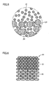
- Fig. 5 schematically shows the state of the soft magnetic powders in the step shown in Fig. 4, in a representation different from Fig. 4.
- compact component 22 is molded with a gap 23 provided between the particles of soft magnetic powder 21, because pressure Pa applied during the preparatory molding is controlled, relative to pressure Pb applied during the final molding, to have a value satisfying the relationship Pa/Pb ⁇ 1/2.
- particles of soft magnetic powder 31 are introduced into gap 23 one after another when soft magnetic powder 31 is applied with pressure Pb during the final molding.
- average particle diameter Da of soft magnetic powder 21 and average particle diameter Db of soft magnetic powder 31 satisfy the relationship Da/Db ⁇ 2, soft magnetic powder 31 having relatively small average particle diameter Db can easily be introduced into gap 23 formed between the particles of soft magnetic powder 21 having relatively large average particle diameter Da.
- a compact 41 is fabricated by the final molding step described above. Thereafter, obtained compact 41 may be heat-treated at a temperature of not less than 200°C and not more than 500°C.
- the heat treatment can soften the insulating coating film constituting compact 41 and eliminate an interface extending between adjacent insulating coating films. Thereby, the strength of compact 41 can be improved. Further, the heat treatment can reduce distortion generated inside compact 41 due to the pressure forming, and reduce hysteresis loss of the dust core to be obtained in a subsequent step.
- the temperature for the heat treatment at not more than 500°C, the insulating coating film can be prevented from being deteriorated by heat. Thereby, the state where the metal magnetic particle is covered with the insulating layer can be maintained, and eddy current loss of the dust core to be obtained in a subsequent step can be reduced.
- compact 41 is appropriately worked by such as extrusion, cutting, or the like, to be completed as the dust core.
- the method for producing a dust core compact in the first embodiment of the present invention includes the steps of: forming compact component 22 by pressure-forming soft magnetic powder 21 as the first soft magnetic powder having average particle diameter Da under pressure Pa; and forming compact 41 by pressure-forming soft magnetic powder 31 as the second soft magnetic powder having average particle diameter Db and compact component 22 under pressure Pb.
- Average particle diameter Da of soft magnetic powder 21 and average particle diameter Db of soft magnetic powder 31 satisfy the relationship Da/Db ⁇ 2.
- Pressures Pa and Pb applied during the pressure forming satisfy the relationship Pa/Pb ⁇ 1/2.
- compact 41 having a final shape is fabricated by two molding steps, that is, the preparatory molding step and the final molding step. Therefore, even when compact 41 has a complex shape, that shape can easily be attained. Further, since compact 41 is fabricated by pressure-forming compact component 22 and soft magnetic powder 31 during the final molding, there is no need to use an adhesive or the like. Accordingly, compact 41 has no nonmagnetic layer such as an adhesive therein, and thus a dust core having excellent magnetic properties can be obtained.
- the junction location between compact component 22 and soft magnetic powder 31 can obtain the state where the particles of soft magnetic powders 21 and 31 intricately engage with each other. Thereby, both powders are firmly bonded, and excellent bond strength can be achieved.
- the method for producing a dust core compact in the present embodiment can be used to fabricate a dust core, a choke coil, a switching power supply element, a magnetic head, various types of motor components, a solenoid for automobile, various types of magnetic sensors and electromagnetic valves, and the like. Further, without being limited to these magnetic components, the method can also be used to subject such as iron powder having no insulating coating film to pressure forming to fabricate a mechanical component.
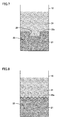
- Fig. 7 shows the step described in the first embodiment with reference to Fig. 3.
- a method for producing a dust core compact in the present embodiment has steps basically the same as those of the method for producing a dust core compact in the first embodiment. Hereinafter, description of the same step will not be repeated.
- a recess 25 is formed in a top surface 22a of compact component 22 in the preparatory molding step.
- soft magnetic powder 31 is filled on top surface 22a having recess 25 formed therein, and the final molding step is performed under a predetermined pressure.
- compact 41 can be fabricated with soft magnetic powders 21 and 31 further engaging with each other. Thereby, the strength of compact 41 can further be improved.
- Fig. 8 shows a variation of the method for producing a dust core compact in the second embodiment of the present invention.
- entire top surface 22a of compact component 22 is formed to have recesses and projections in the preparatory molding step. Also in such a case, the same effect as the above can be obtained.
- Average particle diameters Db of samples A to C of the iron powder coated with phosphate were measured by laser scattering and diffraction, using Microtrac (manufactured by Nikkiso Co., Ltd.). Table 1 shows average particle diameter Db for each sample obtained by the measurement, and a value of Da/Db. [Table 1] Sample No. Average Particle Diameter Db ( ⁇ m) Average Particle Diameter Da/ Average Particle Diameter Db A 52 5.1 B 110 2.4 C 147 1.8
- the preparatory molding step and the final molding step were performed in accordance with the procedure described below, using a molding apparatus having a cylindrical pressurizing space with a diameter of 20 mm.
- an appropriate die lubricant was applied on the inner wall of a die in the molding apparatus, and the iron powder coated with phosphate "Somaloy 550" as soft magnetic powder 21 was filled into the pressurizing space.
- pressure forming was performed with applied pressure Pa changed in the range between 1 ton/cm 2 and 12 ton/cm 2 to fabricate a plurality of compact components 22 molded under different applied pressures (the preparatory molding step).
- samples A to C of the iron powder coated with phosphate "Somaloy 500" as soft magnetic powder 31 were filled upon the obtained compact component 22. Thereafter, pressure forming was performed under applied pressure Pb of 12 ton/cm 2 to prepare compact 41 (the final molding step). On this occasion, there were some cases where bonding between compact component 22 and samples A to C of the iron powder coated with phosphate was not achieved depending on the combination thereof.
- This powder was also classified using sieves to prepare sample D of the iron powder as soft magnetic powder 21 and sample E of the iron powder as soft magnetic powder 31 having different particle diameters.
- sample D of the iron powder was obtained by the classification using a sieve with a mesh size of 115 mesh (124 ⁇ m), and sample E of the iron powder was obtained by the classification using a sieve with a mesh size of 200 mesh (74 ⁇ m).
- Average particle diameter Da of sample D of the iron powder and average particle diameter Db of sample E of the iron powder were measured by laser scattering and diffraction, using Microtrac (manufactured by Nikkiso Co., Ltd.).
- Table 2 shows average particle diameter Da of sample D and average particle diameter Db of sample E obtained by the measurement, along with a value of Da/Db.
- Fig. 9 shows a transverse test piece fabricated in the example.
- compact 41 was worked into a transverse test piece 71 with dimensions of 10 mm x 10 mm x 50 mm such that the position bonded by the final molding step is located at the center.
- the iron powder coated with phosphate "Somaloy 550" was molded into one piece under an applied pressure of 12 ton/cm 2 , and then a transverse test piece having the same dimensions was fabricated from the obtained compact.
- sample D of the iron powder (average particle diameter: 138 ⁇ m) was molded into one piece under an applied pressure of 12 ton/cm 2 , and then a transverse test piece having the same dimensions was fabricated from the obtained compact.
- transverse test pieces All of the fabricated transverse test pieces were heat-treated at 450 °C. These transverse test pieces were supported with a span of 40 mm, and a load was applied to the central position of the transverse test piece in that condition. The transverse rupture strength of the transverse test piece was determined by measuring a stress value when the transverse test piece ruptured (a rupture stress value).
- Fig. 10 shows relationship between the pressure applied during the preparatory molding and the transverse rupture strength. It is to be noted that the traverse rupture strength was indicated as 0 when bonding was not achieved in the final molding.
- the present invention is mainly utilized for manufacturing magnetic components such as a dust core, a choke coil, a switching power supply element, a magnetic head, various types of motor components, a solenoid for automobile, various types of magnetic sensors and electromagnetic valves, as well as manufacturing mechanical components.
- magnetic components such as a dust core, a choke coil, a switching power supply element, a magnetic head, various types of motor components, a solenoid for automobile, various types of magnetic sensors and electromagnetic valves, as well as manufacturing mechanical components.
Landscapes
- Engineering & Computer Science (AREA)
- Manufacturing & Machinery (AREA)
- Power Engineering (AREA)
- Mechanical Engineering (AREA)
- Chemical & Material Sciences (AREA)
- Composite Materials (AREA)
- Materials Engineering (AREA)
- Dispersion Chemistry (AREA)
- Powder Metallurgy (AREA)
- Soft Magnetic Materials (AREA)
Applications Claiming Priority (2)
| Application Number | Priority Date | Filing Date | Title |
|---|---|---|---|
| JP2004273522 | 2004-09-21 | ||
| PCT/JP2005/017126 WO2006033295A1 (ja) | 2004-09-21 | 2005-09-16 | 圧粉成形体の製造方法および圧粉成形体 |
Publications (3)
| Publication Number | Publication Date |
|---|---|
| EP1820587A1 true EP1820587A1 (de) | 2007-08-22 |
| EP1820587A4 EP1820587A4 (de) | 2010-01-06 |
| EP1820587B1 EP1820587B1 (de) | 2012-08-29 |
Family
ID=36090055
Family Applications (1)
| Application Number | Title | Priority Date | Filing Date |
|---|---|---|---|
| EP05783309A Expired - Fee Related EP1820587B1 (de) | 2004-09-21 | 2005-09-16 | Verfahren zur herstellung eines pulverkernpresskörpers und pulverkernpresskörper |
Country Status (5)
| Country | Link |
|---|---|
| US (1) | US7758706B2 (de) |
| EP (1) | EP1820587B1 (de) |
| JP (1) | JP4904159B2 (de) |
| CN (1) | CN100513017C (de) |
| WO (1) | WO2006033295A1 (de) |
Cited By (3)
| Publication number | Priority date | Publication date | Assignee | Title |
|---|---|---|---|---|
| WO2010066455A1 (en) * | 2008-12-12 | 2010-06-17 | Grundfos Management A/S | A permanent magnet and a method for manufacturing a permanent magnet |
| WO2011140417A1 (en) * | 2010-05-07 | 2011-11-10 | Hoeganaes Corporation | Improved compaction methods |
| DE102019211439A1 (de) * | 2019-07-31 | 2021-02-04 | Würth Elektronik eiSos Gmbh & Co. KG | Verfahren zur Herstellung eines induktiven Bauteils sowie induktives Bauteil |
Families Citing this family (10)
| Publication number | Priority date | Publication date | Assignee | Title |
|---|---|---|---|---|
| JP4882720B2 (ja) * | 2006-12-15 | 2012-02-22 | トヨタ自動車株式会社 | 電動機のステータ、電動機のステータの製造方法、及び電動機 |
| CN101901668B (zh) * | 2009-05-27 | 2016-07-13 | 乾坤科技股份有限公司 | 电感器及其制作方法 |
| JP5707831B2 (ja) * | 2009-10-06 | 2015-04-30 | 富士電機株式会社 | 圧粉コア及びその製造方法 |
| CN101847487B (zh) * | 2010-06-30 | 2012-05-30 | 烟台正海磁性材料股份有限公司 | 梯度矫顽力钕铁硼磁体及其生产方法 |
| CN103608876B (zh) * | 2011-06-15 | 2017-08-15 | 株式会社村田制作所 | 层叠线圈部件及该层叠线圈部件的制造方法 |
| JP2013038202A (ja) * | 2011-08-08 | 2013-02-21 | Kobe Steel Ltd | 巻線素子用圧粉コア部材、その製造方法、巻線素子用圧粉コア及び巻線素子 |
| KR101506760B1 (ko) * | 2011-08-31 | 2015-03-30 | 삼성전기주식회사 | 자성기판 및 자성기판 제조방법 |
| KR20150010519A (ko) | 2013-07-19 | 2015-01-28 | 삼성전자주식회사 | 연자성 자기교환결합 복합 구조체 및 이를 포함한 고주파소자 부품, 안테나 모듈 및 자기저항소자 |
| CN112447352A (zh) * | 2020-11-02 | 2021-03-05 | 安徽大学 | 一种具有低磁滞损耗的金属软磁复合材料 |
| CN113539668B (zh) * | 2021-06-18 | 2023-10-03 | 宁波中科毕普拉斯新材料科技有限公司 | 一种电感的线圈封装制造方法 |
Family Cites Families (9)
| Publication number | Priority date | Publication date | Assignee | Title |
|---|---|---|---|---|
| JPS5213409A (en) * | 1975-07-23 | 1977-02-01 | Sumitomo Electric Ind Ltd | Process for production of plural-layered sintered alloy |
| JPH11238614A (ja) | 1998-02-20 | 1999-08-31 | Yaskawa Electric Corp | 軟質磁性材料とその製造法およびそれを用いた電気機器 |
| JP2000345213A (ja) | 1999-06-10 | 2000-12-12 | Denso Corp | 複合部材、その製造方法および複合部材を用いた電磁弁 |
| US6432158B1 (en) * | 1999-10-25 | 2002-08-13 | Sumitomo Special Metals Co., Ltd. | Method and apparatus for producing compact of rare earth alloy powder and rare earth magnet |
| JP2002015912A (ja) * | 2000-06-30 | 2002-01-18 | Tdk Corp | 圧粉磁芯用粉末及び圧粉磁芯 |
| JP3507836B2 (ja) * | 2000-09-08 | 2004-03-15 | Tdk株式会社 | 圧粉磁芯 |
| JP2003235186A (ja) | 2002-02-07 | 2003-08-22 | Denso Corp | 磁石発電機の製造方法 |
| JP2004197212A (ja) * | 2002-10-21 | 2004-07-15 | Aisin Seiki Co Ltd | 軟磁性成形体、軟磁性成形体の製造方法、軟磁性粉末材料 |
| JP2004211129A (ja) * | 2002-12-27 | 2004-07-29 | Jfe Steel Kk | 圧粉磁心用金属粉末およびそれを用いた圧粉磁心 |
-
2005
- 2005-09-16 WO PCT/JP2005/017126 patent/WO2006033295A1/ja not_active Ceased
- 2005-09-16 US US11/663,305 patent/US7758706B2/en not_active Expired - Fee Related
- 2005-09-16 CN CNB200580031340XA patent/CN100513017C/zh not_active Expired - Fee Related
- 2005-09-16 JP JP2006536367A patent/JP4904159B2/ja not_active Expired - Fee Related
- 2005-09-16 EP EP05783309A patent/EP1820587B1/de not_active Expired - Fee Related
Cited By (8)
| Publication number | Priority date | Publication date | Assignee | Title |
|---|---|---|---|---|
| WO2010066455A1 (en) * | 2008-12-12 | 2010-06-17 | Grundfos Management A/S | A permanent magnet and a method for manufacturing a permanent magnet |
| WO2010066251A1 (en) * | 2008-12-12 | 2010-06-17 | Sintex A/S | A permanent magnet rotor for a machine, a method for manufacturing a permanent magnet rotor and a manufacturing system |
| US8698360B2 (en) | 2008-12-12 | 2014-04-15 | Grundfos Management A/S | Permanent magnet, and method for manufacturing a permanent magnet |
| EA021309B1 (ru) * | 2008-12-12 | 2015-05-29 | Грундфос Менеджмент А/С | Постоянный магнит и способ изготовления постоянного магнита |
| WO2011140417A1 (en) * | 2010-05-07 | 2011-11-10 | Hoeganaes Corporation | Improved compaction methods |
| US8574489B2 (en) | 2010-05-07 | 2013-11-05 | Hoeganaes Corporation | Compaction methods |
| DE102019211439A1 (de) * | 2019-07-31 | 2021-02-04 | Würth Elektronik eiSos Gmbh & Co. KG | Verfahren zur Herstellung eines induktiven Bauteils sowie induktives Bauteil |
| US12327677B2 (en) | 2019-07-31 | 2025-06-10 | Würth Elektronik eiSos Gmbh & Co. KG | Method for producing an inductive component and inductive component |
Also Published As
| Publication number | Publication date |
|---|---|
| EP1820587A4 (de) | 2010-01-06 |
| CN101022904A (zh) | 2007-08-22 |
| US7758706B2 (en) | 2010-07-20 |
| JP4904159B2 (ja) | 2012-03-28 |
| EP1820587B1 (de) | 2012-08-29 |
| WO2006033295A1 (ja) | 2006-03-30 |
| CN100513017C (zh) | 2009-07-15 |
| US20080102302A1 (en) | 2008-05-01 |
| JPWO2006033295A1 (ja) | 2008-05-15 |
Similar Documents
| Publication | Publication Date | Title |
|---|---|---|
| EP1840907B1 (de) | Weichmagnetisches material und pulverkern | |
| KR101152042B1 (ko) | 압분 자심 및 그의 제조 방법 | |
| EP1710815A1 (de) | Pulverkern und herstellungsverfahren dafür | |
| JP4136936B2 (ja) | 複合磁性材料の製造方法 | |
| EP1820587B1 (de) | Verfahren zur herstellung eines pulverkernpresskörpers und pulverkernpresskörper | |
| JPWO2004107367A1 (ja) | 軟磁性材料、モータコア、トランスコアおよび軟磁性材料の製造方法 | |
| KR20110089237A (ko) | 연자성 재료의 제조 방법 및 압분자심의 제조 방법 | |
| JP6523778B2 (ja) | 圧粉磁心、及び圧粉磁心の製造方法 | |
| KR20060054372A (ko) | 연자성 재료, 압분자심, 트랜스 코어, 모터 코어 및압분자심의 제조방법 | |
| CN1938114B (zh) | 软磁性材料的制造方法、软磁性粉末和压粉磁芯 | |
| JP4305222B2 (ja) | 圧粉成形体の製造方法 | |
| JP2005079511A (ja) | 軟磁性材料およびその製造方法 | |
| US11699542B2 (en) | Dust core | |
| EP1675137A1 (de) | Prozess zur herstellung von weichmagnetischem material, weichmagnetisches material und pulver-magnetkern | |
| EP1662517A1 (de) | Weichmagnetisches material und herstellungsverfahren dafür | |
| JP4586399B2 (ja) | 軟磁性材料、圧粉磁心、および軟磁性材料の製造方法 | |
| JP2021036577A (ja) | 圧粉磁芯 | |
| JP5568983B2 (ja) | 圧粉コアの製造方法 | |
| US20070036669A1 (en) | Soft magnetic material and method for producing the same | |
| JP2006135164A (ja) | 軟磁性材料およびその製造方法 | |
| JP2005142522A (ja) | 軟磁性材料の製造方法、軟磁性材料および圧粉磁心 | |
| JP2006049789A (ja) | 軟磁性材料、圧粉磁心および圧粉磁心の製造方法 | |
| JP2004363226A (ja) | 軟磁性材料の製造方法 |
Legal Events
| Date | Code | Title | Description |
|---|---|---|---|
| PUAI | Public reference made under article 153(3) epc to a published international application that has entered the european phase |
Free format text: ORIGINAL CODE: 0009012 |
|
| 17P | Request for examination filed |
Effective date: 20070329 |
|
| AK | Designated contracting states |
Kind code of ref document: A1 Designated state(s): DE FR |
|
| DAX | Request for extension of the european patent (deleted) | ||
| RBV | Designated contracting states (corrected) |
Designated state(s): DE FR |
|
| A4 | Supplementary search report drawn up and despatched |
Effective date: 20091208 |
|
| 17Q | First examination report despatched |
Effective date: 20110318 |
|
| REG | Reference to a national code |
Ref country code: DE Ref legal event code: R079 Ref document number: 602005035905 Country of ref document: DE Free format text: PREVIOUS MAIN CLASS: B22F0003000000 Ipc: B22F0001020000 |
|
| GRAP | Despatch of communication of intention to grant a patent |
Free format text: ORIGINAL CODE: EPIDOSNIGR1 |
|
| RIC1 | Information provided on ipc code assigned before grant |
Ipc: H01F 41/02 20060101ALI20120330BHEP Ipc: H01F 1/24 20060101ALI20120330BHEP Ipc: B22F 1/02 20060101AFI20120330BHEP Ipc: B22F 3/02 20060101ALI20120330BHEP Ipc: B22F 7/06 20060101ALI20120330BHEP |
|
| GRAS | Grant fee paid |
Free format text: ORIGINAL CODE: EPIDOSNIGR3 |
|
| GRAA | (expected) grant |
Free format text: ORIGINAL CODE: 0009210 |
|
| AK | Designated contracting states |
Kind code of ref document: B1 Designated state(s): DE FR |
|
| REG | Reference to a national code |
Ref country code: DE Ref legal event code: R082 Ref document number: 602005035905 Country of ref document: DE Representative=s name: GRUENECKER, KINKELDEY, STOCKMAIR & SCHWANHAEUS, DE Ref country code: DE Ref legal event code: R082 Ref document number: 602005035905 Country of ref document: DE Representative=s name: GRUENECKER PATENT- UND RECHTSANWAELTE PARTG MB, DE |
|
| REG | Reference to a national code |
Ref country code: DE Ref legal event code: R096 Ref document number: 602005035905 Country of ref document: DE Effective date: 20121025 |
|
| RAP2 | Party data changed (patent owner data changed or rights of a patent transferred) |
Owner name: TOYOTA JIDOSHA KABUSHIKI KAISHA Owner name: SUMITOMO ELECTRIC INDUSTRIES, LTD. |
|
| PLBE | No opposition filed within time limit |
Free format text: ORIGINAL CODE: 0009261 |
|
| STAA | Information on the status of an ep patent application or granted ep patent |
Free format text: STATUS: NO OPPOSITION FILED WITHIN TIME LIMIT |
|
| 26N | No opposition filed |
Effective date: 20130530 |
|
| REG | Reference to a national code |
Ref country code: DE Ref legal event code: R097 Ref document number: 602005035905 Country of ref document: DE Effective date: 20130530 |
|
| PGFP | Annual fee paid to national office [announced via postgrant information from national office to epo] |
Ref country code: DE Payment date: 20130911 Year of fee payment: 9 |
|
| PGFP | Annual fee paid to national office [announced via postgrant information from national office to epo] |
Ref country code: FR Payment date: 20130910 Year of fee payment: 9 |
|
| REG | Reference to a national code |
Ref country code: DE Ref legal event code: R119 Ref document number: 602005035905 Country of ref document: DE |
|
| REG | Reference to a national code |
Ref country code: DE Ref legal event code: R119 Ref document number: 602005035905 Country of ref document: DE Effective date: 20150401 |
|
| REG | Reference to a national code |
Ref country code: FR Ref legal event code: ST Effective date: 20150529 |
|
| PG25 | Lapsed in a contracting state [announced via postgrant information from national office to epo] |
Ref country code: DE Free format text: LAPSE BECAUSE OF NON-PAYMENT OF DUE FEES Effective date: 20150401 |
|
| PG25 | Lapsed in a contracting state [announced via postgrant information from national office to epo] |
Ref country code: FR Free format text: LAPSE BECAUSE OF NON-PAYMENT OF DUE FEES Effective date: 20140930 |