EP1820610B1 - Main de robot - Google Patents
Main de robot Download PDFInfo
- Publication number
- EP1820610B1 EP1820610B1 EP07101964A EP07101964A EP1820610B1 EP 1820610 B1 EP1820610 B1 EP 1820610B1 EP 07101964 A EP07101964 A EP 07101964A EP 07101964 A EP07101964 A EP 07101964A EP 1820610 B1 EP1820610 B1 EP 1820610B1
- Authority
- EP
- European Patent Office
- Prior art keywords
- elements
- finger
- robot hand
- drive means
- stiffness
- Prior art date
- Legal status (The legal status is an assumption and is not a legal conclusion. Google has not performed a legal analysis and makes no representation as to the accuracy of the status listed.)
- Not-in-force
Links
Images
Classifications
-
- B—PERFORMING OPERATIONS; TRANSPORTING
- B25—HAND TOOLS; PORTABLE POWER-DRIVEN TOOLS; MANIPULATORS
- B25J—MANIPULATORS; CHAMBERS PROVIDED WITH MANIPULATION DEVICES
- B25J15/00—Gripping heads and other end effectors
- B25J15/0009—Gripping heads and other end effectors comprising multi-articulated fingers, e.g. resembling a human hand
-
- B—PERFORMING OPERATIONS; TRANSPORTING
- B25—HAND TOOLS; PORTABLE POWER-DRIVEN TOOLS; MANIPULATORS
- B25J—MANIPULATORS; CHAMBERS PROVIDED WITH MANIPULATION DEVICES
- B25J9/00—Program-controlled manipulators
- B25J9/10—Program-controlled manipulators characterised by positioning means for manipulator elements
- B25J9/104—Program-controlled manipulators characterised by positioning means for manipulator elements with cables, chains or ribbons
- B25J9/1045—Program-controlled manipulators characterised by positioning means for manipulator elements with cables, chains or ribbons comprising tensioning means
-
- A—HUMAN NECESSITIES
- A61—MEDICAL OR VETERINARY SCIENCE; HYGIENE
- A61F—FILTERS IMPLANTABLE INTO BLOOD VESSELS; PROSTHESES; DEVICES PROVIDING PATENCY TO, OR PREVENTING COLLAPSING OF, TUBULAR STRUCTURES OF THE BODY, e.g. STENTS; ORTHOPAEDIC, NURSING OR CONTRACEPTIVE DEVICES; FOMENTATION; TREATMENT OR PROTECTION OF EYES OR EARS; BANDAGES, DRESSINGS OR ABSORBENT PADS; FIRST-AID KITS
- A61F2/00—Filters implantable into blood vessels; Prostheses, i.e. artificial substitutes or replacements for parts of the body; Appliances for connecting them with the body; Devices providing patency to, or preventing collapsing of, tubular structures of the body, e.g. stents
- A61F2/50—Prostheses not implantable in the body
- A61F2/54—Artificial arms or hands or parts thereof
- A61F2/58—Elbows; Wrists ; Other joints; Hands
- A61F2/583—Hands; Wrist joints
-
- A—HUMAN NECESSITIES
- A61—MEDICAL OR VETERINARY SCIENCE; HYGIENE
- A61F—FILTERS IMPLANTABLE INTO BLOOD VESSELS; PROSTHESES; DEVICES PROVIDING PATENCY TO, OR PREVENTING COLLAPSING OF, TUBULAR STRUCTURES OF THE BODY, e.g. STENTS; ORTHOPAEDIC, NURSING OR CONTRACEPTIVE DEVICES; FOMENTATION; TREATMENT OR PROTECTION OF EYES OR EARS; BANDAGES, DRESSINGS OR ABSORBENT PADS; FIRST-AID KITS
- A61F2/00—Filters implantable into blood vessels; Prostheses, i.e. artificial substitutes or replacements for parts of the body; Appliances for connecting them with the body; Devices providing patency to, or preventing collapsing of, tubular structures of the body, e.g. stents
- A61F2/50—Prostheses not implantable in the body
- A61F2/54—Artificial arms or hands or parts thereof
- A61F2/58—Elbows; Wrists ; Other joints; Hands
- A61F2/583—Hands; Wrist joints
- A61F2/586—Fingers
-
- A—HUMAN NECESSITIES
- A61—MEDICAL OR VETERINARY SCIENCE; HYGIENE
- A61F—FILTERS IMPLANTABLE INTO BLOOD VESSELS; PROSTHESES; DEVICES PROVIDING PATENCY TO, OR PREVENTING COLLAPSING OF, TUBULAR STRUCTURES OF THE BODY, e.g. STENTS; ORTHOPAEDIC, NURSING OR CONTRACEPTIVE DEVICES; FOMENTATION; TREATMENT OR PROTECTION OF EYES OR EARS; BANDAGES, DRESSINGS OR ABSORBENT PADS; FIRST-AID KITS
- A61F2/00—Filters implantable into blood vessels; Prostheses, i.e. artificial substitutes or replacements for parts of the body; Appliances for connecting them with the body; Devices providing patency to, or preventing collapsing of, tubular structures of the body, e.g. stents
- A61F2/50—Prostheses not implantable in the body
- A61F2/68—Operating or control means
- A61F2/70—Operating or control means electrical
-
- A—HUMAN NECESSITIES
- A61—MEDICAL OR VETERINARY SCIENCE; HYGIENE
- A61F—FILTERS IMPLANTABLE INTO BLOOD VESSELS; PROSTHESES; DEVICES PROVIDING PATENCY TO, OR PREVENTING COLLAPSING OF, TUBULAR STRUCTURES OF THE BODY, e.g. STENTS; ORTHOPAEDIC, NURSING OR CONTRACEPTIVE DEVICES; FOMENTATION; TREATMENT OR PROTECTION OF EYES OR EARS; BANDAGES, DRESSINGS OR ABSORBENT PADS; FIRST-AID KITS
- A61F2/00—Filters implantable into blood vessels; Prostheses, i.e. artificial substitutes or replacements for parts of the body; Appliances for connecting them with the body; Devices providing patency to, or preventing collapsing of, tubular structures of the body, e.g. stents
- A61F2/50—Prostheses not implantable in the body
- A61F2002/5016—Prostheses not implantable in the body adjustable
- A61F2002/503—Prostheses not implantable in the body adjustable for adjusting elasticity, flexibility, spring rate or mechanical tension
-
- A—HUMAN NECESSITIES
- A61—MEDICAL OR VETERINARY SCIENCE; HYGIENE
- A61F—FILTERS IMPLANTABLE INTO BLOOD VESSELS; PROSTHESES; DEVICES PROVIDING PATENCY TO, OR PREVENTING COLLAPSING OF, TUBULAR STRUCTURES OF THE BODY, e.g. STENTS; ORTHOPAEDIC, NURSING OR CONTRACEPTIVE DEVICES; FOMENTATION; TREATMENT OR PROTECTION OF EYES OR EARS; BANDAGES, DRESSINGS OR ABSORBENT PADS; FIRST-AID KITS
- A61F2/00—Filters implantable into blood vessels; Prostheses, i.e. artificial substitutes or replacements for parts of the body; Appliances for connecting them with the body; Devices providing patency to, or preventing collapsing of, tubular structures of the body, e.g. stents
- A61F2/50—Prostheses not implantable in the body
- A61F2/68—Operating or control means
- A61F2/70—Operating or control means electrical
- A61F2002/701—Operating or control means electrical operated by electrically controlled means, e.g. solenoids or torque motors
Definitions
- the invention relates to a robot hand.
- Robotic hands often have several fingers with at least two, often three, finger elements or phalanges, in accordance with a human hand. Likewise in reverie of the human hand, the fingers are connected to a palm element. To move the fingers, or the finger elements, joints are provided between the individual elements. To actuate the elements, either parts of the joint or the finger element are connected to a drive device.
- the drive devices themselves are usually arranged outside the robot hand, since the robot hand itself is too filigree to also provide drive devices here.
- the connection between the drive device and the individual finger elements or joints takes place z. B. via rod lever and / or Bowden cables.
- the drive means may be arranged in the lower arm, in an external drive box or in the region of the palm member.
- the individual elements of the robot hand have the highest possible rigidity.
- this has the disadvantage that in intentional or unwanted collisions high impulses act on the individual elements and are transmitted to the drive device.
- robotic hands with multiple finger elements connected to a hand element are off US 5,762,390 and US 4,946,308 known. Between the finger elements, as well as between the palm elements and the first finger element in each case a joint is arranged. Drive devices for actuating the finger elements are connected to the finger elements and / or the joints.
- US 5,502,363 is a robot manipulator known, which is operated on the antagonistic principle.
- the finger elements and / or the joints are connected to drive means, wherein at least one of the drive means is connected to a stiffness adjustment member for adjusting a passive stiffness of the joint.
- the object of the invention is to provide a robot hand, in which the risk of damage in intentional or unwanted collisions is reduced.
- the drive device which is connected to a joint and / or a finger element, one or more stiffness-adjusting elements.
- the stiffness adjustment element With the aid of the stiffness adjustment element, it is possible to set a passive stiffness of a joint.
- This has the advantage that the rigidity of the joint can be adjusted depending on the situation in which the robot hand is located. If, for example, due to the movement of the robot or moving other elements in the vicinity of the robot, the risk of collisions, the stiffness, using the stiffness adjustment element according to the invention, can be adjusted very flexible, so that the risk of damage to an actual Occurrence of a collision is significantly reduced.
- an adjustable stiffness adjustment element it is possible to set a high rigidity in high-precision gripping and manipulation tasks in order to achieve the greatest possible positional accuracy.
- a drive device is now stationary and the other designed to be displaceable.
- stationary is understood to mean that the drive device is stationary relative to the robot hand.
- the joint or the finger element is actuated. This operation is carried out, as in other embodiments, preferably directly by a connection between the drive device and the joint and / or intermediate parts such as rods, levers and / or Bowden cables.
- a drive means for adjusting the rigidity the other drive means for moving the finger element is provided.
- the drive means which serves to adjust the rigidity, stationary, and the other drive means arranged displaceably.
- stiffness adjustment element different stiffness, depending on the situation in which the robot hand is to adjust, it is also possible, for example, to change the rigidity during a gripping operation.
- stiffness adjustment element different stiffness, depending on the situation in which the robot hand is to adjust, it is also possible, for example, to change the rigidity during a gripping operation.
- the stiffness adjusting element may for example comprise a liquid whose compressibility is variable.
- electrorheological fluids are suitable.
- the rigidity of a system can be adjusted by forcing the liquid through an aperture of variable cross-section.
- the rigidity of the system is adjustable by changing the cross-sectional area of one or more average openings.
- the stiffness adjustment element preferably has a spring element.
- the spring element may be a helical spring, a helical spring or an elastomer body, in particular an elastomer cone or an elastomer ball.
- the individual spring elements can be arranged parallel to each other and / or in series.
- a variation of the rigidity is possible here by a single connection or disconnection of individual spring elements.
- the connection can be activated by activating connecting elements, i. H. by making or loosening a connection.
- the adjustment of the rigidity element is effected by changing the length of the stiffness adjustment elements in their longitudinal direction, ie by compressing or stretching the adjustment elements.
- the change in length preferably takes place in the direction of force transmission.
- the stiffness for adjusting elements made of elastomer, the stiffness, for example, by The element surrounding rings, contact surfaces and the like.
- the outer circumference is increased.
- the rigidity of such element can be adjusted.
- At least one of the spring elements is designed such that it has a non-linear characteristic.
- the force thus does not change linearly depending on the path.
- the stiffness adjustment element has a plurality of spring elements whose combination leads to a non-linear characteristic.
- an adjustment device or a drive device such as an electric motor is preferably provided.
- the length of the stiffness adjusting element can be varied by the electric motor
- the drive means not only serves to adjust the stiffness of the stiffness adjustment member, but at least partially also for moving the joints or the finger elements.
- the adjustment is thus also part of the drive device.
- two drive devices are provided which are each connected via a transmission element to the joint and / or the finger element.
- the two drive means serve here also for pivoting the joint or of the finger element.
- a spring element is preferably connected to each transmission element, wherein preferably the spring element is a part of the transmission element.
- a first part of the transmission element is connected to one side and a second part of the transmission element to the other side of the spring element.
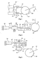
- two drive means 10, 12 are provided in the form of electric motors.
- the drive device 10, 12 also serve to actuate a joint 14, or a finger element 16 connected to the joint 14.
- the two motors 10, 12 each have a transmission element 18 and 20, respectively.
- the transmission elements 18, 20 may be cables, for example.
- the transmission elements 18, 20 are then each connected to a stiffness adjustment element 22 in the form of a spiral or helical spring with a non-linear characteristic.
- the stiffness adjusting element is in a particularly preferred embodiment, a rubber ball made of a suitable material, in particular elastomer.
- joint 14 may also be provided an intermediate element, such as a roller, to which a cable according to a human tendon is attached.
- a cable according to a human tendon By operating the motors 10, 12 takes place, for example, a winding a cable. Since this is connected according to a human tendon with a finger element, this may possibly cause the pivoting of a finger element.
- this pulse can be intercepted depending on the set stiffness of the stiffness adjustment elements 22. Damage to individual components of the robot hand, in particular the drive, is thus avoided.
- the finger element 16 is also connected to a hinge 14.
- the joint 14 is connected to a particularly stiff transmission element 36.
- the transmission element 36 is connected via an intermediate or transmission element 38 with the two spring elements 22.
- the intermediate element between the two spring elements 22 is connected.
- the intermediate element is arranged between the two spring elements 22, so that the connection between intermediate element 38 and transmission element 36 takes place between the two spring elements 22.
- the two spring elements 22 in turn have a non-linear characteristic.
- This in Fig. 2 right spring element 22 is fixed on one side 40.
- the other side 42 is connected to the intermediate element 38.
- the second spring element 22 is connected to the intermediate element 38 on the first side 40 and to a drive device, such as a motor 44, on the second side 42.
- the motor 44 is in Direction of an arrow 46, ie slidably mounted in the longitudinal direction of the stiffness adjustment elements 22.
- a connecting element 48 is the motor 44 is connected to a stationary motor 50.
- the stationary motor 50 By operating the stationary motor 50, the motor can be displaced in the direction of an arrow 46.
- the rigidity is adjusted by elongation / shortening of the second spring element 22.
- the pivoting of the joint 14 is effected by the motor 50, wherein in this case both the motor 44 and the second spring element 22 is moved.
- the finger element 16 is in turn connected to a joint 14. Via a transmission element 52, the joint 14 is connected to a motor 44. By operating the motor 44, the finger element 16 is moved in the direction of the arrow 28.
- the motor 44 itself is displaceably mounted in the direction of an arrow 46 via a bearing 54.
- the motor 44 is connected via an intermediate element 56 with an intermediate element 38.
- the intermediate element 38 is connected to the two spring elements 22, wherein the in Fig. 3 right end 40 of the spring element 22 is stationary, that is connected to a part of the robot hand.
- the right end 40 of the spring element 22 may also be displaceably mounted.
- the motor 50 is arranged stationary.
- the motor 50 is according to the third embodiment with an end 42 of in Fig. 3 connected to the left spring.
Landscapes
- Engineering & Computer Science (AREA)
- Robotics (AREA)
- Mechanical Engineering (AREA)
- Manipulator (AREA)
Claims (7)
- Main de robot comprenant
plusieurs doigts avec au moins deux éléments de doigt (16),
un élément de paume relié aux doigts,
des joints (14) disposés entre les éléments de doigt (16) aussi qu'entre l'élément de paume et les premiers éléments de doigt (16), et
des moyens d'entraînement (44, 50) reliés audits éléments de doigt (16) et/ou audits joints (14),
au moins un moyen d'entraînement (44, 50) étant relié à un élément d'ajustage de rigidité (22, 50, 44) pour ajuster la rigidité passive du joint (14),
caractérisée en ce que
deux moyens d'entraînement (44, 50) sont prévus, l'un des moyens d'entraînement (50) étant stationnaire et l'autre moyen d'entraînement (44) étant déplaçable, et un des moyens d'entraînement (44, 50) étant prévu pour l'ajustage de la rigidité tandis que l'autre moyen d'entraînement (50, 44) est prévu pour mouvoir l'élément de doigt (16). - Main de robot selon la revendication 1, caractérisée en ce que la rigidité de l'élément d'ajustage de rigidité (22, 44, 50) est ajustée par un changement en longueur, en particulier dans la direction) de transmission de force (32).
- Main de robot selon une des revendications 1 ou 2, caractérisée en ce que l'élément d'ajustage de rigidité (22, 44, 50)est relié à un moyen d'entraînement (50, 44), en particulier pour le changement de la longueur.
- Main de robot selon la revendication 3, caractérisée en ce que le moyen d'entraînement (50, 44) pour mouvoir de l'élément de doigt sert en outre à opérer les joints (14).
- Main de robot selon une des revendications 1 à 4, caractérisée en ce que deux éléments d'ajustage de rigidité (22) sont disposés l'un derrière l'autre.
- Main de robot selon la revendication 5, caractérisée en ce qu'un élément de transmission (36), relié audit joint (14) ou audit élément de doigt (16), est disposé entre les deux moyens d'ajustage de rigidité (22).
- Main de robot selon une des revendications 5 ou 6, caractérisée en ce que l'un (44) des deux moyens d'entraînement (44, 50) est disposé entre les deux éléments d'ajustage de rigidité (22).
Applications Claiming Priority (1)
| Application Number | Priority Date | Filing Date | Title |
|---|---|---|---|
| DE102006006322A DE102006006322B3 (de) | 2006-02-11 | 2006-02-11 | Roboterhand |
Publications (2)
| Publication Number | Publication Date |
|---|---|
| EP1820610A1 EP1820610A1 (fr) | 2007-08-22 |
| EP1820610B1 true EP1820610B1 (fr) | 2009-04-22 |
Family
ID=38109114
Family Applications (1)
| Application Number | Title | Priority Date | Filing Date |
|---|---|---|---|
| EP07101964A Not-in-force EP1820610B1 (fr) | 2006-02-11 | 2007-02-08 | Main de robot |
Country Status (3)
| Country | Link |
|---|---|
| EP (1) | EP1820610B1 (fr) |
| AT (1) | ATE429310T1 (fr) |
| DE (2) | DE102006006322B3 (fr) |
Families Citing this family (11)
| Publication number | Priority date | Publication date | Assignee | Title |
|---|---|---|---|---|
| US8276958B2 (en) | 2008-11-12 | 2012-10-02 | GM Global Technology Operations LLC | Bidirectional tendon terminator |
| US8562049B2 (en) * | 2009-09-22 | 2013-10-22 | GM Global Technology Operations LLC | Robotic finger assembly |
| DE102010033326B4 (de) * | 2010-08-04 | 2014-05-15 | Siemens Aktiengesellschaft | Roboter, insbesondere zur Ausführung einer medizinischen Behandlung |
| DE102011101206A1 (de) * | 2011-05-11 | 2012-11-15 | Fraunhofer-Gesellschaft zur Förderung der angewandten Forschung e.V. | Antriebssystem für einen Roboter oder eine Handhabungsvorrichtung sowie hiermit ausgestattete Roboter |
| DE102011105200B4 (de) * | 2011-06-17 | 2015-02-12 | Deutsches Zentrum für Luft- und Raumfahrt e.V. | Beinbasierter Roboter mit mindestens zwei Beinen |
| WO2015120083A1 (fr) | 2014-02-04 | 2015-08-13 | Rehabilitation Institute Of Chicago | Composants modulaires et légers de prothèse myoélectrique et procédés correspondants |
| CN105269589B (zh) * | 2014-07-02 | 2019-08-23 | 上海宇航系统工程研究所 | 一种空间机械臂模块化驱动关节 |
| DE102017204735B4 (de) | 2017-03-21 | 2019-04-25 | Deutsches Zentrum für Luft- und Raumfahrt e.V. | Robotergelenk |
| DE102018205303A1 (de) * | 2018-04-09 | 2019-10-10 | Deutsches Zentrum für Luft- und Raumfahrt e.V. | Antriebssystem für ein Instrument der minimalinvasiven Chirurgie |
| CN112676476A (zh) * | 2021-01-22 | 2021-04-20 | 仙居择栖农业机械有限公司 | 一种冲压生产电机配件的送料装置 |
| DE102023116652A1 (de) | 2023-06-23 | 2024-12-24 | Deutsches Zentrum für Luft- und Raumfahrt e.V. | Modulares Greiffingersystem, Greiffinger, modulares Greifersystem und Greifer für einen Roboter |
Family Cites Families (11)
| Publication number | Priority date | Publication date | Assignee | Title |
|---|---|---|---|---|
| US4865376A (en) * | 1987-09-25 | 1989-09-12 | Leaver Scott O | Mechanical fingers for dexterity and grasping |
| US5046375A (en) * | 1988-04-21 | 1991-09-10 | Massachusetts Institute Of Technology | Compact cable transmission with cable differential |
| US4946380A (en) * | 1989-05-30 | 1990-08-07 | University Of Southern California | Artificial dexterous hand |
| JPH0673828B2 (ja) * | 1989-12-22 | 1994-09-21 | 三菱重工業株式会社 | 人間形ロボット指機構の制御方法 |
| JPH068178A (ja) * | 1991-11-25 | 1994-01-18 | Toshiba Corp | ワイヤ駆動多関節装置 |
| JPH066953A (ja) * | 1992-06-18 | 1994-01-14 | Fuji Electric Co Ltd | 電動回転機械 |
| US5502363A (en) * | 1994-01-04 | 1996-03-26 | University Of Maryland-Baltimore County | Apparatus for controlling angular positioning and stiffness modulations of joint of robotic manipulator |
| US5762390A (en) * | 1996-07-16 | 1998-06-09 | Universite Laval | Underactuated mechanical finger with return actuation |
| JP3486639B2 (ja) * | 1999-10-26 | 2004-01-13 | 株式会社テムザック | マニピュレータ |
| FR2832345B1 (fr) * | 2001-11-19 | 2003-12-19 | Commissariat Energie Atomique | Mecanisme articule comprenant un reducteur a cable utilisable dans un bras de robot |
| JP2004306224A (ja) * | 2003-04-09 | 2004-11-04 | Keio Gijuku | ロボットフィンガ、4指ロボットハンド、及び、5指ロボットハンド |
-
2006
- 2006-02-11 DE DE102006006322A patent/DE102006006322B3/de not_active Expired - Fee Related
-
2007
- 2007-02-08 EP EP07101964A patent/EP1820610B1/fr not_active Not-in-force
- 2007-02-08 DE DE502007000623T patent/DE502007000623D1/de active Active
- 2007-02-08 AT AT07101964T patent/ATE429310T1/de active
Also Published As
| Publication number | Publication date |
|---|---|
| DE502007000623D1 (de) | 2009-06-04 |
| ATE429310T1 (de) | 2009-05-15 |
| DE102006006322B3 (de) | 2007-06-28 |
| EP1820610A1 (fr) | 2007-08-22 |
Similar Documents
| Publication | Publication Date | Title |
|---|---|---|
| EP1820610B1 (fr) | Main de robot | |
| DE102018222312A1 (de) | Greifhand | |
| EP3071373B1 (fr) | Bras de robot | |
| DE69729928T2 (de) | Kopplungssystem für eine Steuerknüppeleinheit | |
| EP2903789B1 (fr) | Robot industriel | |
| EP2651609B1 (fr) | Dispositif de protection pour un dispositif de préhension d'un manipulateur, en particulier un robot manipulateur | |
| EP3352950B1 (fr) | Robot industriel | |
| DE102009018150A1 (de) | Roboterhand und Fingermechansimus | |
| DE10346271A1 (de) | Handflächenmechanismus für eine Roboterhand | |
| WO2011015189A1 (fr) | Robot parallèle | |
| DE102013009889A1 (de) | Greifer mit drei Greifbacken | |
| DE102007031412A1 (de) | Klemmvorrichtung | |
| DE102010063195B4 (de) | Greifeinrichtung für eine Handhabungsvorrichtung, insbesondere einen Handhabungsroboter | |
| DE102017124368A1 (de) | Vereinfachte Fahrzeugtür-Schaltervorrichtung mit großer Betätigungsfläche | |
| EP3010665B1 (fr) | Outil de pliage | |
| DE102013018842A1 (de) | Spannvorricntung mit zwei langhubigen Backen | |
| DE102016209639A1 (de) | Roboterhand | |
| DE102011109786A1 (de) | Antriebsvorrichtung | |
| DE10212879A1 (de) | Betätigungsmechanismus für eine Feststellbremse | |
| WO2001038047A2 (fr) | Bras de prehension ou de commande | |
| DE102019117506A1 (de) | Greifvorrichtung und Roboter | |
| EP1870617B1 (fr) | Dispositif d'actionnement pour une transmission d'un véhicule | |
| DE102011016666A1 (de) | Vorrichtung zum Betreiben eines Greif- oder Bewegungswerkzeugs durch einen elektrischen Stellantrieb | |
| DE102017220479B3 (de) | Greifvorrichtung | |
| DE102016215744A1 (de) | Industrieroboter |
Legal Events
| Date | Code | Title | Description |
|---|---|---|---|
| PUAI | Public reference made under article 153(3) epc to a published international application that has entered the european phase |
Free format text: ORIGINAL CODE: 0009012 |
|
| AK | Designated contracting states |
Kind code of ref document: A1 Designated state(s): AT BE BG CH CY CZ DE DK EE ES FI FR GB GR HU IE IS IT LI LT LU LV MC NL PL PT RO SE SI SK TR |
|
| AX | Request for extension of the european patent |
Extension state: AL BA HR MK YU |
|
| 17P | Request for examination filed |
Effective date: 20080220 |
|
| 17Q | First examination report despatched |
Effective date: 20080325 |
|
| AKX | Designation fees paid |
Designated state(s): AT BE BG CH CY CZ DE DK EE ES FI FR GB GR HU IE IS IT LI LT LU LV MC NL PL PT RO SE SI SK TR |
|
| GRAP | Despatch of communication of intention to grant a patent |
Free format text: ORIGINAL CODE: EPIDOSNIGR1 |
|
| GRAS | Grant fee paid |
Free format text: ORIGINAL CODE: EPIDOSNIGR3 |
|
| GRAA | (expected) grant |
Free format text: ORIGINAL CODE: 0009210 |
|
| AK | Designated contracting states |
Kind code of ref document: B1 Designated state(s): AT BE BG CH CY CZ DE DK EE ES FI FR GB GR HU IE IS IT LI LT LU LV MC NL PL PT RO SE SI SK TR |
|
| REG | Reference to a national code |
Ref country code: GB Ref legal event code: FG4D Free format text: NOT ENGLISH |
|
| REG | Reference to a national code |
Ref country code: CH Ref legal event code: EP |
|
| REG | Reference to a national code |
Ref country code: IE Ref legal event code: FG4D |
|
| REF | Corresponds to: |
Ref document number: 502007000623 Country of ref document: DE Date of ref document: 20090604 Kind code of ref document: P |
|
| NLV1 | Nl: lapsed or annulled due to failure to fulfill the requirements of art. 29p and 29m of the patents act | ||
| PG25 | Lapsed in a contracting state [announced via postgrant information from national office to epo] |
Ref country code: FI Free format text: LAPSE BECAUSE OF FAILURE TO SUBMIT A TRANSLATION OF THE DESCRIPTION OR TO PAY THE FEE WITHIN THE PRESCRIBED TIME-LIMIT Effective date: 20090422 Ref country code: PT Free format text: LAPSE BECAUSE OF FAILURE TO SUBMIT A TRANSLATION OF THE DESCRIPTION OR TO PAY THE FEE WITHIN THE PRESCRIBED TIME-LIMIT Effective date: 20090822 Ref country code: LT Free format text: LAPSE BECAUSE OF FAILURE TO SUBMIT A TRANSLATION OF THE DESCRIPTION OR TO PAY THE FEE WITHIN THE PRESCRIBED TIME-LIMIT Effective date: 20090422 Ref country code: ES Free format text: LAPSE BECAUSE OF FAILURE TO SUBMIT A TRANSLATION OF THE DESCRIPTION OR TO PAY THE FEE WITHIN THE PRESCRIBED TIME-LIMIT Effective date: 20090802 |
|
| PG25 | Lapsed in a contracting state [announced via postgrant information from national office to epo] |
Ref country code: PL Free format text: LAPSE BECAUSE OF FAILURE TO SUBMIT A TRANSLATION OF THE DESCRIPTION OR TO PAY THE FEE WITHIN THE PRESCRIBED TIME-LIMIT Effective date: 20090422 Ref country code: SE Free format text: LAPSE BECAUSE OF FAILURE TO SUBMIT A TRANSLATION OF THE DESCRIPTION OR TO PAY THE FEE WITHIN THE PRESCRIBED TIME-LIMIT Effective date: 20090722 Ref country code: SI Free format text: LAPSE BECAUSE OF FAILURE TO SUBMIT A TRANSLATION OF THE DESCRIPTION OR TO PAY THE FEE WITHIN THE PRESCRIBED TIME-LIMIT Effective date: 20090422 Ref country code: IS Free format text: LAPSE BECAUSE OF FAILURE TO SUBMIT A TRANSLATION OF THE DESCRIPTION OR TO PAY THE FEE WITHIN THE PRESCRIBED TIME-LIMIT Effective date: 20090822 Ref country code: NL Free format text: LAPSE BECAUSE OF FAILURE TO SUBMIT A TRANSLATION OF THE DESCRIPTION OR TO PAY THE FEE WITHIN THE PRESCRIBED TIME-LIMIT Effective date: 20090422 Ref country code: LV Free format text: LAPSE BECAUSE OF FAILURE TO SUBMIT A TRANSLATION OF THE DESCRIPTION OR TO PAY THE FEE WITHIN THE PRESCRIBED TIME-LIMIT Effective date: 20090422 |
|
| REG | Reference to a national code |
Ref country code: IE Ref legal event code: FD4D |
|
| PG25 | Lapsed in a contracting state [announced via postgrant information from national office to epo] |
Ref country code: RO Free format text: LAPSE BECAUSE OF FAILURE TO SUBMIT A TRANSLATION OF THE DESCRIPTION OR TO PAY THE FEE WITHIN THE PRESCRIBED TIME-LIMIT Effective date: 20090422 Ref country code: EE Free format text: LAPSE BECAUSE OF FAILURE TO SUBMIT A TRANSLATION OF THE DESCRIPTION OR TO PAY THE FEE WITHIN THE PRESCRIBED TIME-LIMIT Effective date: 20090422 Ref country code: CZ Free format text: LAPSE BECAUSE OF FAILURE TO SUBMIT A TRANSLATION OF THE DESCRIPTION OR TO PAY THE FEE WITHIN THE PRESCRIBED TIME-LIMIT Effective date: 20090422 Ref country code: IE Free format text: LAPSE BECAUSE OF FAILURE TO SUBMIT A TRANSLATION OF THE DESCRIPTION OR TO PAY THE FEE WITHIN THE PRESCRIBED TIME-LIMIT Effective date: 20090422 Ref country code: DK Free format text: LAPSE BECAUSE OF FAILURE TO SUBMIT A TRANSLATION OF THE DESCRIPTION OR TO PAY THE FEE WITHIN THE PRESCRIBED TIME-LIMIT Effective date: 20090422 |
|
| PG25 | Lapsed in a contracting state [announced via postgrant information from national office to epo] |
Ref country code: SK Free format text: LAPSE BECAUSE OF FAILURE TO SUBMIT A TRANSLATION OF THE DESCRIPTION OR TO PAY THE FEE WITHIN THE PRESCRIBED TIME-LIMIT Effective date: 20090422 |
|
| PLBE | No opposition filed within time limit |
Free format text: ORIGINAL CODE: 0009261 |
|
| STAA | Information on the status of an ep patent application or granted ep patent |
Free format text: STATUS: NO OPPOSITION FILED WITHIN TIME LIMIT |
|
| 26N | No opposition filed |
Effective date: 20100125 |
|
| PG25 | Lapsed in a contracting state [announced via postgrant information from national office to epo] |
Ref country code: BG Free format text: LAPSE BECAUSE OF FAILURE TO SUBMIT A TRANSLATION OF THE DESCRIPTION OR TO PAY THE FEE WITHIN THE PRESCRIBED TIME-LIMIT Effective date: 20090722 |
|
| BERE | Be: lapsed |
Owner name: DEUTSCHES ZENTRUM FUR LUFT- UND RAUMFAHRT E.V. Effective date: 20100228 |
|
| PG25 | Lapsed in a contracting state [announced via postgrant information from national office to epo] |
Ref country code: GR Free format text: LAPSE BECAUSE OF FAILURE TO SUBMIT A TRANSLATION OF THE DESCRIPTION OR TO PAY THE FEE WITHIN THE PRESCRIBED TIME-LIMIT Effective date: 20090723 Ref country code: MC Free format text: LAPSE BECAUSE OF NON-PAYMENT OF DUE FEES Effective date: 20100301 |
|
| PG25 | Lapsed in a contracting state [announced via postgrant information from national office to epo] |
Ref country code: BE Free format text: LAPSE BECAUSE OF NON-PAYMENT OF DUE FEES Effective date: 20100228 |
|
| PG25 | Lapsed in a contracting state [announced via postgrant information from national office to epo] |
Ref country code: IT Free format text: LAPSE BECAUSE OF FAILURE TO SUBMIT A TRANSLATION OF THE DESCRIPTION OR TO PAY THE FEE WITHIN THE PRESCRIBED TIME-LIMIT Effective date: 20090422 |
|
| REG | Reference to a national code |
Ref country code: CH Ref legal event code: PL |
|
| PG25 | Lapsed in a contracting state [announced via postgrant information from national office to epo] |
Ref country code: LI Free format text: LAPSE BECAUSE OF NON-PAYMENT OF DUE FEES Effective date: 20110228 Ref country code: CH Free format text: LAPSE BECAUSE OF NON-PAYMENT OF DUE FEES Effective date: 20110228 |
|
| PG25 | Lapsed in a contracting state [announced via postgrant information from national office to epo] |
Ref country code: CY Free format text: LAPSE BECAUSE OF FAILURE TO SUBMIT A TRANSLATION OF THE DESCRIPTION OR TO PAY THE FEE WITHIN THE PRESCRIBED TIME-LIMIT Effective date: 20090422 |
|
| PG25 | Lapsed in a contracting state [announced via postgrant information from national office to epo] |
Ref country code: LU Free format text: LAPSE BECAUSE OF NON-PAYMENT OF DUE FEES Effective date: 20100208 Ref country code: HU Free format text: LAPSE BECAUSE OF FAILURE TO SUBMIT A TRANSLATION OF THE DESCRIPTION OR TO PAY THE FEE WITHIN THE PRESCRIBED TIME-LIMIT Effective date: 20091023 |
|
| PG25 | Lapsed in a contracting state [announced via postgrant information from national office to epo] |
Ref country code: TR Free format text: LAPSE BECAUSE OF FAILURE TO SUBMIT A TRANSLATION OF THE DESCRIPTION OR TO PAY THE FEE WITHIN THE PRESCRIBED TIME-LIMIT Effective date: 20090422 |
|
| REG | Reference to a national code |
Ref country code: AT Ref legal event code: MM01 Ref document number: 429310 Country of ref document: AT Kind code of ref document: T Effective date: 20120208 |
|
| PG25 | Lapsed in a contracting state [announced via postgrant information from national office to epo] |
Ref country code: AT Free format text: LAPSE BECAUSE OF NON-PAYMENT OF DUE FEES Effective date: 20120208 |
|
| REG | Reference to a national code |
Ref country code: FR Ref legal event code: PLFP Year of fee payment: 10 |
|
| REG | Reference to a national code |
Ref country code: FR Ref legal event code: PLFP Year of fee payment: 11 |
|
| REG | Reference to a national code |
Ref country code: FR Ref legal event code: PLFP Year of fee payment: 12 |
|
| REG | Reference to a national code |
Ref country code: DE Ref legal event code: R084 Ref document number: 502007000623 Country of ref document: DE |
|
| PGFP | Annual fee paid to national office [announced via postgrant information from national office to epo] |
Ref country code: GB Payment date: 20200130 Year of fee payment: 14 Ref country code: DE Payment date: 20200115 Year of fee payment: 14 |
|
| PGFP | Annual fee paid to national office [announced via postgrant information from national office to epo] |
Ref country code: FR Payment date: 20200124 Year of fee payment: 14 |
|
| REG | Reference to a national code |
Ref country code: DE Ref legal event code: R119 Ref document number: 502007000623 Country of ref document: DE |
|
| GBPC | Gb: european patent ceased through non-payment of renewal fee |
Effective date: 20210208 |
|
| PG25 | Lapsed in a contracting state [announced via postgrant information from national office to epo] |
Ref country code: GB Free format text: LAPSE BECAUSE OF NON-PAYMENT OF DUE FEES Effective date: 20210208 Ref country code: FR Free format text: LAPSE BECAUSE OF NON-PAYMENT OF DUE FEES Effective date: 20210228 Ref country code: DE Free format text: LAPSE BECAUSE OF NON-PAYMENT OF DUE FEES Effective date: 20210901 |