EP1820633B1 - Procédé et appareil pour prendre des éléments tubulaires aplatis depuis un magasin et pour les déplacer vers une station de mise en volume - Google Patents
Procédé et appareil pour prendre des éléments tubulaires aplatis depuis un magasin et pour les déplacer vers une station de mise en volume Download PDFInfo
- Publication number
- EP1820633B1 EP1820633B1 EP07102326A EP07102326A EP1820633B1 EP 1820633 B1 EP1820633 B1 EP 1820633B1 EP 07102326 A EP07102326 A EP 07102326A EP 07102326 A EP07102326 A EP 07102326A EP 1820633 B1 EP1820633 B1 EP 1820633B1
- Authority
- EP
- European Patent Office
- Prior art keywords
- blank
- magazine
- axis
- arm
- flat folded
- Prior art date
- Legal status (The legal status is an assumption and is not a legal conclusion. Google has not performed a legal analysis and makes no representation as to the accuracy of the status listed.)
- Not-in-force
Links
- 238000000034 method Methods 0.000 title claims description 15
- 230000033001 locomotion Effects 0.000 claims description 14
- 230000005540 biological transmission Effects 0.000 claims description 13
- 230000007246 mechanism Effects 0.000 claims description 6
- 230000009471 action Effects 0.000 claims description 4
- 230000004913 activation Effects 0.000 claims 2
- 230000008859 change Effects 0.000 description 5
- 238000004519 manufacturing process Methods 0.000 description 3
- 239000002537 cosmetic Substances 0.000 description 2
- 238000000151 deposition Methods 0.000 description 2
- 238000012423 maintenance Methods 0.000 description 2
- 239000011236 particulate material Substances 0.000 description 2
- 230000002547 anomalous effect Effects 0.000 description 1
- 230000008901 benefit Effects 0.000 description 1
- 238000010276 construction Methods 0.000 description 1
- 230000009849 deactivation Effects 0.000 description 1
- 230000002028 premature Effects 0.000 description 1
- 230000008569 process Effects 0.000 description 1
- 238000004804 winding Methods 0.000 description 1
Images




Classifications
-
- B—PERFORMING OPERATIONS; TRANSPORTING
- B65—CONVEYING; PACKING; STORING; HANDLING THIN OR FILAMENTARY MATERIAL
- B65B—MACHINES, APPARATUS OR DEVICES FOR, OR METHODS OF, PACKAGING ARTICLES OR MATERIALS; UNPACKING
- B65B43/00—Forming, feeding, opening or setting-up containers or receptacles in association with packaging
- B65B43/26—Opening or distending bags; Opening, erecting, or setting-up boxes, cartons, or carton blanks
- B65B43/30—Opening or distending bags; Opening, erecting, or setting-up boxes, cartons, or carton blanks by grippers engaging opposed walls, e.g. suction-operated
- B65B43/305—Opening or distending bags; Opening, erecting, or setting-up boxes, cartons, or carton blanks by grippers engaging opposed walls, e.g. suction-operated specially adapted for boxes, cartons or carton blanks
-
- B—PERFORMING OPERATIONS; TRANSPORTING
- B65—CONVEYING; PACKING; STORING; HANDLING THIN OR FILAMENTARY MATERIAL
- B65H—HANDLING THIN OR FILAMENTARY MATERIAL, e.g. SHEETS, WEBS, CABLES
- B65H3/00—Separating articles from piles
- B65H3/08—Separating articles from piles using pneumatic force
- B65H3/0808—Suction grippers
- B65H3/085—Suction grippers separating from the bottom of pile
-
- B—PERFORMING OPERATIONS; TRANSPORTING
- B65—CONVEYING; PACKING; STORING; HANDLING THIN OR FILAMENTARY MATERIAL
- B65H—HANDLING THIN OR FILAMENTARY MATERIAL, e.g. SHEETS, WEBS, CABLES
- B65H3/00—Separating articles from piles
- B65H3/08—Separating articles from piles using pneumatic force
- B65H3/0808—Suction grippers
- B65H3/0883—Construction of suction grippers or their holding devices
-
- B—PERFORMING OPERATIONS; TRANSPORTING
- B31—MAKING ARTICLES OF PAPER, CARDBOARD OR MATERIAL WORKED IN A MANNER ANALOGOUS TO PAPER; WORKING PAPER, CARDBOARD OR MATERIAL WORKED IN A MANNER ANALOGOUS TO PAPER
- B31B—MAKING CONTAINERS OF PAPER, CARDBOARD OR MATERIAL WORKED IN A MANNER ANALOGOUS TO PAPER
- B31B2100/00—Rigid or semi-rigid containers made by folding single-piece sheets, blanks or webs
-
- B—PERFORMING OPERATIONS; TRANSPORTING
- B31—MAKING ARTICLES OF PAPER, CARDBOARD OR MATERIAL WORKED IN A MANNER ANALOGOUS TO PAPER; WORKING PAPER, CARDBOARD OR MATERIAL WORKED IN A MANNER ANALOGOUS TO PAPER
- B31B—MAKING CONTAINERS OF PAPER, CARDBOARD OR MATERIAL WORKED IN A MANNER ANALOGOUS TO PAPER
- B31B2100/00—Rigid or semi-rigid containers made by folding single-piece sheets, blanks or webs
- B31B2100/002—Rigid or semi-rigid containers made by folding single-piece sheets, blanks or webs characterised by the shape of the blank from which they are formed
- B31B2100/0024—Rigid or semi-rigid containers made by folding single-piece sheets, blanks or webs characterised by the shape of the blank from which they are formed having all side walls attached to the bottom
-
- B—PERFORMING OPERATIONS; TRANSPORTING
- B31—MAKING ARTICLES OF PAPER, CARDBOARD OR MATERIAL WORKED IN A MANNER ANALOGOUS TO PAPER; WORKING PAPER, CARDBOARD OR MATERIAL WORKED IN A MANNER ANALOGOUS TO PAPER
- B31B—MAKING CONTAINERS OF PAPER, CARDBOARD OR MATERIAL WORKED IN A MANNER ANALOGOUS TO PAPER
- B31B2120/00—Construction of rigid or semi-rigid containers
- B31B2120/30—Construction of rigid or semi-rigid containers collapsible; temporarily collapsed during manufacturing
-
- B—PERFORMING OPERATIONS; TRANSPORTING
- B31—MAKING ARTICLES OF PAPER, CARDBOARD OR MATERIAL WORKED IN A MANNER ANALOGOUS TO PAPER; WORKING PAPER, CARDBOARD OR MATERIAL WORKED IN A MANNER ANALOGOUS TO PAPER
- B31B—MAKING CONTAINERS OF PAPER, CARDBOARD OR MATERIAL WORKED IN A MANNER ANALOGOUS TO PAPER
- B31B50/00—Making rigid or semi-rigid containers, e.g. boxes or cartons
- B31B50/02—Feeding or positioning sheets, blanks or webs
- B31B50/04—Feeding sheets or blanks
- B31B50/06—Feeding sheets or blanks from stacks
- B31B50/062—Feeding sheets or blanks from stacks from the underside of a magazine
-
- B—PERFORMING OPERATIONS; TRANSPORTING
- B31—MAKING ARTICLES OF PAPER, CARDBOARD OR MATERIAL WORKED IN A MANNER ANALOGOUS TO PAPER; WORKING PAPER, CARDBOARD OR MATERIAL WORKED IN A MANNER ANALOGOUS TO PAPER
- B31B—MAKING CONTAINERS OF PAPER, CARDBOARD OR MATERIAL WORKED IN A MANNER ANALOGOUS TO PAPER
- B31B50/00—Making rigid or semi-rigid containers, e.g. boxes or cartons
- B31B50/74—Auxiliary operations
- B31B50/76—Opening and distending flattened articles
- B31B50/80—Pneumatically
-
- B—PERFORMING OPERATIONS; TRANSPORTING
- B31—MAKING ARTICLES OF PAPER, CARDBOARD OR MATERIAL WORKED IN A MANNER ANALOGOUS TO PAPER; WORKING PAPER, CARDBOARD OR MATERIAL WORKED IN A MANNER ANALOGOUS TO PAPER
- B31B—MAKING CONTAINERS OF PAPER, CARDBOARD OR MATERIAL WORKED IN A MANNER ANALOGOUS TO PAPER
- B31B50/00—Making rigid or semi-rigid containers, e.g. boxes or cartons
- B31B50/74—Auxiliary operations
- B31B50/76—Opening and distending flattened articles
- B31B50/80—Pneumatically
- B31B50/804—Pneumatically using two or more suction devices on a rotating element
-
- B—PERFORMING OPERATIONS; TRANSPORTING
- B65—CONVEYING; PACKING; STORING; HANDLING THIN OR FILAMENTARY MATERIAL
- B65H—HANDLING THIN OR FILAMENTARY MATERIAL, e.g. SHEETS, WEBS, CABLES
- B65H2555/00—Actuating means
- B65H2555/30—Multi-axis
-
- B—PERFORMING OPERATIONS; TRANSPORTING
- B65—CONVEYING; PACKING; STORING; HANDLING THIN OR FILAMENTARY MATERIAL
- B65H—HANDLING THIN OR FILAMENTARY MATERIAL, e.g. SHEETS, WEBS, CABLES
- B65H2701/00—Handled material; Storage means
- B65H2701/10—Handled articles or webs
- B65H2701/17—Nature of material
- B65H2701/176—Cardboard
- B65H2701/1766—Cut-out, multi-layer, e.g. folded blanks or boxes
Definitions
- the present invention relates to boxing machines, aimed particularly at picking up flat folded tubular blanks from a magazine, at erecting them with the axis oriented vertically and at filling them along the same direction, with articles of various kinds, such as bottles.
- the invention relates to an apparatus, being an integral part of a boxing machine, and a related method for picking up flat folded tubular blanks from an open and inclined bottom of a magazine and for their transfer to an erecting station.
- tubular blank indicates an object made of cardboard or Bristol board, in which two opposite sheets touch each other and are connected at two opposite ends, so as to define just a flat configuration.
- the blank has also longitudinal creasing lines, which facilitate blank folding in order to make it assume a substantially parallelepiped shape, and transversal creasing lines, which facilitate folding of the flaps in order to close the blank bottom and cover.
- the boxes are usually made of light cardboard and the tubular blanks for making them have each one three flaps at each end, two of which are opposite and have the same shape, while the remainder has larger dimension and is defined by a tab for closing the corresponding end.
- the boxes are preferably loaded inside magazines having outlet sections inclined or vertical, so that only one of the ends connecting the two sheets defining a case or a box acts as a support element.
- a similar arrangement of flat folded tubular blanks inside the magazine can cause a premature, undesired and uncontrolled folding of the flaps of one or more blanks, thus provoking its incorrect withdrawing from the outlet section of the magazine and consequently its rejection, or else machine downtimes, with all the negative consequences that can result therefrom.
- the document EP 447.375 describes a device associated to a line including at least two identical chains, winding endlessly and laying on horizontal planes, moved with the same speed and having radial prongs, which are oriented outwards and thus defining a series of vertical seats; and a magazine containing a pile of blanks in flat folded configuration.
- First means pick up a blank from the pile and place it horizontally in an intermediate station, where second means, acting in time relation with the first ones, grip the blank, which is moved, so that its axis passes progressively from the horizontal orientation to the vertical one.
- the blank is also made to rotate with respect to its axis, so that it strikes first a stationary abutment, which partially erects the blank, and subsequently the prongs of a corresponding vertical seat, with a velocity component contrary to the prongs translation direction, so that the prongs complete the blank erecting.
- the primary object of the present invention is to propose an apparatus and a method, which describes its annexed work steps, aimed at being a part of a vertical acting boxing machine, as well as at picking up flat folded tubular blanks from the open inclined bottom of a magazine and at their transfer to an erecting station with the axis oriented vertically.
- the above mentioned object is to be obtained by a sequence of essential work steps, which can be carried out by the above mentioned apparatus without any interference with the regular operation of the whole boxing machine.
- Another object of the present invention is to propose a method, which can lead to high production rate at relatively low costs with respect to prior art.
- a further object of the invention is to propose a newly conceived apparatus for picking up flat folded tubular blanks from the open, inclined bottom of a magazine and for moving them to an erecting station, said apparatus having essential structure and being reliable, highly productive and relatively cheap with respect to the results to be obtained.
- a still further object of the invention is to propose an apparatus, and a related method, which is capable of moving said blanks to an erecting station, situated at a certain distance from the longitudinal extension plane of the magazine.
- the reference numeral 1 indicates a magazine of known type, e.g. having a bottom 1a open and inclined, only the terminal, inclined part of which is shown schematically ( Figures 1, 2 ), and inside which a plurality of tubular blanks 2 in flat folded configuration are piled up.
- each tubular blank 2 two facing sheets can be defined, which are connected to each other along two opposite ends 2k, 2z, so as to define flat folded configuration 2w.
- Each blank 2 has longitudinal creasing lines aimed at facilitating its folding, so as to assume parallelepiped shape, and transversal creasing lines aimed at facilitating folding of related flaps.
- tubular blanks 2 form corresponding boxes of light cardboard, having a selected flexibility, therefore only one of the above mentioned connection ends 2k, 2z, turned downwards, is loaded into the magazine 1, for the reasons already discussed in the introductory note.
- the reference numeral 10 indicates generically the apparatus proposed by the invention, aimed at working between a station P for picking up a flat folded tubular blank 2 from the open, inclined bottom 1a of the magazine 1, shown in Figures 1, 2 , and an erecting station MV, where the same blank 2 arrives in vertical position, due to a combined rotation-translation movement, as it will appear in the following.
- the apparatus 10 includes a plurality of functional elements, which will be described later.
- a horizontal shaft 3 for transmission of the rotation movement has the axis parallel to the opposite, lower and upper edges of the open, inclined bottom of the magazine 1.
- the shaft 3 is operated by first actuating means, not shown, as of conventional type, and situated beside and below the bottom 1a of the magazine 1 ( Figures 1, 2 ).
- the end of the shaft 3 forms, in axial direction, a projection 3h, whose functional characteristics will be discussed in the following.
- the shaft 3 is carried, with possibility to rotate, by a cylindrical jacket 4, which ends with a base 4h, through which the projection 3h protrudes. (the projection 3h is the only part of the transmission shaft 3 seen in the Figures)
- a functional arm 5 is hinged on one side to the projection 3h of the transmission shaft 3 about a first articulation axis A1, perpendicular to the shaft 3 axis (see Figures for example 2, 5, 5A), so as to receive the rotational motion transmitted by the same shaft 3.
- the functional arm 5 is hinged to an mechanism 6,8 for controlling the arrangement, which will be discussed later in the description, about a second articulation axis A2, orthogonal to the first axis A1.
- the functional arm 5 is so operated as to oscillate about the first articulation axis A1, by second actuating means, not shown as known, between an alignment position AL and a square position S, and vice versa.
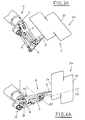
- the longitudinal axis of the functional arm 5 in the alignment position, is in alignment with the transmission shaft 3 ( Figures 1 , 1A , 2 , 2A ), whereas in the square position forms a 90 degrees angle ( Figures 4 , 4A , 4B, 4C ) with respect to the rotation axis of the transmission shaft 3.
- the functional arm 5 is operated by the second actuating means through a stem 7, coupled by means of a ball joint to a relative protuberance 5h extending from the arm 5.
- the above mentioned arrangement control mechanism includes a plate 6 and a tie rod 8 coupled to each other by means of ball joints; the plate 6 is articulated with a relevant central portion to the functional arm 5, about the second articulation axis A2.
- the outer parts of the plate 6 are respectively coupled by the above mentioned ball joint to the end of the tie rod 8 and fastened to a pick up arm 9, elements that will be described later.
- the other end of the tie rod 8 is coupled by means of a ball joint with a turret 4k, which extends from the base 4h of the jacket 4 parallel to the axis of the transmission shaft 3; the turret can rotate about a relevant axis (See figures 3 and 4 ).
- the gripping means 11 include four suction cups 11h connected to a suction source, not shown.
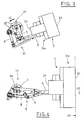
- Figure 1 shows the station P and the related picking up of a flat folded tubular blank 2 from the open, inclined bottom 1a of the magazine 1, by the pick up arm 9 and after setting the suction cups 11h to perform the suction action.
- the functional arm 5 is in the alignment position AL, while the longitudinal axis of the pick up arm 9 forms an angle of about 90 degrees with respect to the functional arm 5.
- the longitudinal axis of the arm 9 is parallel to the bottom 1a, that is to the flat folded profile of the blank 2, in order to allow an optimal gripping of the blank by the suction cups 11h; such position in consequent to the consistent rotation of the shaft 3.
- the first and the second actuating means are operated in mutual time relation, which determines the simultaneous rotation of the transmission shaft 3 in the direction J2 (counterclockwise according to the view of Figure 3 ), the downward rotation of the functional arm 5 and the rotation of the plate 6 - pick up arm 9 group with respect to the second articulation axis A2 ( Figures 3 , 3A ).
- This particular movement is caused by the tie rod 8, which can move due to the presence of the ball joints provided at its ends, ad by the motion of the turret 4K.
- the functional arm 5 is in the square position S with respect to the shaft 3, the above mentioned group is substantially aligned with the functional arm and the flat folded tubular blank 2 is in the erection station MV, in which it has a vertical orientation.
- tie rod 8 The dimensions of the tie rod 8 and its functional interposition between the turret 4k and the plate 6 are so designed, obviously bearing in mind other elements of the apparatus 10, as to allow an optimal picking up step of the blank 2 (see above) and the arrangement of the last in the station MV with its axis vertical.
- the flat folded tubular blank 2 situated in horizontal configuration below the magazine 1 is moved by the apparatus 10 to the erecting station MV with a combined motion of translation and rotation by an angle of 90° with respect to an axis parallel to the related transversal creasing lines, as it appears from the top view of Figure 4C , in which the blank 2 is shown in horizontal orientation, with broken line, as well as in the vertical one in the station MV, with continuous line.
- the erecting station MV is external with respect to the space occupied by the magazine 1 and anyway, not aligned with it.
- Figures 4B, 4C show for example means 12, non belonging to the apparatus 10, situated in the erecting station MV and aimed at erecting the flat folded tubular blank 2.
- the means 12 are pivoted with respect to a vertical axis and carry suction cups 12h connected to a vacuum source, not shown.
- the means 12 are moved on a vertical axis by third actuating means, likewise not shown, between a gripping position, indicated with broken line ( Figure 4B ), in which the suction cups 12h are operated to grip a second lateral wall of the flat folded tubular blank 2, adjacent to the first lateral wall, likewise subjected to the gripping action of the suction means 11, and an open position, indicated with continuous line ( Figure 4B, 4C ), which causes the rotation of the second lateral wall of the blank 2 by 90° with respect to the first wall, thus erecting the blank 2 and making it assume a parallelepiped shape ( Figure 4C ).
- the active step of the cycle performed by the apparatus 10 ends when the flat folded tubular blank 2, with its axis oriented vertically, reaches the erecting station MV.
- the active step of the cycle is followed by the inactive one, that is the deactivation of the suction cups 11h and the repetition of the above described operations, substantially backwards (as shown in Figures 5 , 5A , 6 , 6A ,), which allow the disengagement of the blank 2 without jeopardizing or slowing down the subsequent processes to which the blank must be subjected (e.g. keeping the blank 2 squared and its vertical filling with articles such as cosmetic products, bottles or similar).
- the apparatus 10 proposed by the invention is considerably flexible in relation to the size change requirements: in the magazines 1, in which the flat folded tubular blanks 2 are loaded with the upper connecting end 2z always aligned with a fixed plane (e.g. parallel to the same upper wall of the magazine 1), the operator must only carry out the necessary adjustments in the magazine 1 and, possibly, remove the two suction cups 11h closest to the pick up arm 9 if, e.g. the new production requires the use of smaller boxes.
- each tubular blank 2 regardless of its dimensions, reaches the erecting station MV with the outermost connecting end 2z always aligned with respect to a fixed vertical axis H1 ( Figures 4B, 4C ), in this particular case coinciding with the articulation axis of the means 12.
- a fixed alignment axis H1 is advantageous in general terms, because it can simplify, as in the shown example, the adjustment operations during the blanks size change, performed by the means aimed at the blanks erecting.
- the flat folded tubular blanks 2 arrive at the erecting station MV with the lower transversal creasing line always aligned with respect to a fixed horizontal axis H2, regardless of the size change.
- the apparatus 10 for picking up flat folded tubular blanks 2 from the magazine 1 and for their moving to the erecting station MV includes, as follows and in a cyclical way:
- the blank 2 after having been gripped and rotated to assume a horizontal orientation, is moved toward the erecting station MV with a combined motion, in which its translation and rotation by a 90° angle with respect to an axis parallel to the related transversal creasing lines are performed at the same time.
- the present invention proposes by an apparatus for picking up flat folded tubular blanks from the open, inclined bottom of a magazine and for their movement to the erecting station MV, with a vertical orientation and with the related axis arranged vertically.
- the present apparatus integrates in optimal way with the boxing machines with vertical loading, aimed at vertical introducing of various articles, such as cosmetic products, bottles and similar into the erected boxes.
- the magazine proposed in the shown example has in this specific case, an open inclined bottom, however, other types of magazines are not excluded, such as magazines with vertical and not inclined outlet section, which can be likewise easily integrated with the proposed apparatus.
- the magazine 1 and the erecting station MV are at comparable levels: this allows the magazine 1 to be arranged in a particularly easy way for the operator to load the flat folded tubular blanks 2.
- the proposed invention fully satisfies the prefixed objects: the construction of the apparatus is essential, the apparatus is reliable, ensures high production rate and relatively low costs with respect to the obtained results.
- the relative method includes a plurality of fundamental work steps, whose carrying out by the above mentioned apparatus does not interfere with the regular operation of the whole boxing machine.
Landscapes
- Engineering & Computer Science (AREA)
- Mechanical Engineering (AREA)
- Supplying Of Containers To The Packaging Station (AREA)
- Making Paper Articles (AREA)
- Folding Of Thin Sheet-Like Materials, Special Discharging Devices, And Others (AREA)
- Perforating, Stamping-Out Or Severing By Means Other Than Cutting (AREA)
- Warehouses Or Storage Devices (AREA)
Claims (16)
- Un appareil pour prélever des découpes tubulaires à plat d'un magasin et pour déplacer les découpes vers une station de mise en volume, chaque découpe tubulaire desdites découpes tubulaires (2) étant définie par deux feuilles se faisant face et raccordées l'une à l'autre au niveau de deux extrémités opposées (2k, 2z), de manière à définir une configuration à plat (2w), ladite découpe (2) ayant des lignes de pliage longitudinales pour faciliter le pliage, afin qu'une boîte ainsi obtenue prenne une forme essentiellement parallélépipédique, et des lignes de pliage transversales pour faciliter le pliage de rabats correspondants de ladite découpe (2), et avec ledit magasin (1) ayant un fond ouvert (1a) pour prélever une à une les découpes tubulaires à plat (2) susmentionnées, avec une extrémité des deux extrémités (2k, 2z) de raccordement orientée vers le bas, caractérisé en ce qu'il comprend :un arbre horizontal (3) de transmission du mouvement de rotation, ayant un axe parallèle à des bords opposés, inférieur et supérieur, du fond ouvert dudit magasin (1), ledit arbre (3) étant actionné par des premiers moyens d'actionnement et situé à côté dudit fond ouvert (1a) dudit magasin (1) ;un bras fonctionnel (5) articulé d'un côté à une projection (3h) dudit arbre de transmission (3) autour d'un premier axe d'articulation (A1), perpendiculaire à l'arbre (3), de manière à recevoir le mouvement transmis par ledit arbre (3), et ledit bras fonctionnel (5) étant articulé de l'autre côté à un mécanisme de contrôle de l'assiette (6, 8) au niveau d'un deuxième axe d'articulation (A2), orthogonal audit premier axe d'articulation (A1), ledit bras fonctionnel (5) étant également actionné, par des deuxièmes moyens d'actionnement, pour tourner sur ledit premier axe d'articulation (A1) en relation de phase avec l'activation desdits premiers moyens, entre une position d'alignement (AL) et une position en équerre (S), et inversement, dans lesquelles l'axe longitudinal dudit bras fonctionnel (5) est respectivement aligné avec, et forme un angle de 90 degrés par rapport à l'axe de rotation dudit arbre de transmission (3) ;un bras de prélèvement (9), fixé audit mécanisme de contrôle de l'assiette (6, 8), qui porte des moyens (11) destinés à prélever une découpe tubulaire à plat (2) du fond ouvert (1a) dudit magasin (1) ;ledit mécanisme de contrôle de l'assiette (6, 8) étant actionné en relation de phase adéquate avec l'activation desdits premiers et deuxièmes moyens d'actionnement, pour mouvoir, en association avec ces derniers, ledit appareil (10) entre une station (P) pour prélever une découpe tubulaire à plat (2) à travers le fond ouvert (1a) dudit magasin (1), dans laquelle ledit bras fonctionnel (5) est dans la position d'alignement (AL) et ledit bras de prélèvement (9) a son axe longitudinal parallèle au fond ouvert (1a) dudit magasin (1), et une station de mise en volume (MV) pour mettre en volume la découpe tubulaire (2), dans laquelle ledit bras fonctionnel (5) est dans la position en équerre (S) et la découpe tubulaire (2) a son axe disposé verticalement, et inversement.
- L'appareil selon la revendication 1, caractérisé en
ce que ledit mécanisme de contrôle de l'assiette comprend :une plaque (6) avec une partie centrale articulée audit bras fonctionnel (5) au niveau dudit deuxième axe d'articulation (A2), ladite plaque étant accouplée d'un côté avec ledit bras de prélèvement (9) ;un tirant (8) ayant une extrémité reliée, au moyen d'une articulation sphérique, à un côté de ladite plaque (6) opposé audit côté de la plaque qui est accouplé avec ledit bras de prélèvement (9), et une extrémité reliée, au moyen d'une autre articulation sphérique, à une tourelle (4K), tournant autour d'un axe de rotation parallèle à l'arbre de transmission (3). - L'appareil selon la revendication 1, caractérisé en
ce que l'axe longitudinal dudit bras fonctionnel (5), dans ladite position en équerre (S), est essentiellement horizontal. - L'appareil selon la revendication 1, caractérisé en
ce que l'axe longitudinal dudit bras fonctionnel (5), dans ladite position en équerre (S), est essentiellement horizontal et aligné avec l'axe longitudinal dudit bras de prélèvement (9). - L'appareil selon la revendication 1, caractérisé en
ce que ledit bras de prélèvement (9) est perpendiculaire à l'axe longitudinal dudit bras fonctionnel (5) pendant le prélèvement, dans la station (P) correspondante, d'une découpe tubulaire à plat (2) du fond ouvert (1a) dudit magasin (1). - L'appareil selon la revendication 1, caractérisé en
ce que ledit appareil (10) coopère fonctionnellement, dans ladite station de mise en volume (MV), avec des moyens (12) pour la mise en volume de chaque découpe tubulaire (2). - L'appareil selon la revendication 1, caractérisé en
ce que ledit bras fonctionnel (5) est accouplé, au moyen d'une articulation sphérique, avec une tige (7), actionnée par les mêmes deuxièmes moyens d'actionnement qui actionnent le bras fonctionnel (5). - L'appareil selon la revendication 1 ou 5,
caractérisé en ce que le fond ouvert (1a) dudit magasin (1) est également incliné. - L'appareil selon la revendication 1, caractérisé en
ce que ledit arbre de transmission (3) est également situé à un niveau inférieur par rapport au fond ouvert (1a) dudit magasin (1). - Un procédé pour prélever des découpes tubulaires à plat d'un magasin et pour déplacer les découpes vers une station de mise en volume, chaque découpe tubulaire desdites découpes tubulaires (2) étant définie par deux feuilles se faisant face et raccordées l'une à l'autre au niveau de deux extrémités opposées (2k, 2z), de manière à définir une configuration à plat (2w), ladite découpe (2) ayant des lignes de pliage longitudinales pour un pliage facile, afin de prendre une forme essentiellement parallélépipédique, et des lignes de pliage transversales pour plier facilement, à leur tour, des rabats correspondants de ladite découpe (2), et avec ledit magasin (1) ayant un fond ouvert (1a) à travers lequel les découpes tubulaires à plat (2) susmentionnées sont prélevées une à une, avec une des deux extrémités (2k, 2z) de raccordement orientée vers le bas, caractérisé en ce qu'il comprend comme suit et de façon cyclique :- le prélèvement d'une découpe tubulaire à plat (2) à travers le fond ouvert (1a) dudit magasin (1), par assujettissement d'une première paroi latérale de la découpe, orientée vers l'extérieur par rapport au magasin, et par rotation vers le bas de la découpe (2) pour que ladite découpe prenne une orientation horizontale ;- le déplacement de la découpe (2) assujettie vers une station de mise en volume (MV), par un mouvement combiné de translation et de rotation de 90 degrés par rapport à un axe parallèle aux lignes de pliage transversales de la découpe (2), de manière à ce que la découpe prenne, dans ladite station de mise en volume (MV), une orientation verticale, avec son axe orienté verticalement.
- Le procédé selon la revendication 10, caractérisé en ce que la translation et la rotation de la découpe de 90 degrés par rapport à un axe parallèle aux lignes de pliage transversales de celle-ci sont effectuées en même temps, de manière à faire prendre à ladite découpe (2), dans ladite station de mise en volume (MV), une orientation verticale avec l'axe disposé verticalement.
- Le procédé selon la revendication 10, caractérisé
en ce que ladite découpe (2) assujettie, après avoir été tournée pour prendre une orientation horizontale, est déplacée vers ladite station de mise en volume (MV) selon une composante de translation horizontale inclinée par rapport à un axe de la découpe. - Le procédé selon la revendication 10, caractérisé
en ce que ladite première paroi latérale de la découpe tubulaire (2) est assujettie par des moyens aspirants (11). - Le procédé selon la revendication 10, caractérisé
en ce qu'une deuxième paroi latérale de la découpe tubulaire (2) est assujettie par des moyens aspirants (12h). - Le procédé selon la revendication 10, caractérisé
en ce qu'il comprend, après l'arrivée de ladite découpe (2) au niveau de ladite station de mise en volume (MV) et l'orientation verticale de ladite découpe, avec son axe disposé verticalement, un déplacement d'au moins une deuxième paroi latérale de ladite découpe (2), adjacente à ladite première paroi latérale, soumise à l'action d'assujettissement, pour en déterminer le positionnement à 90 degrés par rapport à la première paroi, ce qui se traduit par la mise en volume de ladite découpe (2) afin qu'elle prenne une forme parallélépipédique. - Le procédé selon la revendication 10, caractérisé
en ce que le fond ouvert (1a) dudit magasin (1) est également incliné.
Applications Claiming Priority (1)
| Application Number | Priority Date | Filing Date | Title |
|---|---|---|---|
| IT000123A ITBO20060123A1 (it) | 2006-02-20 | 2006-02-20 | Metodo per il prelievo di fustellati tubolari appiattiti da un magazzino e per la loro movimentazione verso una stazione di messa a volume ed apparato che attua tale metodo. |
Publications (3)
| Publication Number | Publication Date |
|---|---|
| EP1820633A2 EP1820633A2 (fr) | 2007-08-22 |
| EP1820633A3 EP1820633A3 (fr) | 2011-07-20 |
| EP1820633B1 true EP1820633B1 (fr) | 2012-11-07 |
Family
ID=38051790
Family Applications (1)
| Application Number | Title | Priority Date | Filing Date |
|---|---|---|---|
| EP07102326A Not-in-force EP1820633B1 (fr) | 2006-02-20 | 2007-02-14 | Procédé et appareil pour prendre des éléments tubulaires aplatis depuis un magasin et pour les déplacer vers une station de mise en volume |
Country Status (4)
| Country | Link |
|---|---|
| US (2) | US7404788B2 (fr) |
| EP (1) | EP1820633B1 (fr) |
| ES (1) | ES2399111T3 (fr) |
| IT (1) | ITBO20060123A1 (fr) |
Families Citing this family (27)
| Publication number | Priority date | Publication date | Assignee | Title |
|---|---|---|---|---|
| ITBO20050583A1 (it) * | 2005-09-28 | 2007-03-29 | Marchesini Group Spa | Metodo per la messa a volume di fustellati tubolari e stazione in cui tale metodo e' attuato |
| DE102007023964A1 (de) * | 2007-05-23 | 2008-11-27 | Iwk Verpackungstechnik Gmbh | Übergabevorrichtung zur Übergabe einer Faltschachtel |
| GB2444574B (en) * | 2007-06-13 | 2008-11-12 | Gregory Epps | Bending sheet material |
| DE102008007737A1 (de) * | 2008-02-05 | 2009-08-06 | Focke & Co.(Gmbh & Co. Kg) | Vorrichtung zum Handhaben von (Tabak-) Beuteln |
| IT1401844B1 (it) * | 2010-10-14 | 2013-08-28 | Marchesini Group Spa | Dispositivo per la messa a volume di fustellati forniti in configurazione tubolare appiattita |
| US9126380B2 (en) * | 2010-10-30 | 2015-09-08 | Arpac, Llc | Case erector with reversible picker and erector assembly |
| ITBO20110486A1 (it) * | 2011-08-04 | 2013-02-05 | Morassut Barbara | Metodo e apparecchiatura per l'alimentazione di fustellati tubolari a una macchina confezionatrice |
| ITBO20110756A1 (it) * | 2011-12-23 | 2013-06-24 | Marchesini Group Spa | Unita' per il prelievo di un astuccio tubolare in configurazione appiattita, per la messa a volume dell'astuccio tubolare e per il trasferimento dell'astuccio tubolare verso una stazione di ricevimento dell'astuccio tubolare |
| WO2013159180A1 (fr) * | 2012-04-24 | 2013-10-31 | Langen H J Paul | Procédé et appareil pour former des contenants |
| US20150324893A1 (en) | 2012-04-24 | 2015-11-12 | H. J. Paul Langen | Method and system for order fulfilment |
| ITMI20131443A1 (it) * | 2013-09-04 | 2015-03-05 | Pacbro S R L | Macchina e metodo per la realizzazione di scatole |
| JP6285141B2 (ja) * | 2013-10-10 | 2018-02-28 | アルトリスト株式会社 | カートンの取扱設備及び取扱方法 |
| US12172787B2 (en) | 2014-03-11 | 2024-12-24 | H. J. Paul Langen | Method and system for order fulfilment |
| EP3269539B1 (fr) * | 2016-07-14 | 2019-02-20 | Starlinger & Co. Gesellschaft m.b.H. | Dispositif destiné à ouvrir une zone d'extrémité d'un corps de sachet tubulaire |
| FR3057203B1 (fr) * | 2016-10-11 | 2021-11-19 | Ds Smith Packaging France | Procede et dispositif d’encollage d’un flan. |
| EP3326796B1 (fr) * | 2016-11-29 | 2019-04-24 | UHLMANN PAC-SYSTEME GmbH & Co. KG | Dispositif de transfert de boîtes pliantes |
| JP7180857B2 (ja) * | 2018-02-27 | 2022-11-30 | 株式会社イシダ | 製函・箱詰め・封函装置 |
| DE102019101816A1 (de) * | 2019-01-25 | 2020-07-30 | Sig Technology Ag | Verfahren und Vorrichtung zum wenigstens teilweisen Auffalten von flachgefalteten Packungsmänteln |
| US11390049B2 (en) | 2019-11-07 | 2022-07-19 | H. J. Paul Langen | Method and apparatus for erecting cartons |
| US11752723B2 (en) | 2019-11-07 | 2023-09-12 | H. J. Paul Langen | Method and apparatus for erecting cartons and for order fulfilment and packing |
| US11426965B2 (en) | 2020-07-30 | 2022-08-30 | Taiwan Semiconductor Manufacturing Co., Ltd. | Box erecting apparatus and method |
| CA3193127A1 (fr) | 2020-08-28 | 2022-03-03 | H. J. Paul Langen | Systeme d'entrepot pour satisfaire des commandes |
| IT202000022381A1 (it) * | 2020-09-23 | 2022-03-23 | Marchesini Group Spa | Apparato per il prelievo di un astuccio tubolare in configurazione appiattita da un magazzino, per l'apertura a volume dell'astuccio tubolare e per il suo trasferimento in una stazione di ricevimento |
| US12473111B2 (en) | 2021-02-12 | 2025-11-18 | Afa Systems Ltd. | Method and apparatus loading of cases with items |
| CN115266211B (zh) * | 2022-08-03 | 2025-07-29 | 华能沁北发电有限责任公司 | 一种应用在火电厂脱硫石灰石、石膏旋流站上的取样装置 |
| CN116512664B (zh) * | 2023-06-16 | 2025-06-20 | 东莞市和合环保科技有限公司 | 一种啤卡纸箱剪裁打孔装置及其使用方法 |
| CN118419349A (zh) * | 2024-05-20 | 2024-08-02 | 上海松川远亿机械设备有限公司 | 一种用于包装箱箱坯打开成型的智能系统 |
Family Cites Families (15)
| Publication number | Priority date | Publication date | Assignee | Title |
|---|---|---|---|---|
| US3242827A (en) * | 1963-07-10 | 1966-03-29 | Fibreboard Paper Products Corp | Apparatus and method for opening cartons |
| US3613525A (en) * | 1970-01-27 | 1971-10-19 | Riegel Paper Corp | Carton-handling device |
| US4109444A (en) * | 1977-04-04 | 1978-08-29 | Lee Richard G | Horizontal cartoning machine |
| JP2525586B2 (ja) * | 1986-12-19 | 1996-08-21 | 澁谷工業 株式会社 | カ−トン取出し装置 |
| US5102385A (en) * | 1991-03-05 | 1992-04-07 | The Mead Corporation | Feeder mechanism for sleeve type cartons |
| FR2675077A1 (fr) * | 1991-04-10 | 1992-10-16 | Mec Ste Coop Ouvriere | Formeuse automatique de caisses en carton. |
| US5207630A (en) * | 1991-08-13 | 1993-05-04 | Dennis Decker | Case opening apparatus |
| JPH07500284A (ja) * | 1991-10-21 | 1995-01-12 | ベックマン インスツルメンツ インコーポレーテッド | 遠心機の混成サンプル容器 |
| US5415615A (en) * | 1993-09-20 | 1995-05-16 | The Mead Corporation | Machine for erecting sleeve type cartons for loading |
| US5411464A (en) * | 1993-11-16 | 1995-05-02 | The Mead Corporation | Machine for erecting cartons having collapsible bottoms |
| IT1273267B (it) * | 1994-03-23 | 1997-07-07 | Oam Spa | Dispositivo per l'apertura di fustellati tubolari e per il trasferimento dei fustellati aperti ad una linea di confezionamento |
| IT1274052B (it) * | 1994-10-07 | 1997-07-14 | Azionaria Costruzioni Automati | Metodo per l'espansione di astucci e per la loro alimentazione ad una linea di riempimento. |
| US6913568B2 (en) * | 2002-12-06 | 2005-07-05 | Robert Bosch Gmbh | Apparatus for removing and erecting a folding-box blank |
| US7018163B2 (en) * | 2003-05-29 | 2006-03-28 | Sage Automation, Inc. | System, apparatus, and method for manipulating a stack of paper, cardboard, and the like |
| ITBO20040210A1 (it) * | 2004-04-09 | 2004-07-09 | Renato Brintazzoli | Macchina astucciatrice |
-
2006
- 2006-02-20 IT IT000123A patent/ITBO20060123A1/it unknown
-
2007
- 2007-02-14 ES ES07102326T patent/ES2399111T3/es active Active
- 2007-02-14 EP EP07102326A patent/EP1820633B1/fr not_active Not-in-force
- 2007-02-20 US US11/676,533 patent/US7404788B2/en not_active Expired - Fee Related
-
2008
- 2008-06-18 US US12/141,704 patent/US20080312058A1/en not_active Abandoned
Also Published As
| Publication number | Publication date |
|---|---|
| US20080312058A1 (en) | 2008-12-18 |
| ITBO20060123A1 (it) | 2007-08-21 |
| EP1820633A2 (fr) | 2007-08-22 |
| ES2399111T3 (es) | 2013-03-25 |
| EP1820633A3 (fr) | 2011-07-20 |
| US20070197364A1 (en) | 2007-08-23 |
| US7404788B2 (en) | 2008-07-29 |
Similar Documents
| Publication | Publication Date | Title |
|---|---|---|
| US7404788B2 (en) | Method and an apparatus for picking up flat folded tubular blanks from a magazine and for moving them to an erecting station | |
| US7422551B2 (en) | Method for erecting tubular blanks and a station, in which this method is carried out | |
| EP3187423B1 (fr) | Unité de pliage pour plier des ébauches de carton, appareil de pliage comprenant une telle unité de pliage et procédé de pliage du carton | |
| RU2501723C2 (ru) | Упаковочная машина и способ упаковки изделий | |
| US20140073497A1 (en) | Bulk bin former apparatus and method | |
| EP4101630B1 (fr) | Mécanisme d'approvisionnement de feuilles en carton dans une formeuse de boîtes | |
| US20080300123A1 (en) | Article Handling Device | |
| CN108430903A (zh) | 真空轮扇折式堆垛机及其使用方法 | |
| US6598380B1 (en) | Method for packaging ordered groups of products and the relative cartoning device | |
| EP2607070A1 (fr) | Unité permettant de saisir un récipient tubulaire dans une configuration aplatie, pour ouvrir le récipient tubulaire et pour transférer le récipient tubulaire vers une station réceptrice du récipient tubulaire | |
| EP4217187B1 (fr) | Appareil pour récupérer une boîte tubulaire en configuration aplatie depuis un magasin, pour déplier la boîte tubulaire et pour transférer la boîte à un poste de réception | |
| EP0734952B1 (fr) | Dispositif pour saisir et dresser des flans tubulaires dans des machines d'encartonnage et similaires | |
| GB2058706A (en) | Carton Erecting Machines | |
| EP0834395A2 (fr) | Machine pour former des cartons parallélépipédiques | |
| US7603835B2 (en) | Device for feeding carton blanks to a packaging machine | |
| US7441764B2 (en) | Feeder mechanism for a packaging machine | |
| JP4279877B2 (ja) | パッケージング装置用の供給機構 | |
| EP0447375B1 (fr) | Dispositif pour prendre des flans de forme tubulaire aplatie, à partir d'un magasin, et pour ouvrir ces flans pendant leur transfert vers une ligne d'emballage pour obtenir des boîtes | |
| EP1008517A1 (fr) | Machine pour emballer des objets dans des boítes fabriquées à partir d'un flan | |
| EP1020358A1 (fr) | Machine pour remplir des boítes avec des groupes de récipients, muni d'un support rotatif vertical ayant deux bras de transport de récipients | |
| IT9048508A1 (it) | Dispositivo per l'ottenimento di un astuccio da un fustellato tubolare in configurazione appiattita. | |
| ITBO960056A1 (it) | Gruppo di apertura ed alimetazione di astucci romboidali | |
| CZ2000995A3 (cs) | Mechanismus pro stavění kartónů | |
| ITBO20000088A1 (it) | Macchina per il confezionamento di compact disc ( cd ) o articoli similari . |
Legal Events
| Date | Code | Title | Description |
|---|---|---|---|
| PUAI | Public reference made under article 153(3) epc to a published international application that has entered the european phase |
Free format text: ORIGINAL CODE: 0009012 |
|
| AK | Designated contracting states |
Kind code of ref document: A2 Designated state(s): AT BE BG CH CY CZ DE DK EE ES FI FR GB GR HU IE IS IT LI LT LU LV MC NL PL PT RO SE SI SK TR |
|
| AX | Request for extension of the european patent |
Extension state: AL BA HR MK YU |
|
| PUAL | Search report despatched |
Free format text: ORIGINAL CODE: 0009013 |
|
| AK | Designated contracting states |
Kind code of ref document: A3 Designated state(s): AT BE BG CH CY CZ DE DK EE ES FI FR GB GR HU IE IS IT LI LT LU LV MC NL PL PT RO SE SI SK TR |
|
| AX | Request for extension of the european patent |
Extension state: AL BA HR MK RS |
|
| 17P | Request for examination filed |
Effective date: 20111104 |
|
| AKX | Designation fees paid |
Designated state(s): DE ES FR IT |
|
| GRAP | Despatch of communication of intention to grant a patent |
Free format text: ORIGINAL CODE: EPIDOSNIGR1 |
|
| RIN1 | Information on inventor provided before grant (corrected) |
Inventor name: MONTI, GIUSEPPE |
|
| GRAS | Grant fee paid |
Free format text: ORIGINAL CODE: EPIDOSNIGR3 |
|
| GRAA | (expected) grant |
Free format text: ORIGINAL CODE: 0009210 |
|
| AK | Designated contracting states |
Kind code of ref document: B1 Designated state(s): DE ES FR IT |
|
| REG | Reference to a national code |
Ref country code: DE Ref legal event code: R096 Ref document number: 602007026496 Country of ref document: DE Effective date: 20130103 |
|
| REG | Reference to a national code |
Ref country code: ES Ref legal event code: FG2A Ref document number: 2399111 Country of ref document: ES Kind code of ref document: T3 Effective date: 20130325 |
|
| PLBE | No opposition filed within time limit |
Free format text: ORIGINAL CODE: 0009261 |
|
| STAA | Information on the status of an ep patent application or granted ep patent |
Free format text: STATUS: NO OPPOSITION FILED WITHIN TIME LIMIT |
|
| 26N | No opposition filed |
Effective date: 20130808 |
|
| REG | Reference to a national code |
Ref country code: DE Ref legal event code: R097 Ref document number: 602007026496 Country of ref document: DE Effective date: 20130808 |
|
| REG | Reference to a national code |
Ref country code: FR Ref legal event code: PLFP Year of fee payment: 10 |
|
| REG | Reference to a national code |
Ref country code: DE Ref legal event code: R079 Ref document number: 602007026496 Country of ref document: DE Free format text: PREVIOUS MAIN CLASS: B31B0005800000 Ipc: B31B0050800000 |
|
| REG | Reference to a national code |
Ref country code: FR Ref legal event code: PLFP Year of fee payment: 11 |
|
| REG | Reference to a national code |
Ref country code: FR Ref legal event code: PLFP Year of fee payment: 12 |
|
| PGFP | Annual fee paid to national office [announced via postgrant information from national office to epo] |
Ref country code: DE Payment date: 20190311 Year of fee payment: 13 Ref country code: ES Payment date: 20190312 Year of fee payment: 13 Ref country code: IT Payment date: 20190227 Year of fee payment: 13 |
|
| PGFP | Annual fee paid to national office [announced via postgrant information from national office to epo] |
Ref country code: FR Payment date: 20190219 Year of fee payment: 13 Ref country code: DE Payment date: 20190311 Year of fee payment: 13 |
|
| REG | Reference to a national code |
Ref country code: DE Ref legal event code: R119 Ref document number: 602007026496 Country of ref document: DE |
|
| PG25 | Lapsed in a contracting state [announced via postgrant information from national office to epo] |
Ref country code: FR Free format text: LAPSE BECAUSE OF NON-PAYMENT OF DUE FEES Effective date: 20200229 Ref country code: DE Free format text: LAPSE BECAUSE OF NON-PAYMENT OF DUE FEES Effective date: 20200901 |
|
| REG | Reference to a national code |
Ref country code: ES Ref legal event code: FD2A Effective date: 20210706 |
|
| PG25 | Lapsed in a contracting state [announced via postgrant information from national office to epo] |
Ref country code: ES Free format text: LAPSE BECAUSE OF NON-PAYMENT OF DUE FEES Effective date: 20200215 |
|
| PG25 | Lapsed in a contracting state [announced via postgrant information from national office to epo] |
Ref country code: IT Free format text: LAPSE BECAUSE OF NON-PAYMENT OF DUE FEES Effective date: 20200214 |
|
| P01 | Opt-out of the competence of the unified patent court (upc) registered |
Effective date: 20230330 |