EP1820647A2 - Maschine und Verfahren zum Markieren von Formteilen - Google Patents
Maschine und Verfahren zum Markieren von Formteilen Download PDFInfo
- Publication number
- EP1820647A2 EP1820647A2 EP07356021A EP07356021A EP1820647A2 EP 1820647 A2 EP1820647 A2 EP 1820647A2 EP 07356021 A EP07356021 A EP 07356021A EP 07356021 A EP07356021 A EP 07356021A EP 1820647 A2 EP1820647 A2 EP 1820647A2
- Authority
- EP
- European Patent Office
- Prior art keywords
- marking
- mandrel
- camera
- marked
- support
- Prior art date
- Legal status (The legal status is an assumption and is not a legal conclusion. Google has not performed a legal analysis and makes no representation as to the accuracy of the status listed.)
- Granted
Links
Images


Classifications
-
- B—PERFORMING OPERATIONS; TRANSPORTING
- B41—PRINTING; LINING MACHINES; TYPEWRITERS; STAMPS
- B41F—PRINTING MACHINES OR PRESSES
- B41F33/00—Indicating, counting, warning, control or safety devices
- B41F33/0036—Devices for scanning or checking the printed matter for quality control
-
- B—PERFORMING OPERATIONS; TRANSPORTING
- B41—PRINTING; LINING MACHINES; TYPEWRITERS; STAMPS
- B41F—PRINTING MACHINES OR PRESSES
- B41F15/00—Screen printers
- B41F15/08—Machines
- B41F15/0872—Machines for printing on articles having essentially cylindrical surfaces
- B41F15/0877—Machines for printing on articles having essentially cylindrical surfaces of varying cross-section
-
- B—PERFORMING OPERATIONS; TRANSPORTING
- B41—PRINTING; LINING MACHINES; TYPEWRITERS; STAMPS
- B41F—PRINTING MACHINES OR PRESSES
- B41F17/00—Printing apparatus or machines of special types or for particular purposes, not otherwise provided for
- B41F17/08—Printing apparatus or machines of special types or for particular purposes, not otherwise provided for for printing on filamentary or elongated articles, or on articles with cylindrical surfaces
- B41F17/14—Printing apparatus or machines of special types or for particular purposes, not otherwise provided for for printing on filamentary or elongated articles, or on articles with cylindrical surfaces on articles of finite length
- B41F17/18—Printing apparatus or machines of special types or for particular purposes, not otherwise provided for for printing on filamentary or elongated articles, or on articles with cylindrical surfaces on articles of finite length on curved surfaces of articles of varying cross-section, e.g. bottles, lamp glasses
Definitions
- the present invention relates to a machine for marking shaped parts and to a method for marking shaped parts and for controlling the quality of their marking.
- a shaped piece is an at least partially tubular piece with a non-circular cross section.
- a marking machine comprising a marking member, such as a flat punch or a screen-printing doctor, and at least one mandrel for supporting the parts for their marking by this organ. marking.
- FR-A-2,633,062 in the case of circular cross-section parts, to integrate in a marking machine a device for checking the quality of the marking of the parts. More specifically, this document discloses a screen printing marking machine comprising two separate positions, intended respectively for marking and quality control. In these two stations, the part to be marked or controlled is rotated about its central axis. Marking is achieved by moving a screen screen relative to the surface of the part to be marked.
- the control of the quality of the marking takes place by moving a camera relative to the marked surface of the part to be controlled, so that the camera reads each marking line of the part.
- the motion to be communicated to the camera is relatively simple. However, this movement quickly becomes complex in the case of parts whose marked surface has variations in radius of curvature.
- the invention intends to remedy more particularly by proposing a machine for marking shaped parts allowing effectively control the quality of the parts marking, using a camera whose movement relative to the marked surface of the parts is simple, whatever the profile of the parts.
- the subject of the invention is a machine for marking shaped parts, comprising a marking member intended to be in contact in at least one line of tangency with a piece of shape for its marking, as well as a first and a second mandrel able to support respectively a first piece to be marked and a second piece previously marked on the first mandrel by the marking member, a control camera being disposed at a focal distance from the marked surface of the second piece, characterized in that that the first mandrel is able to move the first piece relative to the marking member, in rotation about an axis and in translation parallel to two axes perpendicular to each other and to the axis of rotation, the movement of the second mandrel being slaved and identical to that of the first mandrel and the camera being able to move parallel to and synchronously with the line of tangency between the marking member and the first piece.
- each image acquired by the camera is advantageously corrected to take account of relative vibrations of the second mandrel and the camera.
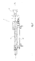
- FIG. 1 shows a machine 1 for marking shaped parts, which are caps 2 of oval shape not shown in Figure 1 for better visibility.
- the marking machine 1 comprises a main frame 3 which supports a marking head 5 provided with a flat punch 51 fixed. A marking tape 53 is provided to be unrolled opposite the punch 51, by means of two coils 55.
- the machine 1 also comprises two mandrels 12 and 14 for supporting the parts 2.
- the upstream mandrel 12 is intended to receive a part 2 , for marking by the marking head 5, while the downstream mandrel 14 is intended to receive a marked part 2, in order to control the quality of its marking.
- the two mandrels 12 and 14 are pivotally mounted on the same support 16 movable relative to the frame 3 parallel to two perpendicular translation axes Y 16 and Z 16 , respectively horizontal and vertical.
- the support 16 is moved relative to the frame 3 by means of an actuator of known type, not shown in the figures.
- Each of the mandrels 12 or 14 has a pivot axis R 12 or R 14 , oriented perpendicularly to the plane defined by the axes Y 16 and Z 16 .
- the upstream mandrel 12 is rotated about the axis R 12 by a drive shaft 121.
- the upstream mandrel 12, associated with the marking head 5 is able to move the part 2 that it supports by relative to the punch 51 fixed for its marking. More specifically, the part 2 is able to roll substantially without sliding under the punch 51 and to move relative to the punch 51 in the direction of the axes Y 16 and Z 16 .
- the tangential velocity of the part 2 to be marked with respect to the punch 51 is substantially constant during marking. She can however be modulated according to the local radius of curvature of the part 2 to be marked.
- the downstream mandrel 14 is rotatably supported by a shaft 141, connected to the drive shaft 121 of the upstream mandrel 12 by a transmission belt 18.
- the rotation of the downstream mandrel 14 about the axis R 14 is slaved to that of the upstream mandrel 12 about the axis R 12 .
- the mandrels 12 and 14 being both supported by and integral in translation of the support 16, the movement of the downstream mandrel 14 is therefore identical to that of the upstream mandrel 12.
- the marking machine 1 comprises three manipulators 4, 6 and 8 fixed on the frame 3 and intended for loading and unloading the mandrels 12 and 14.
- the upstream manipulator 4 is intended to load on the upstream mandrel 12 a part 2 to mark
- the downstream manipulator 8 is intended to discharge the downstream mandrel 14 a marked part 2 whose marking has been controlled.
- the manipulators 4 and 8 are of the type described in FR-A-2,853,274 .
- the intermediate manipulator 6 is intended for the transfer of a part 2, which has been marked on the upstream mandrel 12, towards the downstream mandrel 14, in order to control the quality of its marking.
- This transfer manipulator 6 is known per se. As can be seen in FIG. 2, it comprises a retractable arm 61 slidably mounted relative to the frame 3 and one end of which is provided with a suction cup 63 for gripping the parts 2.
- the manipulator 6 also comprises a jack 65, adapted to slide the arm 61 in its longitudinal direction X 61 which, in the example shown, is substantially horizontal and perpendicular to the plane defined by the axes Y 16 and Z 16 .
- the manipulator 6 transfers each piece 2, once marked, from the upstream mandrel 12 to the downstream mandrel 14. After having grasped a piece 2 marked on the upstream mandrel 12, then removed from this mandrel 12, the manipulator 6 waits for the downstream mandrel 14 to be placed in the axis of this piece 2, by translation of the support 16 relative to 3. When this is the case, the manipulator 6 moves this piece 2 to the downstream mandrel 14 and the loose when it is threaded on the mandrel 14. The manipulator 6 is then placed in the waiting position, at the distance of the trajectories of the mandrels 12 and 14. During its transfer between the mandrels 12 and 14, each part 2 is thus translated along its central axis, in one direction and then in the opposite direction.
- the vertical axis Z 6 represents the position of the manipulator 6.
- the spacing between the upstream manipulator 4 and the transfer manipulator 6, on the one hand, and the spacing between the transfer manipulator 6 and the downstream manipulator 8, on the other hand, are adjustable.
- the spacing between each pair of manipulators is chosen equal to the spacing e between the mandrels 12 and 14.
- the marking machine 1 is also provided with a linear camera 7 intended to control the quality of marking of a marked part 2 carried by the downstream mandrel 14.
- the camera 7 may be of the type marketed by the company DALSA under the reference SPYDER 2 2048 points. It may also be of another type, in particular of the type provided for in FR-A-2,633,062 .
- This camera 7 is supported by a carriage 9 slidably mounted relative to the frame 3 in a direction D 9 parallel to the axis Y 16 .
- the carriage 9 is provided to move the camera 7 so that its reading line coincides permanently, during the control of the quality of the marking of a part 2 carried by the downstream mandrel 14, with the marked surface of this part 2.
- the camera 7 is disposed at a distance corresponding to its focal length f with respect to the external surface 21 of a part 2A carried by the downstream mandrel 14, the part 2A having been previously marked on the upstream mandrel 12 by the punch 51.
- the camera 7 is moved by the carriage 9 parallel to and synchronously with the line L of tangency between the punch 51 and the outer surface 21 of a part 2B being marked on the upstream mandrel 12.
- This line of tangency is perpendicular to the plane of Figure 4 and shown in this figure by a point corresponding to its intersection with the plan of this figure.
- the marking machine 1 makes it possible to control the marking quality of the pieces 2 with a simple movement of the camera 7, this movement being limited to a translation parallel to the Y axis 16 . This is also the case for parts of more complex shape, such as for example polygonal cross section pieces.
- the movement of the camera 7 and the frequency of the shots are defined by an encoder, not shown.
- the recording frequency of the camera 7 is constantly adapted to the running speed of the marked surface 21 of the marked part 2A, this speed being equal to the tangential speed with respect to the punch 51 of the part 2B being marking on the upstream mandrel 12.
- the frequency of shooting increases as the tangential speed of the part 2B relative to the punch 51 increases.
- the support 16 comprises a reinforcing square 161 in the vicinity of the mandrel 14.
- the residual vibrations of the mandrel 14 during of its displacement are recorded and subtracted from the images acquired by the camera 7, in order to obtain corrected images.
- the vibrations of the camera 7 can be taken into account on its carriage 9.
- the marking machine 1 comprises an electronic control and control unit, not shown, which controls its operation.
- this unit controls the manipulators 4, 6 and 8 and the operating means of the mandrel 12, the support 16 and the carriage 9, from information from sensors, also not shown for the sake of clarity.
- a method of marking a shaped part 2B and checking the quality of its marking by means of the marking machine 1 comprises steps as described below, with reference to FIGS. 3 to 7:
- the upstream manipulator 4 and the transfer manipulator 6 respectively place, and substantially simultaneously, a part 2B to be marked on the upstream mandrel 12 and a previously marked part 2A on the downstream mandrel 14.
- the support 16 is then in a first position visible in FIG. 3, in which the upstream mandrel 12 is positioned upstream and below the punch 51, in the vicinity of the upstream end of the punch 51.
- the upstream mandrel 12 is then driven in translation by the support 16 parallel to the axes Y 16 and Z 16 and in rotation about the axis R 12 , so as to move the workpiece 2B with respect to the punch 51 for its marking, as visible in FIG. 4.
- the part 2B is marked by rolling relative to the punch 51, which corresponds to a displacement of the support 16 from its first position, visible in FIG. to a second position, visible in Figure 5. During this marking, the punch 51 bears on the surface 21 of the part 2B along the line of tangency L.
- the part 2A carried by the downstream mandrel 14 and previously marked on the upstream mandrel 12, is displaced by the downstream mandrel 14 relative to the camera 7 for the control of the quality of its marking.
- the movement of the downstream mandrel 14 is slaved to that of the upstream mandrel 12, in translation thanks to the support 16 which simultaneously moves the two mandrels in the plane of the axes Y 16 and Z 16 , and in rotation thanks to the belt 18 which drives the mandrel 14 in rotation about the axis R 14 simultaneously with the rotation of the mandrel 12 about the axis R 12 .
- the control of the quality of the marking of the part 2A takes place by moving the camera 7 parallel to and synchronously with the line of tangency L, thanks to the carriage 9.
- the movements of the support 16 are represented by the double arrows F y and F z in Figure 4, while the corresponding and simultaneous movements of the carriage 9 of the camera 7 are represented by the arrow F ' y .
- the camera 7 is kept at a focal distance f of the marked surface of the part 2A during the inspection, as can be seen in FIG. 4.
- each image acquired by the camera 7 is corrected to take into account any relative vibrations of the downstream mandrel 14 and the camera 7, which ensures the reliability and the accuracy of the control of the quality of the marking of the part 2A carried by the mandrel 14.
- the support 16 When the marking of the part 2B carried by the upstream mandrel 12 and the simultaneous control of the quality of the marking of the part 2A have taken place, the support 16 is in its second position, visible in FIG. this position of the support 16, the transfer manipulator 6 and downstream 8 are able to respectively discharge, and substantially simultaneously, the mandrels 12 and 14. More specifically, the downstream manipulator 8 transfers the part 2A, whose marking has been controlled as being satisfactory by means of the camera 7, the downstream mandrel 14 to a receptacle or evacuation conveyor marked parts, not shown in the figures. Simultaneously, the transfer manipulator 6 grasps the part 2B and removes it from the upstream mandrel 12.
- the support 16 is then brought back from its second position to its first position. In this step, and as shown in FIG. 6, the mandrels 12 and 14 carry no part and the part 2B is carried by the transfer manipulator 6.
- the upstream manipulator 4 and the transfer manipulator 6 respectively place, and substantially simultaneously, a part 2C to be marked on the upstream mandrel 12 and the marked part. 2B on the downstream mandrel 14.
- the control of the quality of the marking of the part 2B then takes place simultaneously with the marking of the part 2C, by repeating the steps of FIGS. 3 to 6, the part 2A being replaced by the part 2B and the room 2B through room 2C.
- the marking machine 1 thus allows both the marking of shaped parts 2 and the quality control of their marking. Movement relative of the camera 7 and the controlled part 2, carried by the downstream mandrel 14, keeps the camera 7 at a focal distance f of the marked surface of the part 2 during the control and thus to ensure a reliable control of the marking. Taking into account the relative vibrations of the mandrel 14 and the camera 7 to correct the images acquired by the camera 7 contributes to the accuracy of the quality control.
- the slaving of the movement of the downstream mandrel 14 to that of the upstream mandrel 12, by means of the support 16 and the belt 18, makes it possible to obtain a machine for marking and quality control of the compact marking, in particular more compact and economical than two machines juxtaposed one of which would be dedicated to the marking and the other to control the quality of the marking.
- the movement of the camera 7 for the control of the marked surface of the parts 2 is effected in a single direction, thanks to the displacement of the part 2 marked by the mandrel 14 both in rotation and in translation in two directions.
- the planar punch 51 may be replaced by a screen printing squeegee associated with a screen printing screen.
- the upstream mandrel 12 moves a piece of shape 2 to be marked under the screen printing screen in a similar manner to the case of the plane punch, the line of tangency between the screen printing doctor and the part 2 to be marked then corresponding to a line of the serigraphy doctor blade oriented parallel to the axis of rotation R 12 of the part 2 to be marked.
- the control of the marking quality of a marked part 2 carried by the downstream mandrel 14, whose movement is slaved to that of the upstream mandrel 12, takes place, as in the case of the plane punch, by moving the camera 7 in parallel.
- the movement of the camera 7 is therefore in this case a translational movement along an axis parallel to the Y axis 16 of FIG. 1.
- the serigraphy squeegee and the camera 7 are displaced by a same carriage in translation in parallel. to the Y axis 16 .
Landscapes
- Engineering & Computer Science (AREA)
- Mechanical Engineering (AREA)
- Quality & Reliability (AREA)
- Printing Methods (AREA)
- Auxiliary Devices For And Details Of Packaging Control (AREA)
- Moulds For Moulding Plastics Or The Like (AREA)
Priority Applications (1)
| Application Number | Priority Date | Filing Date | Title |
|---|---|---|---|
| PL07356021T PL1820647T3 (pl) | 2006-02-21 | 2007-02-20 | Maszyna i sposób znakowania elementów kształtowych |
Applications Claiming Priority (1)
| Application Number | Priority Date | Filing Date | Title |
|---|---|---|---|
| FR0601506A FR2897555B1 (fr) | 2006-02-21 | 2006-02-21 | Machine et procede de marquage de pieces de forme |
Publications (3)
| Publication Number | Publication Date |
|---|---|
| EP1820647A2 true EP1820647A2 (de) | 2007-08-22 |
| EP1820647A3 EP1820647A3 (de) | 2011-03-09 |
| EP1820647B1 EP1820647B1 (de) | 2014-01-15 |
Family
ID=37101858
Family Applications (1)
| Application Number | Title | Priority Date | Filing Date |
|---|---|---|---|
| EP07356021.1A Active EP1820647B1 (de) | 2006-02-21 | 2007-02-20 | Maschine und Verfahren zum Markieren von Formteilen |
Country Status (5)
| Country | Link |
|---|---|
| US (1) | US7823505B2 (de) |
| EP (1) | EP1820647B1 (de) |
| ES (1) | ES2457844T3 (de) |
| FR (1) | FR2897555B1 (de) |
| PL (1) | PL1820647T3 (de) |
Cited By (1)
| Publication number | Priority date | Publication date | Assignee | Title |
|---|---|---|---|---|
| WO2014028619A1 (en) * | 2012-08-14 | 2014-02-20 | Illinois Tool Works Inc. | System and method for applying images to planar and/or non-planar surfaces of a|target object |
Families Citing this family (6)
| Publication number | Priority date | Publication date | Assignee | Title |
|---|---|---|---|---|
| FR2943634B1 (fr) * | 2009-03-24 | 2011-04-22 | Cer | Machine et procede de marquage ou d'etiquetage |
| JP5669535B2 (ja) * | 2010-11-29 | 2015-02-12 | ローランドディー.ジー.株式会社 | 切り抜き加工装置 |
| FR3001649B1 (fr) * | 2013-02-04 | 2015-08-07 | Illinois Tool Works | Machine et procede de marquage d'articles |
| FR3001648B1 (fr) * | 2013-02-04 | 2015-07-17 | Illinois Tool Works | Machine et procede de marquage d'articles |
| JP6486676B2 (ja) * | 2014-12-24 | 2019-03-20 | 株式会社小森コーポレーション | 電子回路の印刷方法および装置 |
| JP6486677B2 (ja) * | 2014-12-24 | 2019-03-20 | 株式会社小森コーポレーション | 電子回路の印刷方法および装置 |
Family Cites Families (8)
| Publication number | Priority date | Publication date | Assignee | Title |
|---|---|---|---|---|
| DE1247904B (de) * | 1961-09-13 | 1967-08-17 | Kurt G Hinterkopf | Selbsttaetige Behandlungsanlage fuer Hohlkoerper, wie Tuben od. dgl. |
| FR2633062B1 (fr) * | 1988-06-21 | 1992-11-27 | Dubuit Mach | Procede pour le controle de qualite d'une impression, et machine d'impression mettant en oeuvre un tel procede |
| US6283022B1 (en) * | 1997-10-17 | 2001-09-04 | Deco Patents, Inc. | Apparatus and method for direct rotary screen printing radiation curable compositions onto cylindrical articles |
| IT1305329B1 (it) * | 1998-10-22 | 2001-05-04 | Omso Spa | Dispositivo automatico di rilevazione della qualita' di stampa suflaconi o bottiglie di forma qualunque |
| US6684770B2 (en) * | 2001-06-29 | 2004-02-03 | Deco Patents, Inc. | Apparatus and method for direct rotary printing compositions onto cylindrical articles |
| US6840166B2 (en) * | 2002-06-12 | 2005-01-11 | Machine Engineering, Inc. | Mandrel trip apparatus |
| FR2860180B1 (fr) * | 2003-09-26 | 2005-12-23 | Dubuit Mach | Machine a imprimer |
| FR2881976B1 (fr) * | 2005-02-15 | 2008-10-03 | Cer Soc Par Actions Simplifiee | Machine et procede de marquage d'un objet |
-
2006
- 2006-02-21 FR FR0601506A patent/FR2897555B1/fr not_active Expired - Lifetime
-
2007
- 2007-02-20 ES ES07356021.1T patent/ES2457844T3/es active Active
- 2007-02-20 US US11/708,063 patent/US7823505B2/en active Active
- 2007-02-20 EP EP07356021.1A patent/EP1820647B1/de active Active
- 2007-02-20 PL PL07356021T patent/PL1820647T3/pl unknown
Cited By (2)
| Publication number | Priority date | Publication date | Assignee | Title |
|---|---|---|---|---|
| WO2014028619A1 (en) * | 2012-08-14 | 2014-02-20 | Illinois Tool Works Inc. | System and method for applying images to planar and/or non-planar surfaces of a|target object |
| US9321256B2 (en) | 2012-08-14 | 2016-04-26 | Illinois Tool Works Inc. | System for applying images to planar surfaces of a target object |
Also Published As
| Publication number | Publication date |
|---|---|
| US7823505B2 (en) | 2010-11-02 |
| US20070199455A1 (en) | 2007-08-30 |
| ES2457844T3 (es) | 2014-04-29 |
| FR2897555B1 (fr) | 2008-04-18 |
| PL1820647T3 (pl) | 2014-07-31 |
| FR2897555A1 (fr) | 2007-08-24 |
| EP1820647A3 (de) | 2011-03-09 |
| EP1820647B1 (de) | 2014-01-15 |
Similar Documents
| Publication | Publication Date | Title |
|---|---|---|
| EP1820647B1 (de) | Maschine und Verfahren zum Markieren von Formteilen | |
| EP1593173B1 (de) | Vorrichtung zur aufwicklung von speichern elektrischer energie | |
| EP2236296B1 (de) | Vorrichtung und Verfahren zum Markieren oder Etikettieren | |
| EP1450986B1 (de) | Bearbeitungsmaschine für langgestreckte profile | |
| EP0853527B1 (de) | Mess-und regelgerät für die bearbeitung von umlaufenden zylindrischen werkstücken | |
| EP0640435A1 (de) | Schleifmaschine | |
| EP0611240B1 (de) | Druckmaschine mit mindestens einem Zylinder mit doppeltem Verfahrweg | |
| WO1997037785A1 (fr) | Machine a cintrer ou a cambrer un profile, et tete de cintrage pour une telle machine | |
| EP0141745B1 (de) | Automatische Maschine zum Biegen in einer räumlichen Konfiguration feiner und gerader Elemente, insbesondere Metalldrähten | |
| CH656082A5 (fr) | Machine pour decoupage par electroerosion avec immobilisation de la chute. | |
| WO2013144477A1 (fr) | Machine de cintrage à tête de pliage mobile autour d'un nez de pliage fixe | |
| FR2685239A1 (fr) | Machine pour l'usinage de pieces a partir de profiles de grande longueur. | |
| EP1775126B1 (de) | Übertragungsvorrichtung von Gegenständen für eine Druckmaschine, Druckmaschine und Übertragungsverfahren | |
| EP0795504A1 (de) | Maschine zum kontinuierlichen Abwickeln von Bobinen mit zumindest einer Einrichtung zum gleichzeitigen Abwickeln von zwei paarweise oder koaxial angeordneten Bobinen | |
| EP1336454B1 (de) | Verfahren und Vorrichtung zur Feinstbearbeitung der Lagerfläche eines Werkstücks, insbesondere für die Feinstbearbeitung der Nockenfläche einer Nockenwelle | |
| WO2003091055A1 (fr) | Dispositif de pose d'un joint d'etancheite sur une carrosserie de vehicule automobile, et procede associe | |
| EP0281488A1 (de) | Drehender Biegekopf für Rohrbiegemaschine | |
| FR2681275A3 (en) | Apparatus for changing a cutting tool built into a machine | |
| FR2881976A1 (fr) | Machine et procede de marquage d'un objet | |
| EP0015850A1 (de) | Transportvorrichtung für kleine Stücke | |
| FR2863934A1 (fr) | Machine d'impression par serigraphie avec dispositif de transfert d'objets a imprimer. | |
| FR2825652A1 (fr) | Machine d'usinage par abrasif de portees d'une piece, notamment de superfinition de manetons de vilebrequins | |
| FR2746682A1 (fr) | Machine a cambrer les fils metalliques | |
| FR2685228A1 (fr) | Machine a cintrer un element du type tige, barre, tube, fil ou analogue. | |
| EP1097757A1 (de) | Verfahren und Vorrichtung zur Qualitätsprüfung der Werkstücksverformungen durch eine Rohrendverformungsvorrichtung |
Legal Events
| Date | Code | Title | Description |
|---|---|---|---|
| PUAI | Public reference made under article 153(3) epc to a published international application that has entered the european phase |
Free format text: ORIGINAL CODE: 0009012 |
|
| AK | Designated contracting states |
Kind code of ref document: A2 Designated state(s): AT BE BG CH CY CZ DE DK EE ES FI FR GB GR HU IE IS IT LI LT LU LV MC NL PL PT RO SE SI SK TR |
|
| AX | Request for extension of the european patent |
Extension state: AL BA HR MK YU |
|
| RAP1 | Party data changed (applicant data changed or rights of an application transferred) |
Owner name: ILLINOIS TOOL WORKS INC. |
|
| PUAL | Search report despatched |
Free format text: ORIGINAL CODE: 0009013 |
|
| AK | Designated contracting states |
Kind code of ref document: A3 Designated state(s): AT BE BG CH CY CZ DE DK EE ES FI FR GB GR HU IE IS IT LI LT LU LV MC NL PL PT RO SE SI SK TR |
|
| AX | Request for extension of the european patent |
Extension state: AL BA HR MK RS |
|
| 17P | Request for examination filed |
Effective date: 20110905 |
|
| AKX | Designation fees paid |
Designated state(s): AT BE BG CH CY CZ DE DK EE ES FI FR GB GR HU IE IS IT LI LT LU LV MC NL PL PT RO SE SI SK TR |
|
| GRAP | Despatch of communication of intention to grant a patent |
Free format text: ORIGINAL CODE: EPIDOSNIGR1 |
|
| INTG | Intention to grant announced |
Effective date: 20130919 |
|
| GRAS | Grant fee paid |
Free format text: ORIGINAL CODE: EPIDOSNIGR3 |
|
| GRAA | (expected) grant |
Free format text: ORIGINAL CODE: 0009210 |
|
| AK | Designated contracting states |
Kind code of ref document: B1 Designated state(s): AT BE BG CH CY CZ DE DK EE ES FI FR GB GR HU IE IS IT LI LT LU LV MC NL PL PT RO SE SI SK TR |
|
| REG | Reference to a national code |
Ref country code: GB Ref legal event code: FG4D Free format text: NOT ENGLISH Ref country code: CH Ref legal event code: EP |
|
| REG | Reference to a national code |
Ref country code: AT Ref legal event code: REF Ref document number: 649626 Country of ref document: AT Kind code of ref document: T Effective date: 20140215 |
|
| REG | Reference to a national code |
Ref country code: IE Ref legal event code: FG4D Free format text: LANGUAGE OF EP DOCUMENT: FRENCH |
|
| REG | Reference to a national code |
Ref country code: DE Ref legal event code: R096 Ref document number: 602007034776 Country of ref document: DE Effective date: 20140227 |
|
| RAP2 | Party data changed (patent owner data changed or rights of a patent transferred) |
Owner name: ILLINOIS TOOL WORKS INC. |
|
| REG | Reference to a national code |
Ref country code: ES Ref legal event code: FG2A Ref document number: 2457844 Country of ref document: ES Kind code of ref document: T3 Effective date: 20140429 |
|
| REG | Reference to a national code |
Ref country code: NL Ref legal event code: VDEP Effective date: 20140115 |
|
| REG | Reference to a national code |
Ref country code: AT Ref legal event code: MK05 Ref document number: 649626 Country of ref document: AT Kind code of ref document: T Effective date: 20140115 |
|
| REG | Reference to a national code |
Ref country code: LT Ref legal event code: MG4D |
|
| PG25 | Lapsed in a contracting state [announced via postgrant information from national office to epo] |
Ref country code: LT Free format text: LAPSE BECAUSE OF FAILURE TO SUBMIT A TRANSLATION OF THE DESCRIPTION OR TO PAY THE FEE WITHIN THE PRESCRIBED TIME-LIMIT Effective date: 20140115 Ref country code: IS Free format text: LAPSE BECAUSE OF FAILURE TO SUBMIT A TRANSLATION OF THE DESCRIPTION OR TO PAY THE FEE WITHIN THE PRESCRIBED TIME-LIMIT Effective date: 20140515 |
|
| REG | Reference to a national code |
Ref country code: PL Ref legal event code: T3 |
|
| PG25 | Lapsed in a contracting state [announced via postgrant information from national office to epo] |
Ref country code: AT Free format text: LAPSE BECAUSE OF FAILURE TO SUBMIT A TRANSLATION OF THE DESCRIPTION OR TO PAY THE FEE WITHIN THE PRESCRIBED TIME-LIMIT Effective date: 20140115 Ref country code: SE Free format text: LAPSE BECAUSE OF FAILURE TO SUBMIT A TRANSLATION OF THE DESCRIPTION OR TO PAY THE FEE WITHIN THE PRESCRIBED TIME-LIMIT Effective date: 20140115 Ref country code: NL Free format text: LAPSE BECAUSE OF FAILURE TO SUBMIT A TRANSLATION OF THE DESCRIPTION OR TO PAY THE FEE WITHIN THE PRESCRIBED TIME-LIMIT Effective date: 20140115 Ref country code: FI Free format text: LAPSE BECAUSE OF FAILURE TO SUBMIT A TRANSLATION OF THE DESCRIPTION OR TO PAY THE FEE WITHIN THE PRESCRIBED TIME-LIMIT Effective date: 20140115 Ref country code: CY Free format text: LAPSE BECAUSE OF FAILURE TO SUBMIT A TRANSLATION OF THE DESCRIPTION OR TO PAY THE FEE WITHIN THE PRESCRIBED TIME-LIMIT Effective date: 20140115 Ref country code: PT Free format text: LAPSE BECAUSE OF FAILURE TO SUBMIT A TRANSLATION OF THE DESCRIPTION OR TO PAY THE FEE WITHIN THE PRESCRIBED TIME-LIMIT Effective date: 20140515 |
|
| BERE | Be: lapsed |
Owner name: ILLINOIS TOOL WORKS INC. Effective date: 20140228 |
|
| PG25 | Lapsed in a contracting state [announced via postgrant information from national office to epo] |
Ref country code: LV Free format text: LAPSE BECAUSE OF FAILURE TO SUBMIT A TRANSLATION OF THE DESCRIPTION OR TO PAY THE FEE WITHIN THE PRESCRIBED TIME-LIMIT Effective date: 20140115 |
|
| REG | Reference to a national code |
Ref country code: CH Ref legal event code: PL |
|
| REG | Reference to a national code |
Ref country code: DE Ref legal event code: R097 Ref document number: 602007034776 Country of ref document: DE |
|
| PG25 | Lapsed in a contracting state [announced via postgrant information from national office to epo] |
Ref country code: RO Free format text: LAPSE BECAUSE OF FAILURE TO SUBMIT A TRANSLATION OF THE DESCRIPTION OR TO PAY THE FEE WITHIN THE PRESCRIBED TIME-LIMIT Effective date: 20140115 Ref country code: DK Free format text: LAPSE BECAUSE OF FAILURE TO SUBMIT A TRANSLATION OF THE DESCRIPTION OR TO PAY THE FEE WITHIN THE PRESCRIBED TIME-LIMIT Effective date: 20140115 Ref country code: CZ Free format text: LAPSE BECAUSE OF FAILURE TO SUBMIT A TRANSLATION OF THE DESCRIPTION OR TO PAY THE FEE WITHIN THE PRESCRIBED TIME-LIMIT Effective date: 20140115 Ref country code: LI Free format text: LAPSE BECAUSE OF NON-PAYMENT OF DUE FEES Effective date: 20140228 Ref country code: CH Free format text: LAPSE BECAUSE OF NON-PAYMENT OF DUE FEES Effective date: 20140228 Ref country code: EE Free format text: LAPSE BECAUSE OF FAILURE TO SUBMIT A TRANSLATION OF THE DESCRIPTION OR TO PAY THE FEE WITHIN THE PRESCRIBED TIME-LIMIT Effective date: 20140115 Ref country code: MC Free format text: LAPSE BECAUSE OF FAILURE TO SUBMIT A TRANSLATION OF THE DESCRIPTION OR TO PAY THE FEE WITHIN THE PRESCRIBED TIME-LIMIT Effective date: 20140115 |
|
| PLBE | No opposition filed within time limit |
Free format text: ORIGINAL CODE: 0009261 |
|
| STAA | Information on the status of an ep patent application or granted ep patent |
Free format text: STATUS: NO OPPOSITION FILED WITHIN TIME LIMIT |
|
| PG25 | Lapsed in a contracting state [announced via postgrant information from national office to epo] |
Ref country code: SK Free format text: LAPSE BECAUSE OF FAILURE TO SUBMIT A TRANSLATION OF THE DESCRIPTION OR TO PAY THE FEE WITHIN THE PRESCRIBED TIME-LIMIT Effective date: 20140115 |
|
| REG | Reference to a national code |
Ref country code: IE Ref legal event code: MM4A |
|
| 26N | No opposition filed |
Effective date: 20141016 |
|
| PG25 | Lapsed in a contracting state [announced via postgrant information from national office to epo] |
Ref country code: IE Free format text: LAPSE BECAUSE OF NON-PAYMENT OF DUE FEES Effective date: 20140220 Ref country code: BE Free format text: LAPSE BECAUSE OF NON-PAYMENT OF DUE FEES Effective date: 20140228 |
|
| REG | Reference to a national code |
Ref country code: DE Ref legal event code: R097 Ref document number: 602007034776 Country of ref document: DE Effective date: 20141016 |
|
| PG25 | Lapsed in a contracting state [announced via postgrant information from national office to epo] |
Ref country code: SI Free format text: LAPSE BECAUSE OF FAILURE TO SUBMIT A TRANSLATION OF THE DESCRIPTION OR TO PAY THE FEE WITHIN THE PRESCRIBED TIME-LIMIT Effective date: 20140115 |
|
| REG | Reference to a national code |
Ref country code: FR Ref legal event code: PLFP Year of fee payment: 10 |
|
| PG25 | Lapsed in a contracting state [announced via postgrant information from national office to epo] |
Ref country code: BG Free format text: LAPSE BECAUSE OF FAILURE TO SUBMIT A TRANSLATION OF THE DESCRIPTION OR TO PAY THE FEE WITHIN THE PRESCRIBED TIME-LIMIT Effective date: 20140115 |
|
| PG25 | Lapsed in a contracting state [announced via postgrant information from national office to epo] |
Ref country code: GR Free format text: LAPSE BECAUSE OF FAILURE TO SUBMIT A TRANSLATION OF THE DESCRIPTION OR TO PAY THE FEE WITHIN THE PRESCRIBED TIME-LIMIT Effective date: 20140416 |
|
| PG25 | Lapsed in a contracting state [announced via postgrant information from national office to epo] |
Ref country code: LU Free format text: LAPSE BECAUSE OF NON-PAYMENT OF DUE FEES Effective date: 20140220 Ref country code: HU Free format text: LAPSE BECAUSE OF FAILURE TO SUBMIT A TRANSLATION OF THE DESCRIPTION OR TO PAY THE FEE WITHIN THE PRESCRIBED TIME-LIMIT; INVALID AB INITIO Effective date: 20070220 |
|
| REG | Reference to a national code |
Ref country code: FR Ref legal event code: PLFP Year of fee payment: 11 |
|
| REG | Reference to a national code |
Ref country code: FR Ref legal event code: PLFP Year of fee payment: 12 |
|
| PGFP | Annual fee paid to national office [announced via postgrant information from national office to epo] |
Ref country code: ES Payment date: 20230301 Year of fee payment: 17 |
|
| PGFP | Annual fee paid to national office [announced via postgrant information from national office to epo] |
Ref country code: TR Payment date: 20230214 Year of fee payment: 17 Ref country code: GB Payment date: 20230227 Year of fee payment: 17 |
|
| P01 | Opt-out of the competence of the unified patent court (upc) registered |
Effective date: 20230606 |
|
| GBPC | Gb: european patent ceased through non-payment of renewal fee |
Effective date: 20240220 |
|
| PG25 | Lapsed in a contracting state [announced via postgrant information from national office to epo] |
Ref country code: GB Free format text: LAPSE BECAUSE OF NON-PAYMENT OF DUE FEES Effective date: 20240220 |
|
| PG25 | Lapsed in a contracting state [announced via postgrant information from national office to epo] |
Ref country code: GB Free format text: LAPSE BECAUSE OF NON-PAYMENT OF DUE FEES Effective date: 20240220 |
|
| REG | Reference to a national code |
Ref country code: ES Ref legal event code: FD2A Effective date: 20250331 |
|
| PG25 | Lapsed in a contracting state [announced via postgrant information from national office to epo] |
Ref country code: ES Free format text: LAPSE BECAUSE OF NON-PAYMENT OF DUE FEES Effective date: 20240221 |
|
| PGFP | Annual fee paid to national office [announced via postgrant information from national office to epo] |
Ref country code: PL Payment date: 20250203 Year of fee payment: 19 |
|
| PGFP | Annual fee paid to national office [announced via postgrant information from national office to epo] |
Ref country code: DE Payment date: 20260227 Year of fee payment: 20 |
|
| PGFP | Annual fee paid to national office [announced via postgrant information from national office to epo] |
Ref country code: IT Payment date: 20260219 Year of fee payment: 20 |
|
| PGFP | Annual fee paid to national office [announced via postgrant information from national office to epo] |
Ref country code: FR Payment date: 20260225 Year of fee payment: 20 |