EP1820671A2 - System zur Erkennung von Reifendaten - Google Patents
System zur Erkennung von Reifendaten Download PDFInfo
- Publication number
- EP1820671A2 EP1820671A2 EP07002618A EP07002618A EP1820671A2 EP 1820671 A2 EP1820671 A2 EP 1820671A2 EP 07002618 A EP07002618 A EP 07002618A EP 07002618 A EP07002618 A EP 07002618A EP 1820671 A2 EP1820671 A2 EP 1820671A2
- Authority
- EP
- European Patent Office
- Prior art keywords
- resonator
- crystal
- pressure
- frequency
- measured value
- Prior art date
- Legal status (The legal status is an assumption and is not a legal conclusion. Google has not performed a legal analysis and makes no representation as to the accuracy of the status listed.)
- Withdrawn
Links
- 239000013078 crystal Substances 0.000 claims abstract description 121
- 230000010355 oscillation Effects 0.000 description 21
- 238000000034 method Methods 0.000 description 17
- 230000000694 effects Effects 0.000 description 12
- 238000004519 manufacturing process Methods 0.000 description 12
- 238000005259 measurement Methods 0.000 description 12
- 238000005520 cutting process Methods 0.000 description 7
- 238000009530 blood pressure measurement Methods 0.000 description 6
- 230000006866 deterioration Effects 0.000 description 6
- 230000005540 biological transmission Effects 0.000 description 5
- 239000003990 capacitor Substances 0.000 description 5
- 238000010586 diagram Methods 0.000 description 4
- 238000000151 deposition Methods 0.000 description 3
- 238000001514 detection method Methods 0.000 description 3
- 239000000463 material Substances 0.000 description 3
- 238000012545 processing Methods 0.000 description 3
- 239000000853 adhesive Substances 0.000 description 2
- 230000001070 adhesive effect Effects 0.000 description 2
- 238000004140 cleaning Methods 0.000 description 2
- 230000008878 coupling Effects 0.000 description 2
- 238000010168 coupling process Methods 0.000 description 2
- 238000005859 coupling reaction Methods 0.000 description 2
- 230000008021 deposition Effects 0.000 description 2
- 238000005530 etching Methods 0.000 description 2
- 230000035882 stress Effects 0.000 description 2
- 238000012360 testing method Methods 0.000 description 2
- RIUWBIIVUYSTCN-UHFFFAOYSA-N trilithium borate Chemical compound [Li+].[Li+].[Li+].[O-]B([O-])[O-] RIUWBIIVUYSTCN-UHFFFAOYSA-N 0.000 description 2
- WSMQKESQZFQMFW-UHFFFAOYSA-N 5-methyl-pyrazole-3-carboxylic acid Chemical compound CC1=CC(C(O)=O)=NN1 WSMQKESQZFQMFW-UHFFFAOYSA-N 0.000 description 1
- 229910003334 KNbO3 Inorganic materials 0.000 description 1
- 229910003327 LiNbO3 Inorganic materials 0.000 description 1
- 229910012463 LiTaO3 Inorganic materials 0.000 description 1
- 230000032683 aging Effects 0.000 description 1
- 238000012937 correction Methods 0.000 description 1
- 230000002596 correlated effect Effects 0.000 description 1
- 230000000875 corresponding effect Effects 0.000 description 1
- 230000007613 environmental effect Effects 0.000 description 1
- 230000005284 excitation Effects 0.000 description 1
- 239000000284 extract Substances 0.000 description 1
- 238000009413 insulation Methods 0.000 description 1
- JQJCSZOEVBFDKO-UHFFFAOYSA-N lead zinc Chemical compound [Zn].[Pb] JQJCSZOEVBFDKO-UHFFFAOYSA-N 0.000 description 1
- GQYHUHYESMUTHG-UHFFFAOYSA-N lithium niobate Chemical compound [Li+].[O-][Nb](=O)=O GQYHUHYESMUTHG-UHFFFAOYSA-N 0.000 description 1
- 238000012986 modification Methods 0.000 description 1
- 230000004048 modification Effects 0.000 description 1
- 238000005498 polishing Methods 0.000 description 1
- 238000007517 polishing process Methods 0.000 description 1
- UKDIAJWKFXFVFG-UHFFFAOYSA-N potassium;oxido(dioxo)niobium Chemical compound [K+].[O-][Nb](=O)=O UKDIAJWKFXFVFG-UHFFFAOYSA-N 0.000 description 1
- 238000007789 sealing Methods 0.000 description 1
- 239000006104 solid solution Substances 0.000 description 1
Images


Classifications
-
- B—PERFORMING OPERATIONS; TRANSPORTING
- B60—VEHICLES IN GENERAL
- B60C—VEHICLE TYRES; TYRE INFLATION; TYRE CHANGING; CONNECTING VALVES TO INFLATABLE ELASTIC BODIES IN GENERAL; DEVICES OR ARRANGEMENTS RELATED TO TYRES
- B60C23/00—Devices for measuring, signalling, controlling, or distributing tyre pressure or temperature, specially adapted for mounting on vehicles; Arrangement of tyre inflating devices on vehicles, e.g. of pumps or of tanks; Tyre cooling arrangements
- B60C23/02—Signalling devices actuated by tyre pressure
- B60C23/04—Signalling devices actuated by tyre pressure mounted on the wheel or tyre
- B60C23/0408—Signalling devices actuated by tyre pressure mounted on the wheel or tyre transmitting the signals by non-mechanical means from the wheel or tyre to a vehicle body mounted receiver
- B60C23/0422—Signalling devices actuated by tyre pressure mounted on the wheel or tyre transmitting the signals by non-mechanical means from the wheel or tyre to a vehicle body mounted receiver characterised by the type of signal transmission means
- B60C23/0433—Radio signals
- B60C23/0447—Wheel or tyre mounted circuits
- B60C23/0449—Passive transducers, e.g. using surface acoustic waves, backscatter technology or pressure sensitive resonators
-
- B—PERFORMING OPERATIONS; TRANSPORTING
- B60—VEHICLES IN GENERAL
- B60C—VEHICLE TYRES; TYRE INFLATION; TYRE CHANGING; CONNECTING VALVES TO INFLATABLE ELASTIC BODIES IN GENERAL; DEVICES OR ARRANGEMENTS RELATED TO TYRES
- B60C23/00—Devices for measuring, signalling, controlling, or distributing tyre pressure or temperature, specially adapted for mounting on vehicles; Arrangement of tyre inflating devices on vehicles, e.g. of pumps or of tanks; Tyre cooling arrangements
- B60C23/02—Signalling devices actuated by tyre pressure
- B60C23/04—Signalling devices actuated by tyre pressure mounted on the wheel or tyre
- B60C23/0408—Signalling devices actuated by tyre pressure mounted on the wheel or tyre transmitting the signals by non-mechanical means from the wheel or tyre to a vehicle body mounted receiver
- B60C23/0422—Signalling devices actuated by tyre pressure mounted on the wheel or tyre transmitting the signals by non-mechanical means from the wheel or tyre to a vehicle body mounted receiver characterised by the type of signal transmission means
- B60C23/0433—Radio signals
Definitions
- the present invention relates to systems of detecting tire information and, more particularly, to a system of detecting tire information including a pressure concerning a tire used for an automobile or the like.
- radio transmission systems have been proposed, in which measured values, such as pressures, of tires used for automobiles or the likes are transmitted by radio waves to controllers provided in the bodies of the automobiles and the transmitted measured values are evaluated to, for example, send out warning messages for the drivers (for example, refer to US Patent No.6,378,360 ).
- a controller shown in Fig. 2 is provided in the body of the vehicle and a measured value transmitter (transponder) shown in Fig. 3 is provided in a tire of the vehicle.
- the controller includes a carrier wave oscillator G1, a modulator MO1, and an oscillator G2.
- the carrier wave oscillator G1 generates a carrier wave having a frequency f1 of about 2.4 GHz and supplies the generated carrier wave to the modulator MO1.
- the oscillator G2 outputs an oscillation signal for modulation.
- the oscillator G2 supplies the oscillation signal having a frequency f2 close to the resonant frequency of a resonator in the transponder, described below, to the modulator MO1.
- the carrier wave supplied from the carrier wave oscillator G1 is amplitude-modulated in accordance with the oscillation signal supplied from the oscillator G2.
- the amplitude-modulated high-frequency signal of 2.4 GHz is amplified by an amplifier (not shown) and the amplified high-frequency signal is emitted from an antenna A1 near the tire.
- the controller also includes a switch S1, a receiver E1, and a timer T1.
- the switch S1 is used to switch the availability of the amplitude modulation in the modulator MO1.
- the receiver E1 receives a high-frequency signal emitted from the transponder to calculate a measured value V1, such as a pressure in the tire.
- the timer T1 controls the switching timing in the switch S1 and the state of the receiver E1. After the availability of the amplitude modulation of the carrier wave is switched in accordance with the switching timing controlled by the timer T1 and the amplitude-modulated high-frequency signal is transmitted for a predetermined time period, the amplitude modulation is stopped at a time t1 and the non-modulated carrier wave is transmitted since the time t1.
- the receiver E1 is enabled at a time t2 about one millisecond or less after the time t1 to receive the high-frequency signal supplied from the transponder through an antenna A4.
- the transponder includes a low-pass filter L11/C11, a varactor diode (hereinafter simply referred to as a "diode”) D11, a capacitive pressure sensor (hereinafter simply referred to as a “pressure sensor”) SC11, and a resonator including a crystal oscillator Q11.
- the diode D11 functions as a modulator-demodulator.
- the capacitance of the pressure sensor SC11 is varied with the pressure in the tire.
- the crystal oscillator Q11 is excited by a frequency component included in the high-frequency signal supplied from the controller.
- the carrier wave of 2.4 GHz is removed from the high-frequency signal supplied from the controller by the low-pass filter L11/C11, and the high-frequency signal is demodulated by the diode D11.
- a signal having a frequency equal to that of the oscillation signal supplied from the oscillator G2 is extracted. Since the resonant frequency of the resonator is close to the frequency of the oscillation signal supplied from the oscillator G2, the resonator is excited by the extracted signal. This excitation generates a signal having the resonant frequency of the resonator. Since the resonant frequency of the resonator is varied with a variation in the capacitance of the pressure sensor SC11 caused by the pressure in the tire, the generated signal having the resonant frequency is also affected by the pressure in the tire.
- the controller stops the amplitude modulation and transmits the non-modulated carrier wave.
- the resonator in the transponder continues to oscillate for about one millisecond or more even after the amplitude modulation is stopped.
- the non-modulated carrier wave supplied from the controller is amplitude-modulated by the diode D11 in accordance with the signal having the resonant frequency of the resonator and the amplitude-modulated signal is emitted from an antenna A3.
- the receiver E1 in the controller receives the amplitude-modulated high-frequency signal through the antenna A4 and extracts the signal having the resonant frequency through a demodulator (not shown) to calculate the measured value V1, such as the pressure in the tire.
- the transponder may further include a resonator including a reference crystal oscillator or may be provided with another resonator to transmit a measured value, such as a temperature or a structural stress of the tire, and the controller may calculate the measured value.
- the resonant frequency of the resonator included in the transponder in the radio transmission system described above is not only affected by the tire information whose measured value is to be yielded, such as the pressure in the tire, but also varied with factors, such as the temperature in the tire. Consequently, there is a problem in that a variation in the temperature in the tire can cause an error of the measured value to inhibit accurate detection of the measured value.
- the transponder further includes the reference resonator and the measured value, such as the pressure in the tire, is calculated, the temperature characteristics and the deterioration characteristics with age are varied between the resonators. Also in this case, there is a problem in that an error of the measured value can be caused to inhibit accurate detection of the measured value.
- a system of detecting tire information includes a measured value transmitter that includes a first resonator with a pressure sensor and a second resonator without the pressure sensor and that is mounted in a tire of a vehicle and a controller that is provided in the body of the vehicle and that transmits a signal used for resonance of the first and second resonators to the measured value transmitter and receives from the measured value transmitter a signal associated with the resonant frequency of the first resonator and a signal associated with the resonant frequency of the second resonator to calculate a measured value on the basis of the resonant frequencies of the first and second resonators, extracted from both of the signals.
- characteristics of a piezoelectric single-crystal oscillator included in the first resonator are made closely analogous to those of a piezoelectric single-crystal oscillator included in the second resonator.
- the resonant frequencies of both of the resonators are similarly affected by any variation in the temperature in the tire or any deterioration with age of the piezoelectric single-crystal oscillators.
- the calculation of the measured value in accordance with the resonant frequencies of the first and second resonators allows the effect of factors including the temperature in the tire to be reduced to accurately detect the measured value, such as the pressure in the tire.
- the piezoelectric single-crystal oscillators included in the first and second resonators be crystal oscillators.
- the crystal oscillators have a higher Q factor and the return frequency is rather constant, so that it is possible to realize stable measurement, compared with a case where other piezoelectric single-crystal oscillators are used.
- crystal blanks used as the crystal oscillators included in the first and second resonators be manufactured from a single wafer. Manufacturing the crystal blanks used as the crystal oscillators from a single wafer allows the characteristics of the crystal oscillator used in the first resonator to be made closely analogous to those of the crystal oscillator used in the second resonator.
- adjacent crystal blanks on a single wafer be used as the crystal oscillators included in the first and second resonators.
- the use of adjacent crystal blanks on a single wafer as the crystal oscillators included in the first and second resonators allows the characteristics of the crystal oscillator used in the first resonator to be made more closely analogous to those of the crystal oscillator used in the second resonator.
- the characteristics of the crystal oscillators included in the first and second resonators include at least temperature characteristics.
- the temperature characteristics of the first resonator is made closely analogous to those of the second resonator, any effect of a variation in the temperature in the tire can be detected with a smaller error, thus allowing accurate detection of the measured value, such as the pressure in the tire.
- the present invention it is possible to reduce any effect of information other than the tire information to be measured (for example, any effect of factors including the temperature in the tire) to accurately detect the tire information to be measured, such as the pressure in the tire.
- a system of detecting tire information for a vehicle includes a controller provided in the body of the vehicle and a measured value transmitter (hereinafter referred to as a "transponder") mounted in a tire of the vehicle, as in the system of detecting tire information (radio transmission system) described in "Description of the Related Art".
- a transponder mounted in a tire of the vehicle, as in the system of detecting tire information (radio transmission system) described in "Description of the Related Art”.
- the system of detecting tire information detects a pressure in the tire in the following description, the system may detect, for example, a structural stress of the tire.
- the system of detecting tire information according to the embodiment of the present invention differs from the system of detecting tire information in the related art in the configuration of the transponder.
- the configuration of the controller will be described only in terms of components that are different from those shown in Fig. 2.
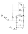
- Fig. 1 is a diagram schematically showing an example of the circuit configuration of the transponder in the system of detecting tire information according to the embodiment of the present invention.
- the transponder according to the embodiment of the present invention differs from transponders in the related art in inclusion of two resonators.
- One resonator includes a crystal oscillator Q1 for measuring a pressure, as in the transponder in the related art, and the other resonator includes a crystal oscillator Q2 for reference, which the transponder in the related art does not include.
- the former resonator is hereinafter called a pressure resonator 1 and the latter resonator is hereinafter called a reference resonator 2 for convenience.
- the pressure resonator 1 functions as a first resonator and the reference resonator 2 functions as a second resonator.
- the crystal oscillator described above is a representative example of a piezoelectric single-crystal oscillator. A case where the crystal oscillator is used as the piezoelectric single-crystal oscillator will be described in the following description.
- the pressure resonator 1 includes the crystal oscillator Q1, a capacitor (not shown), and a capacitive pressure sensor (hereinafter referred to as a "pressure sensor") SC1.
- the capacitor and the pressure sensor SC1 are connected to the crystal oscillator Q1.
- the pressure resonator 1 has a resonant frequency of, for example, 9.803 MHz.
- the resonant frequency of the pressure resonator 1 is varied with the pressure in the tire detected by the pressure sensor SC1.
- the reference resonator 2 includes the crystal oscillator Q2 and a capacitor (not shown) connected the crystal oscillator Q2.
- the reference resonator 2 has a resonant frequency of, for example, 9.800 MHz.
- the pressure resonator 1 is connected to an antenna A3 via a coupling capacitor C21 and the reference resonator 2 is connected to the antenna A3 via a coupling capacitor C22, so that the pressure resonator 1 and the reference resonator 2 are affected by each other only in a level that causes no problem of the measurement. Accordingly, the resonant frequency of the reference resonator 2 is not affected by the pressure detected by the pressure sensor SC1.
- the resonant frequency of the pressure resonator 1 is affected by a variation in the environment in the tire, for example, a variation in the temperature in the tire, in addition to the capacitance of the pressure sensor SC1, which is varied with the pressure in the tire whose measured value is to be yielded.
- the reference resonator 2 that does not include the pressure sensor SC1 and the measurement of the resonant frequency of the reference resonator 2 allow only the effect of a variation in the environment to be measured. Consequently, the pressure in the tire from which the effect of a variation in the environment is removed and which is detected by the pressure sensor SC1 can be measured from the resonant frequencies of the two resonators.
- a low-pass filter L1/C1 functions similarly to the low-pass filter L11/C11 and a varactor diode D1 (hereinafter referred to as a "diode") D1 functions similarly to the diode D11.
- the oscillator G2 generates an oscillation signal having a frequency f2 close to the resonant frequency of the reference resonator 2 and an oscillation signal having a frequency f3 close to the resonant frequency of the pressure resonator 1.
- the oscillation signal having a center frequency of 9.800 MHz and the oscillation signal having a center frequency of 9.803 MHz are generated, and the carrier wave having the frequency f1 is amplitude-modulated in accordance with the generated oscillation signals.
- the availability of the amplitude modulation is switched by the switch S1, as in the controller in the
- the amplitude modulation is stopped. Then, after the carrier wave having the frequency f1 is amplitude-modulated in accordance with the oscillation signal having the frequency f3 (the oscillation signal having a center frequency of 9.803 MHz), the amplitude modulation is stopped.
- the reference resonator 2 continues to oscillate for about one millisecond, as in the transponder in the related art, even after the amplitude modulation in accordance with the former oscillation signal having the frequency f2 is stopped, the non-modulated carrier wave having the frequency f1 is amplitude-modulated by the diode D1 in accordance with a signal having the resonant frequency of the reference resonator 2 and the amplitude-modulated signal is emitted from the antenna A3.
- the pressure resonator 1 continues to oscillate for about one millisecond even after the amplitude modulation in accordance with the latter oscillation signal having the frequency f3 is stopped, the non-modulated carrier wave having the frequency f1 is amplitude-modulated by the diode D1 in accordance with a signal having the resonant frequency of the pressure resonator 1 and the amplitude-modulated signal is emitted from the antenna A3.
- the resonant frequencies of the reference resonator 2 and the pressure resonator 1 are similarly affected by factors, such as the temperature in the tire.
- the resonant frequency of the pressure resonator 1 is also affected by a variation in the pressure detected by the pressure sensor SC1.
- the resonant frequency of the reference resonator 2 is not affected by a variation in the pressure detected by the pressure sensor SC1.
- the controller receives the high-frequency signal amplitude-modulated in accordance with signal having the resonant frequency of the reference resonator 2 and the high-frequency signal amplitude-modulated in accordance with the signal having the resonant frequency of the pressure resonator 1, which resonant frequencies are affected by a variation in the pressure in the above manner.
- the controller determines a difference in the frequency between the resonant frequency extracted from the former high-frequency signal (hereinafter referred to as a "reference measurement frequency” as needed) and the resonant frequency extracted from the latter high-frequency signal (hereinafter referred to as a "pressure measurement frequency" as needed) to calculate a pressure in the tire.
- a correlation table is created by using the reference measurement frequencies, the pressure measurement frequencies, and the pressures in the tire to determine a pressure in the tire from the correlation table.
- a temperature may be measured from the reference measurement frequency to calculate a pressure on the basis of the correlated data concerning the pressure measurement frequency for every temperature and the measured value of the pressure measurement frequency.
- the pressure in the tire is directly or indirectly calculated from the reference measurement frequency and the pressure measurement frequency.
- the amplitude modulation of the carrier wave having the frequency f1 in accordance with the oscillation signal having a frequency of 9.800 MHz is shifted in time from the amplitude modulation of the carrier wave having the frequency f1 in accordance with the oscillation signal having a frequency of 9.803 MHz in the controller in the above description.
- the time when the amplitude modulation is performed may be appropriately changed.
- the amplitude modulation of the carrier wave having the frequency f1 in accordance with the oscillation signal having a frequency of 9.800 MHz may be performed simultaneously with the amplitude modulation of the carrier wave having the frequency f1 in accordance with the oscillation signal having a frequency of 9.803 MHz.
- the self resonant frequency of the crystal oscillator Q1 included in the pressure resonator 1 is set so as to roughly coincide with that of the crystal oscillator Q2 included in the reference resonator 2.
- the self resonant frequencies are not limited to the above setting.
- the self resonant frequency of the crystal oscillator Q1 included in the pressure resonator 1 need not roughly coincide with that of the crystal oscillator Q2 included in the reference resonator 2, as long as the resonant frequencies of the pressure resonator 1 and the reference resonator 2 can be set to the above values.
- the characteristics of the crystal oscillator included in the pressure resonator 1 are set so as to be closely analogous to those of the crystal oscillator included in the reference resonator 2.
- the characteristics include the resonant frequency characteristics when the environment is varied and the resonant frequency characteristics involved in the deterioration effects of time on materials and the deterioration in the structure of the resonators. Since the pressure resonator 1 and the reference resonator 2 are provided in the same tire, the pressure resonator 1 and the reference resonator 2 are similarly affected by a variation in the environment in the tire, for example, a variation in the temperature in the tire.
- the environmental characteristics for example, the temperature characteristics of the two crystal oscillators used in the two resonators are different from each other even when the pressure resonator 1 and the reference resonator 2 are similarly affected by a variation in the environment in the tire, the resonant frequency of the pressure resonator 1 is not varied similarly to that of the reference resonator 2 under the effect of the variation in the environment in the tire.
- any error can be caused in the calculation of the pressure.
- the temperature characteristics are particularly important among the characteristics because the crystal oscillators are generally sensitive to the temperature and the temperature in the tire is significantly varied.
- the main reason for the provision of the reference resonator 2 is to correct any effect of the temperature on the pressure resonator 1. Since an error can be caused in the correction if the crystal oscillator in the pressure resonator 1 has temperature characteristics different from those of the crystal oscillator in the reference resonator 2, the temperature characteristics become important. In addition, it is necessary to take measures against the deterioration effects of time on materials in view of any aging error.
- the crystal oscillator Q1 is manufactured in approximately the same manufacturing conditions as those of the crystal oscillator Q2 in the transponder according to the embodiment of the present invention. Normal manufacturing processes of the crystal oscillator will now be roughly described. Conditions for manufacturing the crystal oscillator used in the transponder according to the embodiment of the present invention will also be described.
- the manufacturing processes of the crystal oscillator normally include a surface grinding process (Lambert process) for defining the X, Y, and Z axes of an artificial crystal; a wafer cutting process of mechanically cutting the artificial crystal after the Lambert process at a predetermined angle into a wafer-like shape; a first slicing and outlining process of slicing and processing the artificial crystal after the wafer cutting process to produce a wafer; a polishing process for adjusting the thickness of the wafer, which determines the frequency of a crystal blank; a second slicing and outlining process of processing the crystal blank into a specified shape of designed values; a beveling process of cutting the edges in order to centralize the oscillation in the central part of the crystal blank; an etching and cleaning process of chemically removing the processed layer resulting from the polishing and improving the frequency accuracy; a deposition and assembly process of depositing electrodes on the crystal blank and fixing the crystal blank having the electrodes deposited thereon in a retainer with conductive adhesive; a
- the crystal blank having a size corresponding to the two crystal blanks finally used as the crystal oscillators is produced.
- the two electrodes are deposited on the crystal blank in the deposition and assembly process.
- the crystal blank is divided into two in a third cutting and outlining process and the crystal blanks resulting from the division are fixed in the retainer with the conductive adhesive. Since the crystal blanks used as the two crystal oscillators are arranged side by side and manufactured in the same manufacturing processes until the third cutting and outlining process, it is possible to make the characteristics of the crystal oscillators closely analogue to each other.
- the crystal blanks may be fixed in different retainers or in the same retainer.
- the crystal blanks used as the crystal oscillators Q1 and Q2 are manufactured from one crystal blank on a single wafer in the above example.
- the respective crystal oscillators may be manufactured from adjacent two crystal blanks on a single wafer, instead of manufacturing the two crystal oscillators from one crystal blank, and the crystal oscillators may be used as the crystal oscillator Q1 in the pressure resonator 1 and the crystal oscillator Q2 in the reference resonator 2.
- the two crystal oscillators manufactured from different crystal blanks which place parts on a single wafer may also be used, although the performance can be degraded in some degree.
- the piezoelectric single-crystal oscillators are not limited to the oscillators made of crystal.
- oscillators resulting from processing of piezoelectric single crystals of lithium tantalate (LiTaO 3 ), lithium niobate (LiNbO 3 ), lithium borate (Li 2 B 4 O 7 ), potassium niobate (KNbO 3 ), langasite (La 3 Ga 5 SiO 14 ), or langanite (La 3 Nb 0.5 Ga 5.5 O14) or solid solution single crystals of zinc lead niobate-lead titanate may be used in the pressure resonator 1 and the reference resonator 2.
- the crystal oscillators Since multiple oscillators are manufactured from the wafer, as in the crystal oscillators, two oscillators having analogous characteristics can be yielded in the manufacturing process and can be used as the piezoelectric single-crystal oscillators according to the embodiment of the present invention.
- a method that is similar to that of the crystal oscillators but is varied depending on the used material can be adopted. Since the crystal oscillators have a Q factor higher than the Q factors of other piezoelectric single-crystal oscillators, the return frequency is rather constant and, therefore, the stable measurement can realized. Consequently, the crystal oscillators are most suitable for providing the system of detecting tire information having a higher measurement accuracy.
- the transponder includes the pressure resonator 1 with the pressure sensor and the reference resonator 2 without the pressure sensor, and the controller transmits the signal used for the resonance of the reference resonator 2 and the pressure resonator 1 and receives the signals modulated in accordance with the resonant frequencies of the two resonators from the transponder to calculate a measured value on the basis of the difference in the frequency between the resonant frequencies of the reference resonator 2 and the pressure resonator 1, extracted from the signals.
- the characteristics of the crystal oscillator Q1 in the pressure resonator 1 are made closely analogous to those of the crystal oscillator Q2 in the reference resonator 2.
- the resonant frequencies of both of the resonators are similarly affected by any variation in the temperature in the tire or any deterioration with age of the crystal oscillators.
- the calculation of the measured value in accordance with the resonant frequencies of the pressure resonator 1 and the reference resonator 2 allows the effect of factors including the temperature in the tire to be removed, so that the measured value, such as the pressure in the tire, can be accurately detected.
- the crystal blanks used as the crystal oscillator Q1 in the pressure resonator 1 and the crystal oscillator Q2 in the reference resonator 2 are manufactured from a single wafer or a single crystal blank in the system of detecting tire information according to the embodiment of the present invention.
- the manufacture of the crystal blanks in this manner can make the characteristics of the crystal oscillator in the pressure resonator 1 closely analogous to those of the crystal oscillator in the reference resonator 2.
Landscapes
- Engineering & Computer Science (AREA)
- Mechanical Engineering (AREA)
- Measuring Fluid Pressure (AREA)
- Arrangements For Transmission Of Measured Signals (AREA)
Applications Claiming Priority (1)
| Application Number | Priority Date | Filing Date | Title |
|---|---|---|---|
| JP2006040497A JP2007216857A (ja) | 2006-02-17 | 2006-02-17 | タイヤ情報検出装置 |
Publications (1)
| Publication Number | Publication Date |
|---|---|
| EP1820671A2 true EP1820671A2 (de) | 2007-08-22 |
Family
ID=38016971
Family Applications (1)
| Application Number | Title | Priority Date | Filing Date |
|---|---|---|---|
| EP07002618A Withdrawn EP1820671A2 (de) | 2006-02-17 | 2007-02-07 | System zur Erkennung von Reifendaten |
Country Status (3)
| Country | Link |
|---|---|
| US (1) | US20070200644A1 (de) |
| EP (1) | EP1820671A2 (de) |
| JP (1) | JP2007216857A (de) |
Cited By (3)
| Publication number | Priority date | Publication date | Assignee | Title |
|---|---|---|---|---|
| EP1839911A3 (de) * | 2006-03-31 | 2011-09-21 | Alps Electric Co., Ltd. | Reifeninformationsdetektionssystem |
| GB2499181B (en) * | 2011-12-20 | 2016-01-20 | Silent Sensors Ltd | Measurement sensor |
| CN111483276A (zh) * | 2020-05-13 | 2020-08-04 | 郑州跃博汽车电器有限公司 | 提高胎压监测器稳定性的方法及应用该方法的胎压监测器 |
Families Citing this family (4)
| Publication number | Priority date | Publication date | Assignee | Title |
|---|---|---|---|---|
| JP4790527B2 (ja) * | 2006-07-21 | 2011-10-12 | アルプス電気株式会社 | タイヤ情報検出装置 |
| JP5085478B2 (ja) * | 2008-09-18 | 2012-11-28 | アルプス電気株式会社 | トランスポンダ |
| FI126136B (en) * | 2014-09-03 | 2016-07-15 | Metso Flow Control Oy | Integrated passive RFID transponder chip and passive RFID sensor tag |
| CN110217057A (zh) * | 2019-07-04 | 2019-09-10 | 北京首汽智行科技有限公司 | 用于共享汽车的胎压监测装置与系统及方法 |
Family Cites Families (5)
| Publication number | Priority date | Publication date | Assignee | Title |
|---|---|---|---|---|
| AU2002345967A1 (en) * | 2001-06-25 | 2003-01-08 | 3Dm Technologies, Inc. | Tire sensor |
| JP2006076432A (ja) * | 2004-09-09 | 2006-03-23 | Alps Electric Co Ltd | タイヤ情報検出装置 |
| JP2006131196A (ja) * | 2004-11-09 | 2006-05-25 | Alps Electric Co Ltd | タイヤ情報検出装置 |
| JP2006142856A (ja) * | 2004-11-16 | 2006-06-08 | Alps Electric Co Ltd | タイヤ情報検出装置 |
| JP4934341B2 (ja) * | 2006-03-31 | 2012-05-16 | アルプス電気株式会社 | タイヤ情報検出装置 |
-
2006
- 2006-02-17 JP JP2006040497A patent/JP2007216857A/ja not_active Withdrawn
-
2007
- 2007-02-07 EP EP07002618A patent/EP1820671A2/de not_active Withdrawn
- 2007-02-16 US US11/676,028 patent/US20070200644A1/en not_active Abandoned
Cited By (3)
| Publication number | Priority date | Publication date | Assignee | Title |
|---|---|---|---|---|
| EP1839911A3 (de) * | 2006-03-31 | 2011-09-21 | Alps Electric Co., Ltd. | Reifeninformationsdetektionssystem |
| GB2499181B (en) * | 2011-12-20 | 2016-01-20 | Silent Sensors Ltd | Measurement sensor |
| CN111483276A (zh) * | 2020-05-13 | 2020-08-04 | 郑州跃博汽车电器有限公司 | 提高胎压监测器稳定性的方法及应用该方法的胎压监测器 |
Also Published As
| Publication number | Publication date |
|---|---|
| JP2007216857A (ja) | 2007-08-30 |
| US20070200644A1 (en) | 2007-08-30 |
Similar Documents
| Publication | Publication Date | Title |
|---|---|---|
| EP1820671A2 (de) | System zur Erkennung von Reifendaten | |
| US20070194897A1 (en) | System of detecting tire information | |
| EP1839911B1 (de) | Reifeninformationsdetektionssystem | |
| CN107852144B (zh) | 弹性波谐振器、弹性波滤波器、分波器、通信装置以及弹性波谐振器的设计方法 | |
| US20190165763A1 (en) | Elastic wave device, high-frequency front-end circuit, and communication apparatus | |
| US20070107519A1 (en) | Wireless acoustic wave sensor system for use in vehicle applications | |
| US20070040473A1 (en) | Hybrid resonant structure | |
| US20090217760A1 (en) | Sensing apparatus | |
| KR20200140281A (ko) | 알에프아이디(rfid) 및 센서 애플리케이션을 위한 표면 탄성파 태그용 복합 기판 | |
| KR102591286B1 (ko) | 전극 정의 공진기 | |
| US11121696B2 (en) | Electrode defined resonator | |
| JP2011028424A (ja) | センサ機能付きrfidタグ、およびそのrfidタグを用いたrfidシステム | |
| US7916012B2 (en) | Hybrid resonant structure to verify parameters of a tire | |
| JP2003534561A (ja) | 測定量を遠隔検出するためのセンサ、センサシステムおよび方法 | |
| US20060001329A1 (en) | FBAR device frequency stabilized against temperature drift | |
| US20070119257A1 (en) | Vibration detection method and system, battery-less vibration sensor and interrogator therefor | |
| US5376221A (en) | Process for mass producing high frequency crystal resonators | |
| EP1839912A2 (de) | Reifeninformationsdetektionssystem | |
| JP2007296907A (ja) | タイヤ情報検出装置 | |
| US20080204216A1 (en) | Tire information detecting apparatus | |
| EP1880873B1 (de) | Reifeninformationsdetektor | |
| EP1634728B1 (de) | Vorrichtung zur Reifenzustandserkennung ohne Verzerrung | |
| JP2007308121A (ja) | タイヤ空気圧監視システム用トランスポンダ | |
| EP1655152A1 (de) | Vorrichtung zur Sensierung von Reifendaten mittels Massnahme zur Unterdrückung von Verzerrung von amplitudemodulierten Wellen | |
| JP2006131196A (ja) | タイヤ情報検出装置 |
Legal Events
| Date | Code | Title | Description |
|---|---|---|---|
| PUAI | Public reference made under article 153(3) epc to a published international application that has entered the european phase |
Free format text: ORIGINAL CODE: 0009012 |
|
| AK | Designated contracting states |
Kind code of ref document: A2 Designated state(s): AT BE BG CH CY CZ DE DK EE ES FI FR GB GR HU IE IS IT LI LT LU LV MC NL PL PT RO SE SI SK TR |
|
| AX | Request for extension of the european patent |
Extension state: AL BA HR MK YU |
|
| STAA | Information on the status of an ep patent application or granted ep patent |
Free format text: STATUS: THE APPLICATION HAS BEEN WITHDRAWN |
|
| 18W | Application withdrawn |
Effective date: 20090820 |