EP1820680A1 - Cabriolet-Fahrzeug mit einem Faltverdeck - Google Patents
Cabriolet-Fahrzeug mit einem Faltverdeck Download PDFInfo
- Publication number
- EP1820680A1 EP1820680A1 EP07002795A EP07002795A EP1820680A1 EP 1820680 A1 EP1820680 A1 EP 1820680A1 EP 07002795 A EP07002795 A EP 07002795A EP 07002795 A EP07002795 A EP 07002795A EP 1820680 A1 EP1820680 A1 EP 1820680A1
- Authority
- EP
- European Patent Office
- Prior art keywords
- cover plate
- clamping bracket
- convertible
- vehicle according
- closed position
- Prior art date
- Legal status (The legal status is an assumption and is not a legal conclusion. Google has not performed a legal analysis and makes no representation as to the accuracy of the status listed.)
- Ceased
Links
- 239000004744 fabric Substances 0.000 claims description 12
- 238000011161 development Methods 0.000 description 2
- 230000018109 developmental process Effects 0.000 description 2
- 239000000463 material Substances 0.000 description 2
- 238000000926 separation method Methods 0.000 description 2
- 230000001419 dependent effect Effects 0.000 description 1
- 230000000694 effects Effects 0.000 description 1
- 239000011521 glass Substances 0.000 description 1
- 238000005192 partition Methods 0.000 description 1
- 230000000284 resting effect Effects 0.000 description 1
- 239000004753 textile Substances 0.000 description 1
Images


Classifications
-
- B—PERFORMING OPERATIONS; TRANSPORTING
- B60—VEHICLES IN GENERAL
- B60J—WINDOWS, WINDSCREENS, NON-FIXED ROOFS, DOORS, OR SIMILAR DEVICES FOR VEHICLES; REMOVABLE EXTERNAL PROTECTIVE COVERINGS SPECIALLY ADAPTED FOR VEHICLES
- B60J7/00—Non-fixed roofs; Roofs with movable panels, e.g. rotary sunroofs
- B60J7/08—Non-fixed roofs; Roofs with movable panels, e.g. rotary sunroofs of non-sliding type, i.e. movable or removable roofs or panels, e.g. let-down tops or roofs capable of being easily detached or of assuming a collapsed or inoperative position
- B60J7/12—Non-fixed roofs; Roofs with movable panels, e.g. rotary sunroofs of non-sliding type, i.e. movable or removable roofs or panels, e.g. let-down tops or roofs capable of being easily detached or of assuming a collapsed or inoperative position foldable; Tensioning mechanisms therefor, e.g. struts
- B60J7/1226—Soft tops for convertible vehicles
- B60J7/1265—Soft tops for convertible vehicles characterised by kinematic movements, e.g. using parallelogram linkages
Definitions
- the invention relates to a convertible vehicle with a folding top according to the preamble of claim 1.
- Such cabriolet vehicles have a folding top which can be adjusted between a closed position and a storage position and which comprises a usually textile top cloth on an adjustable top frame, wherein the folding top is stored in the storage position in a rear top compartment.
- This top compartment is to be closed by a trunk lid, which is covered with the folding top closed by the rear portion of the hood and forms a protruding into the vehicle interior parcel shelf.
- the hood frame comprises a so-called tension bow, to which the top cloth is coupled and which assumes a clamping position resting on the boot lid in the closed position of the roof.
- the fabric tension must first be released and, on the other hand, the top compartment must be released.
- the clamping bracket is pivoted about a body-side joint, whereupon the trunk lid can be opened and access to the top compartment is released.
- This is the folding top stored in the top compartment.
- a vehicle roof for example, in the US 5,225,747 described.
- a disadvantage of this design is that a relatively complex sequence of movements for storing the vehicle roof must be performed.
- the clamping bracket must be placed around a body-side transverse axis, so that in the closed position under the clamping bar reaching rear lid swung open and thereby the passage in the convertible top compartment for the vehicle roof can be released.
- the boot lid of the clamp is lowered again and pivoted into the top compartment;
- the other parts of the top frame including the top cloth are folded around their respective pivot axes back and stored in the top compartment.
- top compartment in which the vehicle roof is stored, forms part of the trunk, but when the vehicle roof is removed no separation between the top compartment and the freely usable part of the trunk exists.
- the top compartment in which the vehicle roof is stored, forms part of the trunk, but when the vehicle roof is removed no separation between the top compartment and the freely usable part of the trunk exists.
- the invention is based on the object with simple constructive measures a convertible vehicle with a folding top to the effect form that with little effort the vehicle roof is separated from the free-usable trunk.
- a cover firmly on the clamping bracket is held, which assumes at least approximately a horizontal position in the closed position.
- This cover plate is in the closed position within the vehicle roof and forms a hat rack between the passenger compartment and the storage space or convertible top compartment, in which the discarded folding top is to be added. Due to the fixed connection of the cover plate to the clamping bracket a separate adjusting kinematics for the movement of the cover plate is not required; Rather, the cover plate is automatically moved with an adjusting movement of the clamping bracket with this.
- This embodiment further has the advantage that a relatively simple storage movement for the folding top can be realized because the cover is designed as a separate from the trunk or trunk lid component and thus raised for the transfer of the vehicle roof from closing to storage position of the boot lid can be without having to swing the rear-side clamping bracket in a raised position. Rather, the hood frame can be folded directly into the storage space while avoiding a Aufschwenk Gay. If necessary, it may even be sufficient to dispense with an increase in the trunk or trunk lid and sink the folding top directly into the storage space, this embodiment is suitable for those cases that the storage space is at least substantially covered by the cover plate.
- the cover plate Due to their fixed position on the clamping bracket, the cover plate is lowered together with the clamping bracket when transferring from closed to storage position in the convertible top compartment.
- the clamping bracket as a rear-side linkage component takes a down position in the top frame in the storage position.
- the cover takes this position, which is provided according to an advantageous development that the cover plate forms a partition wall between the storage space and the freely usable trunk in the storage position.
- the cover plate expediently forms the bottom of the storage space, such that the convertible top linkage including convertible top fabric above the cover plate is stored.
- the cover plate in the storage position assumes a horizontal position and is approximately parallel to its closed position.
- the clamping bracket is advantageously U-shaped and has two side legs, which are connected via a transverse section, wherein the transverse section forms the rearmost, the rear-facing component of the vehicle roof.
- the clamping bracket is articulated in the region of the free ends of its side legs, in particular pivotally mounted on a control console, which in turn is pivotally mounted on the vehicle body, the pivot axes between the side legs and the control console on the one hand and the control console and the vehicle body on the other hand with the vehicle roof closed appropriate parallel but spaced from each other.
- the control console For storing the vehicle roof, the control console is pivoted about its body-side axis of rotation down into the storage space, the clamping bracket including the cover plate held there due to the hinge between the side legs and the control console can perform a compensation pivotal movement in the opposite direction to the console movement, causing about horizontal position of the clamping bracket and the cover plate can be maintained in the storage position.
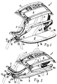
- the folding top for a convertible vehicle shown in the closed position in FIG. 1 consists of a hood frame 2 with a plurality of hoops and brackets, which are pivotably mounted with one another or on the vehicle body, and a top cloth 3, which is supported by the top frame 2 Closed position spans the vehicle interior.
- a rear area is the body-trunk of the vehicle with a storage space 4, which is part of the trunk and the folding top takes up in storage or opening position.
- a sunroof 6 consisting of a glass plate, which can be adjusted with the folding top closed between a closed and an open position.
- a tensioning bow 8 is arranged, which likewise forms part of the top linkage 2 and, when the vehicle roof is closed, ensures sufficient material tension in the cover material 3.
- the clamping bracket 8 is located directly behind body-mounted roll bars 7 and is approximately U-shaped with side legs 8a and 8b and a side leg connecting the transverse section 8c, wherein the end sides of the side legs 8a, 8b extend to the vehicle interior and the connecting cross section 8c closer to the rear lies. In the closed position of the folding top of the U-shaped clamping bracket is approximately in a horizontal plane.
- cover plate 9 In the space bounded by the side legs 8a and 8b and the rear cross section 8c of the tension bracket, one is fixed to the tension bracket connected cover plate 9 is taken, which completely fills the gap.
- the cover plate 9 is firmly connected to the clamping bracket 8 without possibility of relative movement.
- the cover plate 9 forms a hat rack, which extends horizontally in the vehicle interior underneath the top covering fabric 3 and behind the roll bars 7 and separates the vehicle interior from the storage space 4.
- the convertible top linkage 2 is held on a control console 10 which is pivotally mounted about a rotational axis 12 on the vehicle body via a rotary joint 11.
- a control console 10 and the clamping bracket 8 is rotatably supported via pivot joints 13 with extending in the transverse direction of rotation axis 14, wherein the pivot joints 13 adjacent to the end faces of the side legs 8a and 8b of the clamping bracket 8 are arranged.
- the axes of rotation 12 and 14 of control console 10 and clamping bracket 8 are parallel to each other and extend in the transverse direction, but are spaced from each other.
- the hinge 13 on the clamping bracket 8 is closer to the rear of the vehicle than the pivot 11 on the control console 10th
- the control console 10 For storage of the vehicle roof, the control console 10, as shown in Figures 2 and 3, pivoted about the axis of rotation 12 of the rotary joint 11 to the rear. At the same time the convertible top linkage 2 is folded and also pivoted in the direction of the vehicle rear.
- the rear clamping bracket 8 including recorded therein cover plate 9 approximately the horizontal position at what the clamping bracket 8 is pivoted about the rotation axis 14 of its pivot 13 in the opposite direction to the pivotal movement of the control console 10, so that the pivotal movement of the control console 10 is compensated, but at the same time the clamping bracket 8 including cover plate 9 is lowered vertically.
- the folding top 1 Upon reaching the storage position - Fig. 4 and Fig. 5 - the folding top 1 is completely in the storage space 4, wherein the cover plate 9 and the encompassing clamping bracket 8, the lower horizontal cover or the bottom of the form folded roof packages, so that cover plate 9 and clamping bracket 8 serve as a space divider between the freely usable area of the trunk and the storage space in the strict sense, in which the roof parts are stored.
- the roof parts form a superimposed folded roof part package with the lowermost cover plate 9 and clamping bracket 8 and on top lying front roof part, which includes the front roof cap 5 and the sunroof 6.
Landscapes
- Engineering & Computer Science (AREA)
- Mechanical Engineering (AREA)
- Seal Device For Vehicle (AREA)
- Tents Or Canopies (AREA)
- Vehicle Step Arrangements And Article Storage (AREA)
Abstract
Description
- Die Erfindung bezieht sich auf ein Cabriolet-Fahrzeug mit einem Faltverdeck nach dem Oberbegriff des Anspruches 1.
- Derartige Cabriolet-Fahrzeuge weisen ein zwischen einer Schließposition und einer Ablageposition verstellbares Faltverdeck auf, das einen üblicherweise textilen Verdeckbezugstoff auf einem verstellbaren Verdeckgestänge umfasst, wobei das Faltverdeck in Ablageposition in einem heckseitigen Verdeckkasten abgelegt wird. Dieser Verdeckkasten ist von einem Heckdeckel zu verschließen, der bei geschlossenem Faltverdeck von dem hinteren Abschnitt des Verdeckes überdeckt ist und eine in den Fahrzeuginnenraum einragende Hutablage bildet. Um dem Verdeckbezugstoff bei geschlossenem Dach die erforderliche Stoffspannung aufzuprägen, umfasst das Verdeckgestänge einen so genannten Spannbügel, an den der Verdeckbezugstoff angekoppelt ist und der in Schließposition des Daches eine auf dem Heckdeckel aufliegende Spannposition einnimmt.
- Zum Ablegen des Verdecks muss einerseits zunächst die Stoffspannung gelöst und andererseits der Verdeckkasten freigegeben werden. Hierfür wird der Spannbügel um ein karosserieseitiges Gelenk aufgeschwenkt, woraufhin der Heckdeckel geöffnet werden kann und der Zutritt in den Verdeckkasten freigegeben wird. Im Anschluss hieran wird das Faltverdeck in den Verdeckkasten abgelegt. Ein derartiges Fahrzeugdach wird beispielsweise in der
US 5,225,747 beschrieben. - Nachteilig bei dieser Ausführung ist, dass ein verhältnismäßig komplexer Bewegungsablauf zum Ablegen des Fahrzeugdaches durchgeführt werden muss. Zunächst muss der Spannbügel um eine karosserieseitige Querachse aufgestellt werden, damit der in Schließposition unter den Spannbügel reichende Heckdeckel aufgeschwenkt und hierdurch der Durchtritt in den Verdeckkasten für das Fahrzeugdach hinein freigegeben werden kann. Nach dem Aufschwenken des Heckdeckels wird der Spannbügel wieder abgesenkt und bis in den Verdeckkasten hinein verschwenkt; zugleich werden die weiteren Teile des Verdeckgestänges einschließlich des Verdeckbezugstoffes um ihre jeweiligen Schwenkachsen nach hinten geklappt und im Verdeckkasten abgelegt.
- Ein weiterer Nachteil ist darin zu sehen, dass der Verdeckkasten, in welchem das Fahrzeugdach abgelegt wird, einen Teil des Kofferraumes bildet, jedoch bei abgelegtem Fahrzeugdach keine Trennung zwischen dem Verdeckkasten und dem frei nutzbaren Teil des Kofferraumes existiert. Unter anderem aus Gründen des Schutzes des Faltverdecks ist aber eine derartige Trennung zwischen Verdeckkasten und frei nutzbarem Kofferraum wünschenswert.
- Der Erfindung liegt die Aufgabe zugrunde, mit einfachen konstruktiven Maßnahmen ein Cabriolet-Fahrzeug mit einem Faltverdeck dahingehend auszubilden, dass mit geringem Stellaufwand das Fahrzeugverdeck vom frei nutzbaren Kofferraum separiert ist.
- Diese Aufgabe wird erfindungsgemäß mit den Merkmalen des Anspruches 1 gelöst. Die Unteransprüche geben zweckmäßige Weiterbildungen an.
- Erfindungsgemäß ist vorgesehen, dass auf der dem Fahrzeuginnenraum zugewandten Seite des Spannbügels eine Abdeckplatte fest am Spannbügel gehalten ist, die in Schließposition zumindest näherungsweise eine horizontale Stellung einnimmt. Diese Abdeckplatte befindet sich in Schließposition innerhalb des Fahrzeugdaches und bildet eine Hutablage zwischen dem Fahrgastraum und dem Stauraum bzw. Verdeckkasten, in welchem das abgelegte Faltverdeck aufzunehmen ist. Aufgrund der festen Anbindung der Abdeckplatte an den Spannbügel ist eine gesonderte Stellkinematik für die Bewegung der Abdeckplatte nicht erforderlich; vielmehr wird die Abdeckplatte bei einer Stellbewegung des Spannbügels automatisch mit diesem bewegt.
- Diese Ausführung weist weiterhin den Vorteil auf, dass eine verhältnismäßig einfache Ablagebewegung für das Faltverdeck realisiert werden kann, da die Abdeckplatte als ein vom Kofferraum- bzw. Heckdeckel separates Bauteil ausgeführt ist und somit für die Überführung des Fahrzeugdaches von Schließ- in Ablageposition der Kofferraumdeckel angehoben werden kann, ohne den heckseitigen Spannbügel in eine angehobene Position aufschwenken zu müssen.
Vielmehr kann das Verdeckgestänge unter Vermeidung einer Aufschwenkbewegung unmittelbar nach hinten in den Stauraum abgeklappt werden. Gegebenenfalls kann es sogar ausreichend sein, auf eine Anhebung des Kofferraum- bzw. Heckdeckels zu verzichten und das Faltverdeck unmittelbar in den Stauraum zu versenken, wobei diese Ausführung sich für diejenigen Fälle eignet, dass der Stauraum zumindest im Wesentlichen von der Abdeckplatte überdeckt wird. - Aufgrund ihrer festen Position am Spannbügel wird die Abdeckplatte gemeinsam mit dem Spannbügel bei der Überführung von Schließ- in Ablageposition in den Verdeckkasten abgesenkt. Der Spannbügel als heckseitiges Gestängebauteil nimmt in Ablageposition eine unten liegende Stellung im Verdeckgestänge ein. Auch die Abdeckplatte nimmt diese Position ein, wobei gemäß einer vorteilhaften Weiterbildung vorgesehen ist, dass die Abdeckplatte in Ablageposition eine Trennwand zwischen dem Stauraum und dem frei nutzbaren Kofferraum bildet. Die Abdeckplatte bildet hierbei zweckmäßig den Boden des Stauraumes, derart, dass das Verdeckgestänge einschließlich Verdeckbezugstoff oberhalb der Abdeckplatte abgelegt ist. In dieser Ausführung nimmt die Abdeckplatte in Ablageposition eine horizontale Position ein und liegt etwa parallel zu ihrer Schließposition.
- Der Spannbügel ist vorteilhaft U-förmig ausgebildet und weist zwei Seitenschenkel auf, die über einen Querabschnitt verbunden sind, wobei der Querabschnitt das am weitesten hinten liegende, dem Heck zugewandte Bauteil des Fahrzeugdaches bildet. Der Spannbügel ist im Bereich der freien Enden seiner Seitenschenkel gelenkig gelagert, insbesondere schwenkbar an einer Stellkonsole gehalten, die ihrerseits schwenkbar an der Fahrzeugkarosserie gelagert ist, wobei die Schwenkachsen zwischen den Seitenschenkeln und der Stellkonsole einerseits und der Stellkonsole und der Fahrzeugkarosserie andererseits bei geschlossenem Fahrzeugdach zweckmäßig parallel, jedoch beabstandet zueinander sind. Zum Ablegen des Fahrzeugdaches wird die Stellkonsole um ihre karosserieseitige Drehachse nach unten in den Stauraum hinein verschwenkt, wobei der Spannbügel einschließlich der daran gehaltenen Abdeckplatte aufgrund des Drehgelenks zwischen den Seitenschenkeln und der Stellkonsole eine Ausgleichs-Schwenkbewegung in Gegenrichtung zur Konsolenbewegung ausführen kann, wodurch die etwa horizontale Lage des Spannbügels und der Abdeckplatte auch in Ablageposition beibehalten werden kann.
- Weitere Vorteile und zweckmäßige Ausführungen sind den weiteren Ansprüchen, der Figurenbeschreibung und den Zeichnungen zu entnehmen. Es zeigen:
- Fig. 1
- eine perspektivische Ansicht eines Faltverdecks für ein Cabriolet-Fahrzeug, dargestellt in Schließposition, in der der Fahrzeuginnenraum von dem Faltverdeck überdeckt ist, mit einem heckseitigen Spannbügel, an dem eine Abdeckplatte befestigt ist,
- Fig. 2
- das Faltverdeck zu Beginn der Ablagebewegung,
- Fig. 3
- das Faltverdeck kurz vor Erreichen der Ablageposition,
- Fig. 4
- das Faltverdeck in Ablageposition,
- Fig. 5
- das Faltverdeck in Ablageposition aus einer anderen Perspektive.
- In den Figuren sind gleiche Bauteile mit gleichen Bezugszeichen versehen.
- Das in Fig. 1 in Schließposition dargestellte Faltverdeck für ein Cabriolet-Fahrzeug besteht aus einem Verdeckgestänge 2 mit einer Mehrzahl von Spriegeln und Bügeln, die untereinander bzw. an der Fahrzeugkarosserie schwenkbar gelagert sind, und einem von dem Verdeckgestänge 2 getragenen Verdeckbezugstoff 3, der in Schließposition den Fahrzeuginnenraum überspannt. Im Heckbereich befindet sich der karosseriefeste Kofferraum des Fahrzeuges mit einem Stauraum 4, der Bestandteil des Kofferraumes ist und das Faltverdeck in Ablage- bzw. Öffnungsposition aufnimmt. In einem vorderen Abschnitt des Faltverdecks 1 befindet sich benachbart zur vorderen Dachkappe 5, die in Schließposition am Windschutzscheibenrahmen anliegt, ein Schiebedach 6, bestehend aus einer Glasplatte, die bei geschlossenem Faltverdeck zwischen einer Schließ- und einer Öffnungsposition verstellt werden kann.
- In dem dem Fahrzeugheck zugewandten Bereich des Daches ist ein Spannbügel 8 angeordnet, welcher ebenfalls Bestandteil des Verdeckgestänges 2 ist und bei geschlossenem Fahrzeugdach für eine ausreichende Stoffspannung im Bezugstoff 3 sorgt. Der Spannbügel 8 liegt unmittelbar hinter karosseriefesten Überrollbügeln 7 und ist näherungsweise U-förmig mit Seitenschenkeln 8a und 8b und einem die Seitenschenkel verbindenden Querabschnitt 8c ausgebildet, wobei die Stirnseiten der Seitenschenkel 8a, 8b sich zum Fahrzeuginnenraum hin erstrecken und der verbindende Querabschnitt 8c näher am Heck liegt. In Schließposition des Faltverdecks liegt der U-förmige Spannbügel etwa in einer horizontalen Ebene. In dem Zwischenraum, der von den Seitenschenkeln 8a und 8b sowie dem hinteren Querabschnitt 8c des Spannbügels begrenzt wird, ist eine fest mit dem Spannbügel verbundene Abdeckplatte 9 aufgenommen, die den Zwischenraum vollständig ausfüllt. Die Abdeckplatte 9 ist ohne Möglichkeit einer Relativbewegung fest mit dem Spannbügel 8 verbunden. Die Abdeckplatte 9 bildet bei geschlossenem Fahrzeugdach eine Hutablage, die sich unterhalb des Verdeckbezugsstoffes 3 und hinter den Überrollbügeln 7 horizontal im Fahrzeuginnenraum erstreckt und den Fahrzeuginnenraum von dem Stauraum 4 separiert.
- Das Verdeckgestänge 2 ist an einer Stellkonsole 10 gehalten, die über ein Drehgelenk 11 schwenkbar um eine Rotationsachse 12 an der Fahrzeugkarosserie gelagert ist. An dieser Stellkonsole 10 ist auch der Spannbügel 8 über Drehgelenke 13 mit in Querrichtung verlaufender Rotationsachse 14 drehbar gehalten, wobei die Drehgelenke 13 benachbart zu den Stirnseiten der Seitenschenkel 8a und 8b des Spannbügels 8 angeordnet sind. Die Rotationsachsen 12 und 14 von Stellkonsole 10 und Spannbügel 8 liegen parallel zueinander und verlaufen in Querrichtung, sind jedoch zueinander beabstandet. Das Drehgelenk 13 am Spannbügel 8 liegt näher am Fahrzeugheck als das Drehgelenk 11 an der Stellkonsole 10.
- Zur Ablage des Fahrzeugdaches wird die Stellkonsole 10, wie in den Figuren 2 und 3 dargestellt, um die Rotationsachse 12 des Drehgelenkes 11 nach hinten verschwenkt. Zugleich wird das Verdeckgestänge 2 zusammengefaltet und ebenfalls in Richtung Fahrzeugheck verschwenkt. Während der Ablagebewegung behält der hintere Spannbügel 8 einschließlich darin aufgenommener Abdeckplatte 9 die horizontale Position näherungsweise bei, wofür der Spannbügel 8 um die Rotationsachse 14 seines Drehgelenkes 13 in Gegenrichtung zur Schwenkbewegung der Stellkonsole 10 verschwenkt wird, so dass die Schwenkbewegung der Stellkonsole 10 kompensiert wird, zugleich aber der Spannbügel 8 einschließlich Abdeckplatte 9 vertikal abgesenkt wird.
- Mit Erreichen der Ablageposition - Fig. 4 und Fig. 5 - liegt das Faltverdeck 1 vollständig im Stauraum 4, wobei die Abdeckplatte 9 und der umgreifende Spannbügel 8 die untere, horizontale Abdeckung bzw. den Boden des zusammengefalteten Dachpaketes bilden, so dass Abdeckplatte 9 und Spannbügel 8 als Raumteiler zwischen dem frei nutzbaren Bereich des Kofferraumes und dem Stauraum im engeren Sinne dienen, in welchem die Dachteile abgelegt sind.
- In Ablageposition bilden die Dachteile ein übereinander gefaltetes Dachteilpaket mit der zuunterst liegenden Abdeckplatte 9 und Spannbügel 8 und obenauf liegendem vorderen Dachteil, welches die vordere Dachkappe 5 und das Schiebedach 6 umfasst.
-
- 1
- Faltverdeck
- 2
- Verdeckgestänge
- 3
- Bezugstoff
- 4
- Stauraum
- 5
- Dachkappe
- 6
- Schiebedach
- 7
- Überrollbügel
- 8
- Spannbügel
- 8a
- Seitenschenkel
- 8b
- Seitenschenkel
- 8c
- Querabschnitt
- 9
- Abdeckplatte
- 10
- Stellkonsole
- 11
- Drehgelenk
- 12
- Rotationsachse
- 13
- Drehgelenk
- 14
- Rotationsachse
Claims (10)
- Cabriolet-Fahrzeug mit einem Faltverdeck (1), bestehend aus einem Verdeckgestänge (2) und einem vom Verdeckgestänge (2) getragenen Verdeckbezugstoff (3), wobei das Faltverdeck (1) zwischen einer Schließposition und einer Ablageposition verstellbar und in Ablageposition in einem heckseitigen Stauraum (4) abgelegt ist, und wobei das Verdeckgestänge (2) einen Spannbügel (8) umfasst, der in Schließposition des Faltverdecks (1) den Verdeckbezugstoff (3) mit Spannung beaufschlagt,
dadurch gekennzeichnet,
dass auf der dem Fahrzeuginnenraum zugewandten Seite des Spannbügels (8) eine Abdeckplatte (9) fest am Spannbügel (8) gehalten ist, die in Schließposition zumindest näherungsweise eine horizontale Stellung einnimmt, wobei die Abdeckplatte (9) bei der Überführung des Faltverdecks (1) zwischen Schließ- und Ablageposition gemeinsam mit dem Spannbügel (8) relativ zur Fahrzeugkarosserie zu verstellen ist. - Cabriolet-Fahrzeug nach Anspruch 1,
dadurch gekennzeichnet,
dass der Spannbügel (8) näherungsweise U-Form mit zwei Seitenschenkeln (8a, 8b) und einem die Seitenschenkel (8a, 8b) verbindenden Querabschnitt (8c) aufweist und in Schließposition eine näherungsweise horizontale Stellung einnimmt, wobei die Abdeckplatte (9) im Zwischenraum zwischen den Seitenschenkeln (8a, 8b) und dem Querabschnitt (8c) angeordnet ist. - Cabriolet-Fahrzeug nach Anspruch 2,
dadurch gekennzeichnet,
dass die Abdeckplatte (9) die U-Form des Spannbügels (8) zumindest näherungsweise ausfüllt. - Cabriolet-Fahrzeug nach einem der Ansprüche 1 bis 3,
dadurch gekennzeichnet,
dass die Abdeckplatte (9) in Schließposition des Fahrzeugdaches den Stauraum (4) vom Kofferraum des Fahrzeuges separiert. - Cabriolet-Fahrzeug nach einem der Ansprüche 1 bis 4,
dadurch gekennzeichnet,
dass die Abdeckplatte (9) in Ablageposition des Fahrzeugdaches den Stauraum (4) vom Kofferraum separiert. - Cabriolet-Fahrzeug nach einem der Ansprüche 1 bis 5,
dadurch gekennzeichnet,
dass die Abdeckplatte (9) in Ablageposition den Boden des Stauraumes (4) bildet. - Cabriolet-Fahrzeug nach einem der Ansprüche 1 bis 6,
dadurch gekennzeichnet,
dass der Spannbügel (8) an einer Stellkonsole (10) gehalten ist, die schwenkbar an der Fahrzeugkarosserie gelagert ist. - Cabriolet-Fahrzeug nach einem der Ansprüche 1 bis 7,
dadurch gekennzeichnet,
dass die Abdeckplatte (9) in Schließposition zumindest näherungsweise parallel zu ihrer Lage in Ablageposition steht. - Cabriolet-Fahrzeug nach einem der Ansprüche 1 bis 8,
dadurch gekennzeichnet,
dass der Spannbügel (8) über eine Mehrgelenkkinematik an die Fahrzeugkarosserie gekoppelt ist. - Cabriolet-Fahrzeug nach einem der Ansprüche 1 bis 9,
dadurch gekennzeichnet,
dass die Abdeckplatte (9) in Schließposition eine Hutablage bildet.
Applications Claiming Priority (1)
| Application Number | Priority Date | Filing Date | Title |
|---|---|---|---|
| DE102006008124A DE102006008124B3 (de) | 2006-02-20 | 2006-02-20 | Cabriolet-Fahrzeug mit einem Faltverdeck |
Publications (1)
| Publication Number | Publication Date |
|---|---|
| EP1820680A1 true EP1820680A1 (de) | 2007-08-22 |
Family
ID=38042920
Family Applications (1)
| Application Number | Title | Priority Date | Filing Date |
|---|---|---|---|
| EP07002795A Ceased EP1820680A1 (de) | 2006-02-20 | 2007-02-09 | Cabriolet-Fahrzeug mit einem Faltverdeck |
Country Status (4)
| Country | Link |
|---|---|
| US (1) | US20070194595A1 (de) |
| EP (1) | EP1820680A1 (de) |
| JP (1) | JP2007223592A (de) |
| DE (1) | DE102006008124B3 (de) |
Cited By (1)
| Publication number | Priority date | Publication date | Assignee | Title |
|---|---|---|---|---|
| DE102008010804A1 (de) * | 2008-02-23 | 2009-09-10 | Wilhelm Karmann Gmbh | Cabriolet-Fahrzeug mit einem Verdeckkastendeckel |
Families Citing this family (7)
| Publication number | Priority date | Publication date | Assignee | Title |
|---|---|---|---|---|
| DE10349822A1 (de) * | 2003-10-24 | 2005-06-02 | Wilhelm Karmann Gmbh | Cabriolet-Fahrzeug |
| DE10349821B4 (de) * | 2003-10-24 | 2005-11-24 | Wilhelm Karmann Gmbh | Cabriolet-Fahrzeug |
| DE10357098B3 (de) * | 2003-12-06 | 2005-05-25 | Wilhelm Karmann Gmbh | Cabriolet-Fahrzeug |
| US7959208B2 (en) * | 2008-12-22 | 2011-06-14 | Wilhelm Karmann Gmbh | Convertible top with in-folding side rails |
| DE102016007982A1 (de) | 2016-06-30 | 2018-01-04 | Daimler Ag | Verdeckgestänge für ein Verdeck eines offenen Personenkraftwagens |
| CN114475183B (zh) * | 2022-01-14 | 2024-01-12 | 重庆长安汽车股份有限公司 | 一种用于敞篷车辆的篷布折叠机构及敞篷车辆 |
| USD1002493S1 (en) * | 2022-02-16 | 2023-10-24 | Bestop, Inc. | Convertible top frame |
Citations (3)
| Publication number | Priority date | Publication date | Assignee | Title |
|---|---|---|---|---|
| US5225747A (en) * | 1992-01-06 | 1993-07-06 | Asc Incorporated | Single-button actuated self-correcting automatic convertible top |
| EP0733505A1 (de) * | 1995-03-21 | 1996-09-25 | Applied Power Inc. | Kraftfahrzeug mit Faltdach und Faltdach für ein solches Fahrzeug |
| WO2005102756A1 (de) * | 2004-04-27 | 2005-11-03 | Wilhelm Karmann Gmbh | Cabrioletvorrichtung für ein fahrzeug |
Family Cites Families (4)
| Publication number | Priority date | Publication date | Assignee | Title |
|---|---|---|---|---|
| DE19912358B4 (de) * | 1999-03-19 | 2005-02-03 | Wilhelm Karmann Gmbh | Cabriolet-Fahrzeug |
| DE19963668B4 (de) * | 1999-12-29 | 2005-01-13 | Wilhelm Karmann Gmbh | Cabriolet-Fahrzeug |
| US6966599B2 (en) * | 2003-06-30 | 2005-11-22 | Asc Incorporated | Convertible roof apparatus with power roof bow linked to a tensioning bow |
| DE10331392B3 (de) * | 2003-07-11 | 2005-03-10 | Karmann Gmbh W | Zwischen der Heckklappe und dem den Hinterrand eines Faltverdeckes eines Cabriolet-Fahrzeugs abspannenenden Spannbügel angeordnete Gelenkvorrichtung |
-
2006
- 2006-02-20 DE DE102006008124A patent/DE102006008124B3/de not_active Expired - Fee Related
-
2007
- 2007-02-09 EP EP07002795A patent/EP1820680A1/de not_active Ceased
- 2007-02-20 JP JP2007039247A patent/JP2007223592A/ja active Pending
- 2007-02-20 US US11/676,594 patent/US20070194595A1/en not_active Abandoned
Patent Citations (3)
| Publication number | Priority date | Publication date | Assignee | Title |
|---|---|---|---|---|
| US5225747A (en) * | 1992-01-06 | 1993-07-06 | Asc Incorporated | Single-button actuated self-correcting automatic convertible top |
| EP0733505A1 (de) * | 1995-03-21 | 1996-09-25 | Applied Power Inc. | Kraftfahrzeug mit Faltdach und Faltdach für ein solches Fahrzeug |
| WO2005102756A1 (de) * | 2004-04-27 | 2005-11-03 | Wilhelm Karmann Gmbh | Cabrioletvorrichtung für ein fahrzeug |
Cited By (1)
| Publication number | Priority date | Publication date | Assignee | Title |
|---|---|---|---|---|
| DE102008010804A1 (de) * | 2008-02-23 | 2009-09-10 | Wilhelm Karmann Gmbh | Cabriolet-Fahrzeug mit einem Verdeckkastendeckel |
Also Published As
| Publication number | Publication date |
|---|---|
| DE102006008124B3 (de) | 2007-07-05 |
| JP2007223592A (ja) | 2007-09-06 |
| US20070194595A1 (en) | 2007-08-23 |
Similar Documents
| Publication | Publication Date | Title |
|---|---|---|
| DE4441666C1 (de) | Faltverdeck für ein Fahrzeug | |
| EP1737689B1 (de) | Faltverdeck für ein cabriolet-fahrzeug sowie cabriolet-fahrzeug mit einem faltverdeck | |
| DE29812165U1 (de) | Cabriolet-Fahrzeug mit einem Verdeckkasten | |
| EP1826049A2 (de) | Cabriolet-Fahrzeug mit einem Hardtop-Fahrzeugdach | |
| DE19912358A1 (de) | Cabriolet-Fahrzeug | |
| DE102005047846B3 (de) | Fahrzeugdach für ein Cabriolet-Fahrzeug mit einer verschwenkbaren Dachkappe | |
| DE102004055991B3 (de) | Verstellbares Fahrzeugdach mit einem Stoffverdeck | |
| WO2005047037A1 (de) | Fahrzeug, insbesondere pkw, mit aufbauöffnungen | |
| DE10220770C1 (de) | Cabriolet-Fahrzeug mit einem rückwärtigen Stauraum für das Verdeck | |
| DE19752068A1 (de) | Dachaufbau für Fahrzeuge | |
| DE102006008124B3 (de) | Cabriolet-Fahrzeug mit einem Faltverdeck | |
| DE102018117521B4 (de) | Fahrzeugaufbau mit starrem Verdeckelement und öffenbarer Heckscheibe | |
| EP0429777A2 (de) | Klappverdeck für ein Kraftfahrzeug | |
| DE10242502B4 (de) | Verstellbares Fahrzeugdach | |
| DE102007004180B4 (de) | Verstellbares Fahrzeugdach | |
| DE10242501B4 (de) | Fahrzeugdach für ein Cabriolet-Fahrzeug | |
| EP3225444B1 (de) | Verdeck mit ablageraumdeckel | |
| DE102006006686A1 (de) | Kompakt ablegbares Faltverdeck eines Kraftfahrzeugs | |
| DE19610969C2 (de) | Klappverdeck für Personenkraftwagen | |
| DE102005043512B3 (de) | Steilheckfahrzeug mit offenem Aufbau | |
| EP1910114B1 (de) | Cabriolet-fahrzeug | |
| EP1588881A1 (de) | Kraftfahrzeug mit beweglichen Dachteilen | |
| DE102014106266A1 (de) | Faltverdeck mit Absenkhebel für Spannbügel | |
| DE202011101123U1 (de) | Verstellbares Fahrzeugdach mit einem ausfahrbaren Überrollbügel | |
| DE102011102508B4 (de) | Faltbares Verdeck für ein Cabriolet-Fahrzeug |
Legal Events
| Date | Code | Title | Description |
|---|---|---|---|
| PUAI | Public reference made under article 153(3) epc to a published international application that has entered the european phase |
Free format text: ORIGINAL CODE: 0009012 |
|
| AK | Designated contracting states |
Kind code of ref document: A1 Designated state(s): AT BE BG CH CY CZ DE DK EE ES FI FR GB GR HU IE IS IT LI LT LU LV MC NL PL PT RO SE SI SK TR |
|
| AX | Request for extension of the european patent |
Extension state: AL BA HR MK YU |
|
| 17P | Request for examination filed |
Effective date: 20080207 |
|
| AKX | Designation fees paid |
Designated state(s): DE FR GB IT |
|
| 17Q | First examination report despatched |
Effective date: 20080515 |
|
| STAA | Information on the status of an ep patent application or granted ep patent |
Free format text: STATUS: THE APPLICATION HAS BEEN REFUSED |
|
| 18R | Application refused |
Effective date: 20090306 |