EP1820698B1 - Appareil embarqué - Google Patents
Appareil embarqué Download PDFInfo
- Publication number
- EP1820698B1 EP1820698B1 EP07003357.6A EP07003357A EP1820698B1 EP 1820698 B1 EP1820698 B1 EP 1820698B1 EP 07003357 A EP07003357 A EP 07003357A EP 1820698 B1 EP1820698 B1 EP 1820698B1
- Authority
- EP
- European Patent Office
- Prior art keywords
- lid
- apparatus body
- front surface
- surface part
- microphone
- Prior art date
- Legal status (The legal status is an assumption and is not a legal conclusion. Google has not performed a legal analysis and makes no representation as to the accuracy of the status listed.)
- Expired - Fee Related
Links
Images








Classifications
-
- G—PHYSICS
- G11—INFORMATION STORAGE
- G11B—INFORMATION STORAGE BASED ON RELATIVE MOVEMENT BETWEEN RECORD CARRIER AND TRANSDUCER
- G11B31/00—Arrangements for the associated working of recording or reproducing apparatus with related apparatus
-
- B—PERFORMING OPERATIONS; TRANSPORTING
- B60—VEHICLES IN GENERAL
- B60R—VEHICLES, VEHICLE FITTINGS, OR VEHICLE PARTS, NOT OTHERWISE PROVIDED FOR
- B60R11/00—Arrangements for holding or mounting articles, not otherwise provided for
- B60R11/02—Arrangements for holding or mounting articles, not otherwise provided for for radio sets, television sets, telephones, or the like; Arrangement of controls thereof
-
- B—PERFORMING OPERATIONS; TRANSPORTING
- B60—VEHICLES IN GENERAL
- B60R—VEHICLES, VEHICLE FITTINGS, OR VEHICLE PARTS, NOT OTHERWISE PROVIDED FOR
- B60R11/00—Arrangements for holding or mounting articles, not otherwise provided for
- B60R11/02—Arrangements for holding or mounting articles, not otherwise provided for for radio sets, television sets, telephones, or the like; Arrangement of controls thereof
- B60R11/0247—Arrangements for holding or mounting articles, not otherwise provided for for radio sets, television sets, telephones, or the like; Arrangement of controls thereof for microphones or earphones
-
- G—PHYSICS
- G11—INFORMATION STORAGE
- G11B—INFORMATION STORAGE BASED ON RELATIVE MOVEMENT BETWEEN RECORD CARRIER AND TRANSDUCER
- G11B33/00—Constructional parts, details or accessories not provided for in the other groups of this subclass
- G11B33/02—Cabinets; Cases; Stands; Disposition of apparatus therein or thereon
- G11B33/027—Covers
-
- H—ELECTRICITY
- H04—ELECTRIC COMMUNICATION TECHNIQUE
- H04M—TELEPHONIC COMMUNICATION
- H04M1/00—Substation equipment, e.g. for use by subscribers
- H04M1/60—Substation equipment, e.g. for use by subscribers including speech amplifiers
- H04M1/6033—Substation equipment, e.g. for use by subscribers including speech amplifiers for providing handsfree use or a loudspeaker mode in telephone sets
- H04M1/6041—Portable telephones adapted for handsfree use
- H04M1/6075—Portable telephones adapted for handsfree use adapted for handsfree use in a vehicle
- H04M1/6083—Portable telephones adapted for handsfree use adapted for handsfree use in a vehicle by interfacing with the vehicle audio system
- H04M1/6091—Portable telephones adapted for handsfree use adapted for handsfree use in a vehicle by interfacing with the vehicle audio system including a wireless interface
-
- B—PERFORMING OPERATIONS; TRANSPORTING
- B60—VEHICLES IN GENERAL
- B60R—VEHICLES, VEHICLE FITTINGS, OR VEHICLE PARTS, NOT OTHERWISE PROVIDED FOR
- B60R11/00—Arrangements for holding or mounting articles, not otherwise provided for
- B60R11/02—Arrangements for holding or mounting articles, not otherwise provided for for radio sets, television sets, telephones, or the like; Arrangement of controls thereof
- B60R11/0264—Arrangements for holding or mounting articles, not otherwise provided for for radio sets, television sets, telephones, or the like; Arrangement of controls thereof for control means
-
- B—PERFORMING OPERATIONS; TRANSPORTING
- B60—VEHICLES IN GENERAL
- B60R—VEHICLES, VEHICLE FITTINGS, OR VEHICLE PARTS, NOT OTHERWISE PROVIDED FOR
- B60R11/00—Arrangements for holding or mounting articles, not otherwise provided for
- B60R2011/0042—Arrangements for holding or mounting articles, not otherwise provided for characterised by mounting means
- B60R2011/008—Adjustable or movable supports
-
- B—PERFORMING OPERATIONS; TRANSPORTING
- B60—VEHICLES IN GENERAL
- B60R—VEHICLES, VEHICLE FITTINGS, OR VEHICLE PARTS, NOT OTHERWISE PROVIDED FOR
- B60R11/00—Arrangements for holding or mounting articles, not otherwise provided for
- B60R11/02—Arrangements for holding or mounting articles, not otherwise provided for for radio sets, television sets, telephones, or the like; Arrangement of controls thereof
- B60R2011/0294—Apparatus with multi-functionalities, e.g. radio and telephone
Definitions
- the present invention relates to an in-vehicle apparatus.
- the hands-free conversation system has a microphone for picking up a sound (voice) and a speaker for generating a sound (voice), which are connected to a cellular phone through a wired circuit or a wireless circuit so as to enable communication.
- the user can perform hands-free conversation in the compartment by use of the microphone and the speaker.
- the in-vehicle apparatus is incorporated in a dashboard, a center console panel or the like provided in a vehicle compartment, and the microphone is attached to a location, remote from the in-vehicle apparatus, in the vehicle compartment or to a location where the in-vehicle apparatus fronts on the vehicle compartment.
- the microphone is attached to a location, remote from the in-vehicle apparatus, in the vehicle compartment, it is unnecessary to incorporate the microphone in the case of the in-vehicle apparatus, which is advantageous from the viewpoint of securing the degree of freedom in designing the case.
- the microphone and the in-vehicle apparatus are connected to each other by a wiring member, there is need for the laying space for the wiring member. Besides, there is a disadvantage that laying-around of the wiring member is intricate.
- the problems concerning the laying space for the wiring member and laying-around of the wiring member are dissolved.
- the appearance surface (design surface) of the in-vehicle apparatus with a hole or opening for guiding the sound to the microphone, which is disadvantageous from the viewpoint of enhancing the appearance quality and enhancing the degree of freedom in design.
- FIG. 1 is a perspective view of an in-vehicle apparatus 10 according to this embodiment of the present invention
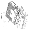
- FIG. 2 is a view showing the condition where a lid 16 is detached from an apparatus body 12 of the in-vehicle apparatus 10
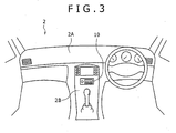
- FIG. 3 illustrates the condition where the in-vehicle apparatus 10 is installed in a vehicle compartment
- FIG. 4 is a block diagram showing the configuration of a control system in the in-vehicle apparatus 10.
- the in-vehicle apparatus 10 in this embodiment is a car audio system used in the manner of loading and unloading a disk-formed recording medium (optical disk) such as CD, MD, DVD, etc., and the car audio system is provided with a hands-free conversation system for performing hands-free conversation through a cellular phone 90.
- a disk-formed recording medium optical disk
- the car audio system is provided with a hands-free conversation system for performing hands-free conversation through a cellular phone 90.
- the in-vehicle apparatus 10 includes the apparatus body 12, and the lid 16 for opening and closing a front surface 14 of the apparatus body 12.
- the apparatus body 12 is incorporated in a location of a vehicle body, such as a dashboard 2A and a center console panel 2B located in the vehicle compartment 2, and the front surface 14 of the apparatus body 12 is set fronting on the vehicle compartment 2.
- a main part of the car audio system includes, for example, a reproduction unit 1002, a tuner unit 1004, an audio output unit 1006, an audio input unit 1008, an operating unit 1010, a display unit 1012, a control unit 1014 and the like.
- the reproduction unit 1002 is a unit for reproduction of data, such as audio data, recorded on the disk-formed recording medium D such as CD, MD, DVD, etc. and for outputting an audio signal or the like.
- a recording/reproduction unit for recording and reproduction of data on the disk-formed recording medium D may be provided, in place of the reproduction unit 1002.
- the tuner unit 1004 is a unit for receiving electromagnetic waves such as AM waves and FM waves transmitted from radio broadcasting stations and for outputting an audio signal.
- the audio output unit 1006 is a unit for applying predetermined signal processings inclusive of amplification to the audio signal supplied through the control unit 1014 and for supplying the processed signal to a speaker 18 incorporated in the vehicle compartment 2, to thereby generate a sound from the speaker 18.
- the audio input unit 1008 is a unit for applying predetermined signal processings inclusive of amplification to an audio signal supplied through a microphone 20 incorporated in the apparatus body 12 and for supplying the processed signal to the control unit 1014.
- the operating unit 1010 is a unit operated to give commands for operations of the reproduction unit 1002, the tuner unit 1004, the audio output unit 1006, and the audio input unit 1008, and control signals according to operations on the operating unit 1010 are supplied to the control unit 1014.
- the display unit 1012 is a unit for displaying the operating conditions of the reproduction unit 1002, the tuner unit 1004, the audio output unit 1006, the audio input unit 1008 and the like by use of characters, symbols, icons, or images or the like, based on the control conducted by the control unit 1014.
- the control unit 1014 is a unit for controlling the reproduction unit 1002, the tuner unit 1004, the audio output unit 1006, the audio input unit 1008, the operating unit 1010, and the display unit 1012.
- the reproduction unit 1002, the tuner unit 1004, the audio output unit 1006, the audio input unit 1008, and the control unit 1014 are provided in the apparatus body 12, while the operating unit 1010 and the display unit 1012 are provided in the lid 16.
- the hands-free conversation system includes the speaker 18, the microphone 20, the audio output unit 1006, the audio input unit 1008, a radiocommunication unit 1020, and the control unit 1014.
- the radiocommunication unit 1020 is for performing communication (talking) by radio between itself and a radiocommunication unit 9002 provided in a cellular phone 90 carried by the user.
- the radiocommunication units 1020 and 9002 are provided respectively with antennas 1021 and 9003 for Bluetooth radiocommunication.
- the Bluetooth radiocommunication is used as radiocommunication.
- other radiocommunications than the Bluetooth radiocommunication, radiocommunication using IR rays or the like may also be naturally adopted as radiocommunication.
- the cellular phone 90 is brought into the vehicle compartment 2 by the user.
- a communication line is established between the cellular phone 90 and a telephone set 94 on the other end side of line through a public telephone network 92 in the condition where a communication line is established through the radiocommunication unit 9002 in the cellular phone 90 and the radiocommunication unit 1020 of the hands-free conversation system
- hands-free conversation can be made with the telephone set 94 on the other end side of line by use of the hands-free conversation system.
- the telephone set 94 on the other end side of line may naturally be a cellular phone or a fixed telephone set.
- control unit 1014 so controls that voice (sound) transmitted from the telephone set 94 on the other end side of line through the public telephone network 92 and the radiocommunication units 9002, 1020 is received and is generated as voice by the audio output unit 1006 and the speaker 18, whereas the user's voice is transmitted to the telephone set 94 on the other end side of line through the microphone 20, the audio input unit 1008, the radiocommunication units 1020, 9002 and the public telephone network 92.
- the speaker 18 constitutes a part of a receiver unit for listening the voice in the hands-free system
- the microphone 20 constitutes a part of a transmitter unit for picking up the voice in the hands-free system.
- the apparatus body 2 has a casing 22 assuming a flat regular parallelopiped shape.
- the front surface 14 of the apparatus body 12 is an outside surface 24 of a front panel 24 constituting a front part of the casing 22, and, as shown in FIG. 6 , the front panel 24 has an inside surface 24B fronting on the inside of the casing 22.
- the front surface 14 has a rectangular shape elongate in the left-right direction.
- the front surface 14 is provided with a loading/unloading gate 26 for the disk-formed recording medium, and with an apparatus body side connector 28 connected to the control unit 1014.
- the front surface 14 has a horizontally elongate front surface part 1402, and a side surface part 1404 rising from the periphery of the front surface part 1402.
- the front panel 24 is composed of a molding of a synthetic resin material.
- a synthetic resin material for example, an ABS resin can be used.
- the lid 16 is for opening and closing the front surface 14 of the apparatus body 12.
- the lid 16 has a back surface 30 fronting on the front surface 14 of the apparatus body 12 in the state of closing the front surface 14, and a front surface 32 fronting on the inside of the vehicle compartment 2 (i.e., fronting on the outside of the apparatus body 12).
- the back surface 30 of the lid 16 has a back surface part 3002 fronting on the front surface part 1402, and a side surface part 3004 rising from the periphery of the back surface part 3002 and fronting on the side surface part 1404.
- a plurality of operating members 17 for operating the apparatus body 12 are disposed at the front surface of the lid 16, and the operating members 17 constitute the operating unit 1010.
- the operating members 17 include a volume control 1702 for controlling the volume of the sound generated from the speaker 18, operating switches 1704 for starting and stopping of reproduction of the disk-formed recording medium D, selection of a tune, fast forward feed, fast reverse feed, and ejection of the disk-formed recording medium D, etc., and tuning switches 1706 for tuning in the tuner unit 1004.
- the operating members 17 further include a reception switch 1708 for performing a reception operation in the hands-free conversation, and a talk end switch 1709 for performing a talk ending operation in the hands-free conversation, and the like.
- a lid-side connector 33 is provided at the back surface 30 of the lid 16. As shown in FIG. 4 , the lid-side connector 33 is engaged with the apparatus body side connector 28 in the condition where the front surface 14 is closed with the lid 16, and the lid-side connector 33 is disengaged from the apparatus body side connector 28 in the condition where the lid 16 is detached from the front surface 14.
- the lid-side connector 33 has a plurality of contact pieces electrically connected to the operating members 17 and the display unit 1012, and the apparatus body side connector 28 has a plurality of contact pieces electrically connected to the control unit 1014.
- the contact pieces of the lid-side connector 33 are electrically connected to the contact pieces of the apparatus body side connector 28, whereby control signals are transferred between the control unit 1014 and the operating members 17 and the display unit 1012.
- the lid 16 may be provided to be non-detachable or be detachable from the front surface 14 of the apparatus body 12.
- the lid 16 is provided to be non-detachable from the front surface 14
- various known configurations such as a a system in which the lid 16 is swingable and a system in which the lid 16 is slidable.
- the lid 16 provided to be detachable there are provided various known configurations such as a system in which the lid 16 is swingable or is slidable, in the condition where the lid 16 is connected to the front surface 14 of the apparatus body 12.
- FIGS. 1 and 2 show an example in which the lid 16 is provided to be detachable from the apparatus body 12.
- flanges 1410 are provided projectingly from lower parts on both left and right sides of the front surface 14
- shafts 1412 are projectingly provided at the tip ends of the left and right flanges 1410, and the shafts 1412 are disengageably joined to shaft receiving holes 1610 in lower parts of left and right side surfaces of the lid 16, whereby the lid 16 can be swung about the shafts 1412.
- a lock pawl 1414 is engaged with an upper part of the lid 16, and the closed state of the front surface 14 is maintained.
- the lock pawl 1414 With an unlocking button depressed, the lock pawl 1414 is disengaged, to permit the lid 16 to be swingable in the direction of spacing away from the front surface 14, whereby an opened state of the front surface is obtained.
- This detachable system is advantageous from the viewpoint of detaching the lid 16 from the apparatus body 12 when the user departs from the automobile, so as to prevent the in-vehicle apparatus 10 from being stolen.
- FIGS. 17 and 18 show an example in which the lid 16 is non-detachable from the apparatus body 12 and in which a lower part of the lid 16 is swingably connected to a lower part of the apparatus body 12.
- flanges 1420 are provided projectingly from lower parts on both left and right sides of the front surface 14, the tip ends of the left and right flanges 1420 are connected to lower parts of left and right side surfaces of the lid 16 through shafts 1422, and the lid 16 is swung about the shafts 1422, so as to open and close the front surface 14.
- FIGS. 19 and 20 show a modification of the example shown in FIGS. 1 and 2 , in which the lid 16 is provided to be detachable from the apparatus body 12.
- a lock pawl 1425 is engaged with a left side part of the lid 16, whereby the closed state of the front surface 14 as shown in FIGS. 1 and 17 is maintained.
- the lock pawl 1425 is disengaged, to permit the lid 16 to be swung with a lock piece 1427 at a right side part of the apparatus body 12 as a fulcrum; then, with an engaging part of the lid 16 disengaged from the lock piece 1427, the lid 16 is detached.
- FIGS. 21 and 22 show an example in which the lid 16 is slidable relative to the front surface 14.
- an upper link 1430 and the front end of a lower link 1432 are rotatably supported respectively by upper and lower parts of both left and right side parts of the back surface 30 of the lid 16.
- the rear end of the upper link 1430 and the rear end of the lower link 1432 are engaged with guide grooves 1434 formed in the apparatus body 12.
- the opening of the front surface 14 starting from the closed state of the front surface 14 is conducted by sliding a lower part of the lid 16 to the front side, moving an upper part of the lid 16 downwards along the front surface of the apparatus body 12 and locating the upper part of the lid 16 to the front side of a lower part of the front surface 14.
- the closing of the front surface 14 starting from the opened state of the front surface 14 is conducted, in reverse to the above, by sliding the lower part of the lid 16 to the rear side, and moving the upper part of the lid 16 upwards along the front surface of the apparatus body 12.
- this slide system there are provided both a configuration in which the lid 16 is provided to be non-detachable from the front surface 14 of the apparatus body 12 and a configuration in which the lid 16 is provided to be detachable from the front surface 14.
- FIGS. 23 and 24 show a modification of the example shown in FIGS. 21 and 22 .
- the movement of the lid 16 is the same as in the example of FIGS. 21 and 22 , but the modified example differs from the example of FIGS. 21 and 22 in that the transfer of control signals between the control unit 1014 and the operating members 17 and the display unit 1012 is conducted by use of a flexible substrate 96, instead of using the lid-side connector 33 and the apparatus body side connector 28.
- FIGS. 25 and 26 show a modification of an example shown in FIGS. 23 and 24 .
- the flexible substrate 96 is used in the same manner as in the example of FIGS. 23 and 24 , but this modified example differs from the example of FIGS. 23 and 24 in that the lid 16 is supported by a frame 98, and the lid 16 is detachably connected to the frame 98, in other words, the lid 16 is provided to be detachable from the apparatus body 12.
- the lid 16 is provided with he lid-side connector 33
- the frame 98 is provided with the apparatus body side connector 28, and the engagement and disengagement between the lid-side connector 33 and the apparatus body side connector 28 are conducted when the lid 16 is attached and detached.
- the transfer of signals between the operating members 17 and the apparatus body 12 is conducted through the flexible substrate 96 as well as the lid-side connector 33 and the apparatus body side connector 28.
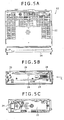
- FIG. 5A is a plan view of the apparatus body 12
- FIG. 5B is a front view of the apparatus body 12
- FIG. 5C is a view taken along arrow C of FIG. 5B .
- FIG. 6 illustrates the mounting of the microphone 20 onto the front panel 22.
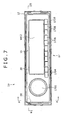
- FIG. 7 is a front view of the in-vehicle apparatus 10
- FIG. 8A is a sectional view taken along line A-A of FIG. 7
- FIG. 8B is an enlarged view of a major part of FIG. 8A
- FIG. 9 is a sectional view taken along line B-B of FIG. 7
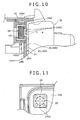
- FIG. 10 is an enlarged view of a major part of FIG. 9
- FIG. 11 is a view taken along arrow A of FIG. 10 , showing the condition where the lid 16 is removed from FIG. 9 .
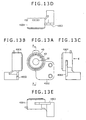
- FIG. 12 is a perspective view of a holder 40 onto which the microphone 20 and a cover 42 are mounted
- FIG. 13A is a plan view of the holder 40
- FIG. 13B is a view taken along arrow B of FIG. 13A
- FIG. 13C is a view taken along arrow C of FIG. 13A
- FIG. 13D is a view taken along arrow D of FIG. 13A
- FIG. 14 is a view taken along arrow E of FIG. 13C
- FIG. 15 is a sectional view taken along line A-A of FIG. 13A .
- the microphone 20 is provided in a location of the front surface 14 of the apparatus 12 so as to front on the front side of the front surface 14 in the condition where the lid 16 is opened.
- symbol 2002 in FIG. 6 denotes a wiring member for connection between the microphone 20 and the audio input unit 1008.
- a gap 34 for communication between a location, where the microphone 20 is provided, of the front surface 14 and the inside of the vehicle compartment 2 (the outside of the in-vehicle apparatus 10) is secured between the front surface 14 of the apparatus body 12 and the lid 16 in the condition where the front surface 14 is closed with the lid 16.
- the gap 34 extends between the front surface 14 of the apparatus body 12 and the lid 16 from a location, near the location where the microphone 20 is provided, of the outer periphery of the lid 16 to a location, fronting on the location where the microphone 20 is provided, of the back surface 30 of the lid 16, in the condition where the front surface 14 of the apparatus body 12 is closed with the lid 16.
- the gap 34 extends between the front surface part 1402 of the apparatus body 12 and the back surface part 3002 of the lid 16, from a position between a location, near the location where the microphone 20 is provided, of the side surface part 1404 of the apparatus body 12 and a location, fronting on the location of the side surface part 1404, of the side surface part 3004 of the lid 16 to the location where the microphone 20 is provided, in the condition where the front surface 14 of the apparatus body 12 is closed with the lid 16.
- the gap 34 extends as follows.
- the gap 34 extends with a substantially uniform value between the location, near the location where the microphone 20 is provided, of the side surface part 1404 of the apparatus body 12 and the location, fronting on the location of the side surface part 1404, of the side surface part 3004 of the lid 16, and extends with a substantially uniform value between the front surface part 1402 of the apparatus body 12 and the back surface part 3002 of the lid 16, to reach the microphone 20.
- a first gap 36 with a substantially uniform value is formed between the side surface part 1404 of the apparatus body 12 and the side surface part 3004 of the lid 16
- a second gap 38 with a substantially uniform value is formed between the front surface part 1402 of the apparatus body 12 and the back surface part 3002 of the lid 16.
- the gap 34 for communication between the location where the microphone 20 is provided and the inside of the vehicle compartment 2 (the outside of the in-vehicle apparatus 10) includes the first gap 36 and the second gap 38.
- the front surface 14 of the apparatus body 12 is rectangular in shape.
- the microphone 20 is provided at a location near an upper corner part of the rectangular shape of the front surface 14.
- the microphone 20 is disposed in the inside of the casing 22 so as to front on the inside surface 24B of the front panel 24, and a multiplicity of holes 2404 penetrating from the inside surface 24B to the outside surface 24A of the front panel 24 are provided in the location, fronting on the microphone 20, of the front panel 24.
- the microphone 20 is held by the holder 40 formed of a synthetic resin.
- the holder 40 has an attaching flange 4002 for attachment to the casing 22, and a tubular part 4004.
- the microphone 20 assumes a flat cylindrical shape, the outer peripheral part thereof is held by a cover 42 formed of a vibration-damping material, and the microphone 20 is mounted in the tubular part 4004 in the state of being covered with the cover 42.
- a sound pickup part of the microphone 20 is disposed toward the multiplicity of holes 2402.
- the lid 16 closing the front surface 14 of the apparatus body 10 is opened to open the loading/unloading gate 26, the disk-formed recording medium D is inserted, and the front surface 14 is closed with the lid 16. Then, the operating members 17 related to the reproduction are appropriately operated, to thereby perform the reproduction. Replacement of the disk-formed recording medium D is conducted by opening the lid 16.
- the operating members 17 related to the operation of the tuner unit 1004 are appropriately operated, for listening to the radio broadcasting.
- a Bluetooth radio line is established between the radiocommunication unit 9002 of the cellular phone 90 and the radiocommunication unit 1020 of the in-vehicle apparatus 10.
- the control unit 1014 controls the cellular phone 90 to establish a radio line between the cellular phone 90 and the telephone set 94 on the other end side of line, resulting in a condition where talking (conversation) can be made.
- an audio (voice) signal transmitted from the telephone set 94 on the other end side of line is supplied through the radiocommunication units 9002, 1020 and the control unit 1014 to the audio output unit 1006, and the voice from the other end side of line is outputted from the speaker 18, to be heard by the user.
- the voice of the user arrives at the microphone 20 to be picked up, since the gap 34 extends between the front surface 14 of the apparatus body 12 and the lid 16 from the location, near the location where the microphone 20 is provided, of the outer periphery of the lid 16 to the location, fronting on the location where the microphone 20 is provided, of the back surface 30 of the lid 16.
- the audio signal outputted from the microphone 20 is transmitted through the audio input unit 1008, the control unit 1014 and the radiocommunication units 1020, 9002 to the telephone set 94 on the other end side of line.
- a talk end switch 1709 is operated, whereby the radio line between the cellular phone 90 and the telephone set 94 is broken.
- the gap 34 for communication between the location where the microphone 20 is provided of the front surface 14 of the apparatus body 12 and the inside of the vehicle compartment 2 is secured between the front surface 14 and the lid 16 in the condition where the front surface 14 is closed with the lid 16. Therefore, notwithstanding the front surface 14 of the apparatus body 12 is closed with the lid 16, the user's voice can be propagated through the gap between the front surface 14 of the apparatus body 12 and the back surface 30 of the lid 16, to arrive at and be picked up by the microphone 20.
- the need for a wiring member for connection between the microphone and the in-vehicle apparatus is eliminated. Therefore, the installation space for such a wiring member can be reduced, and the installation of the in-vehicle apparatus can be simplified. Moreover, it is unnecessary for the outside surface 30 of the lid 16 where the in-vehicle apparatus 10 fronts on the inside of the vehicle compartment to be provided with holes or an opening for guiding sounds to the microphone 20, which is advantageous for enhancing the appearance quality and enhancing the degree of freedom in design.
- the gap 34 includes the first gap 36 having a uniform value and the second gap 38 having a uniform value, which is advantageous for obtaining an audio signal with good tone quality.
- the location where the microphone 20 is provided is a location near a corner part of the rectangular shape of the front surface 14 of the apparatus body 12, and this part is higher in rigidity than the parts, exclusive of the corner parts of the rectangular shape, of the front surface 14. Therefore, the microphone 20 is not liable to be influenced by vibration noises of the front surface 14 generated due to vibrations of the vehicle body, and pickup of unnecessary vibration sounds by the microphone 20 can be restrained, which is advantageous for picking up voices with good tone quality.
- the microphone 20 is provided at the lid 16, it would be necessary for the audio signal outputted from the microphone 20 to be transmitted to the audio input unit 1008 through the lid-side connector 33 and the apparatus body side connector 28, leading to the need for increasing the number of contact pieces of the lid-side connector 33 and the apparatus body side connector 28.
- the microphone 20 is provided in the apparatus body 12, so that the number of contact pieces of the lid-side connector 33 and the apparatus body side connector 28 can be reduced, which is advantageous for achieving reductions in the installation spaces and the parts costs of the lid-side connector 33 and the apparatus body side connector 28.
- the audio signal outputted from the microphone 20 is very weak.
- an amplification circuit for amplifying the audio signal outputted from the microphone 20 and a printed wiring board for constituting the amplification circuit are provided on the lid 16 side, and that the audio signal thus amplified is transmitted through a wiring member to the audio input unit 1008 provided in the apparatus body 12.
- the microphone 20 is provided in the apparatus body 12, so that there is no need to provide the lid 16 with an amplification circuit and a printed wiring board, which is more advantageous for reducing the installation spaces and the parts const of the amplification circuit and the printed wiring board.
- the wiring member for connection between the microphone 20 and the audio input unit 1008 can be shortened, which is advantageous for suppressing the influence of external noises on the audio signal and securing the tone quality of the audio signal.
- the lid 16 is provided with the printed wiring board, electromagnetic waves are shielded by the printed wiring board, so that it would be necessary to dispose the antenna 1021 of the radiocommunication unit 1020 at a location remote from the printed wiring board.
- the lid 16 is not provided with such a printed wiring board serving as a shield against electromagnetic waves, which is advantageous for securing the degree of freedom in laying out the antenna 1021.
- the antenna 1021 is disposed inside the apparatus body 12 at a position near the microphone 20; specifically, the antenna 1021 is disposed on the inside of the front panel 24 at a location in the vicinity of the inside surface 24B of the front panel 24.
- FIG. 16A is a diagram showing the frequency characteristic in the condition where the lid 16 is opened
- FIG. 16B is a diagram showing the frequency characteristic in the condition where the lid 16 is closed
- FIG. 16C is a diagram showing the frequency characteristic in the condition where the multiplicity of holes 2402 formed on the front side of the microphone 20 are shut tight.
- the axis of ordinates represents the level L (dB) of the audio signal outputted from the microphone 20, and the axis of abscissas represents the frequency f (Hz) of the voice.
- the level of the audio signal picked up by the microphone 20 after being guided through the gap 34 and the multiplicity of holes 2402 in the condition where the lid 16 is closed is not less than about -46 dB in a frequency range of 50 Hz to 2 kHz.
- the level of the audio signal of sound picked up by the microphone 20 after being transmitted through other portions of the casing 22 than the multiplicity of holes 2402 in the condition where the multiplicity of holes 2402 are closed is as extremely low as not more than -56 dB in a frequency range of 50 Hz to 2 kHz.
- the cellular phone 90 and the in-vehicle apparatus 10 are connected to each other by a Bluetooth or other radio line at the time of performing hands-free conversation has been described.
- the cellular phone 90 and the in-vehicle apparatus 10 are connected to each other by wiring.
- FIG. 27 is a block diagram showing the configuration of a control system in the in-vehicle apparatus 10 according to the second embodiment, in which the same or equivalent parts to those in the first embodiment above are denoted by the same symbols as used above.
- the hands-free conversation system includes a speaker 18, a microphone 20, an audio output unit 1006, an audio input unit 1008, an interface unit 1030, and a control unit 1014.
- the interface unit 1030 is provided in an apparatus body 12, and is for performing communication (conversation) by wire communication with an interface unit 9010 provided in the user's cellular phone 90.
- a connector 1032 connected to the interface unit 1030 is provided in the outside of the apparatus body 12, the cellular phone 90 is provided with a connector 9012 connected to the interface unit 9010, and the connectors 1032 and 9012 are connected to each other, to thereby enable the wire communication between the interface unit 1030 and the interface unit 9010.
- the wire communication an existing communication provided in the cellular phone 90 is used.
- control unit 1014 performs such a control that the audio signal transmitted from the telephone set 94 on the other end side through the public network 92 and the interface units 9010, 1030 is received, to be converted into voice by the audio output unit 1006 and the speaker 18, whereas the audio signal of the user's voice is transmitted through the microphone 20, the audio input unit 1008, the interface units 1030, 9010 and the public network 92 to the telephone set 94 on the other end side of line.
- the speaker 18 constitutes a part of the receiver unit for listening to the voice in the hands-free system
- the microphone 20 constitutes a part of the transmitter unit for picking up the voice in the hands-free system.
- the car audio system includes, for example, a semiconductor memory player for recording and/or reproduction of audio data or the like on a recording medium such as a memory card capable of being loaded in and unloaded from the apparatus body 12 or on a recording medium such as a semiconductor memory non-detachably incorporated in the apparatus body.
- the car audio system also includes an HDD player for recording and/or reproduction of audio data or the like on a hard disk drive, and a cassette tape player for recording and/or reproduction of audio data or the like on an audio cassette.
- the data recorded on a recording medium such as the disk-formed recording medium, the memory card, the semiconductor memory, etc. is not limited to audio data, and may be video data, for example.
- video data it suffices to provide the in-vehicle apparatus 10 with a display for displaying the reproduced video data.
- a recording medium with map data recorded thereon is inserted through a loading/unloading gate into the apparatus body, and the map data read from the recording medium is displayed on the display.
- the use of the microphone 20 is not limited to this use.
- the apparatus body 12 may be provided with a sound measuring unit for measuring or analyzing acoustic characteristics of the environment in which the apparatus body 12 is installed, based on the sound picked up by the microphone 20.
- a predetermined voice may be reproduced by the car audio system and, simultaneously, the voice in the vehicle compartment may be picked up by the microphone 20, then the acoustic characteristic thereof may be measured and/or analyzed by the sound measuring unit, and sound field calibration, for example, control of the volume and tone quality of the sound from each speaker, or the like may be automatically conducted based on the results of the measurement or analysis.
- the microphone 20 may function also as a part of the transmitter unit in the hands-free system, in the same manner as in the first and second embodiments.
Landscapes
- Engineering & Computer Science (AREA)
- Multimedia (AREA)
- Mechanical Engineering (AREA)
- Computer Networks & Wireless Communication (AREA)
- Signal Processing (AREA)
- Fittings On The Vehicle Exterior For Carrying Loads, And Devices For Holding Or Mounting Articles (AREA)
- Details Of Audible-Bandwidth Transducers (AREA)
Claims (18)
- Appareil embarqué dans un véhicule (10) comprenant :un corps d'appareil (12) ;une surface avant (14) dudit corps d'appareil (12) ; etun couvercle (16) configuré de façon à ouvrir et à fermer ladite surface avant (14) ;dans lequel un microphone (20), dirigé vers le côté avant de ladite surface avant (14) dans la condition dans laquelle ledit couvercle (16) est ouvert, est prévu au niveau de ladite surface avant (14) dudit corps d'appareil (12),caractérisé en ce queledit couvercle (16) comporte sur son côté avant (32) une unité d'actionnement (1010) adaptée de façon à actionner ledit appareil embarqué dans un véhicule (10), et une surface arrière (30) située en avant sur ladite surface avant (14) dudit corps d'appareil (12) dans la condition dans laquelle ledit couvercle (16) est fermé, dans lequeldans la condition dans laquelle le couvercle est fermé (16), un espace de communication (34, 36, 38) est prévu entre ladite surface avant (14) dudit corps d'appareil (12) et ledit couvercle (16), ledit espace (34, 36, 38) s'étendant depuis un pourtour extérieur dudit couvercle (16) jusqu'à ladite surface arrière (30) dudit couvercle (16) près de l'emplacement dans lequel ledit microphone (20) est prévu.
- Appareil embarqué dans un véhicule selon la revendication 1, dans lequel
ladite surface avant (14) dudit corps d'appareil (12) comprend une partie surface avant allongée horizontalement (1402) et une partie surface latérale (1404) s'élevant depuis le pourtour de ladite partie surface avant (1402) ;
ladite surface arrière (30) dudit couvercle (16) a une partie surface arrière (3002) située en avant sur ladite partie surface avant (1402), et une partie surface latérale (3004) s'élevant depuis le pourtour de ladite partie surface arrière (3002) et située en avant sur ladite partie surface latérale (1404) de ladite surface avant (14), dans l'état de fermeture de ladite surface avant (14) dudit corps d'appareil (12) ; et
ledit espace (34, 36, 38) s'étend entre ladite partie surface avant (1402) dudit corps d'appareil (12) et ladite partie surface arrière (3002) dudit couvercle (16) depuis une position entre un emplacement, près dudit emplacement dans lequel ledit microphone (20) est prévu, de ladite partie surface latérale (1404) dudit corps d'appareil (12) et un emplacement, situé en avant dudit emplacement de ladite partie surface latérale (1404) dudit corps d'appareil (12), de ladite partie surface latérale (3004) dudit couvercle (16), jusqu'audit emplacement dans lequel ledit microphone (20) est prévu, dans la condition dans laquelle ladite surface avant (14) dudit corps d'appareil (12) est fermée avec ledit couvercle (16). - Appareil embarqué dans un véhicule selon la revendication 1, dans lequel
ladite surface avant (14) dudit corps d'appareil comprend une partie surface avant allongée horizontalement (1402) et une partie surface latérale (1404) s'élevant depuis le pourtour de ladite partie surface avant (1402) ;
ladite surface arrière (30) dudit couvercle (16) a une partie surface arrière (3002) située en avant sur ladite partie surface avant (1402), et une partie surface latérale (3004) s'élevant depuis le pourtour de ladite partie surface arrière (3002) et située en avant sur ladite partie surface latérale (1404) de ladite surface avant (14), dans la condition dans laquelle ladite surface avant (14) est fermée ; et
ledit espace (34, 36, 38) s'étend avec une valeur essentiellement uniforme entre un emplacement, près dudit emplacement dans lequel ledit microphone (20) est prévu, de ladite partie surface latérale (1404) dudit corps d'appareil (12) et un emplacement, situé en avant dudit emplacement de ladite surface latérale, de ladite partie surface latérale (3004) dudit couvercle, et s'étend avec une valeur essentiellement uniforme entre ladite partie surface avant (1402) dudit corps d'appareil (12) et ladite partie surface arrière (3002) dudit couvercle (16), jusqu'à atteindre ledit emplacement dans lequel ledit microphone (20) est prévu. - Appareil embarqué dans un véhicule selon la revendication 1, dans lequel
ladite surface avant (14) dudit corps d'appareil (12) comprend une partie surface avant allongée horizontalement (1402) et une partie surface latérale (1404) s'élevant depuis le pourtour de ladite partie surface avant (1402) ;
ladite surface arrière (30) dudit couvercle (16) a une partie surface arrière (3002) située en avant sur ladite partie surface avant (1402), et une partie surface latérale (3004) s'élevant depuis le pourtour de ladite partie surface arrière (3002) et située en avant sur ladite partie surface latérale (1404) de ladite surface avant (14), dans la condition dans laquelle ladite surface avant (14) est fermée ;
un premier espace (36) avec une valeur essentiellement uniforme est formé entre ladite partie surface latérale (1404) dudit corps d'appareil (12) et ladite partie surface latérale (3004) dudit couvercle (16), et un deuxième espace (38) avec une valeur essentiellement uniforme est formé entre ladite partie surface avant (1402) dudit corps d'appareil (12) et ladite partie surface arrière (3002) dudit couvercle (16), dans la condition dans laquelle ladite surface avant (14) dudit corps d'appareil (12) est fermée avec ledit couvercle (16) ; et
ledit espace (34) pour la communication entre ledit emplacement dans lequel ledit microphone (20) est prévu et l'extérieur est composé de façon à comprendre ledit premier espace (36) et ledit deuxième espace (38), dans la condition dans laquelle ladite surface avant (14) dudit corps d'appareil (12) est fermée avec ledit couvercle (16). - Appareil embarqué dans un véhicule selon la revendication 1, dans lequel
ladite surface avant (14) dudit corps d'appareil (12) a une forme essentiellement rectangulaire ; et
ledit microphone (20) est prévu dans un emplacement près d'une partie coin de ladite forme rectangulaire de ladite surface avant (14). - Appareil embarqué dans un véhicule selon la revendication 1, dans lequel
ledit corps d'appareil (12) a un boîtier, ladite partie avant dudit corps d'appareil (12) est une surface extérieure d'un panneau avant constituant une surface avant dudit boîtier,
ledit panneau avant a une surface intérieure située en avant sur l'intérieur dudit boîtier,
ledit microphone (20) est disposé dans l'intérieur dudit boîtier de façon à être situé en avant sur ladite surface intérieure dudit panneau avant, et
une pluralité de trous (2402) pénétrant depuis la surface intérieure jusqu'à la surface extérieure dudit panneau avant sont prévus dans ledit panneau avant à un emplacement situé en avant dudit microphone (20). - Appareil embarqué dans un véhicule selon la revendication 6, dans lequel
ledit microphone (20) est maintenu par un couvercle (40, 42) formé en utilisant un matériau d'amortissement de vibrations, et il est monté en position à travers ledit couvercle. - Appareil embarqué dans un véhicule selon la revendication 1, dans lequel
ladite unité d'actionnement (1010) comporte une pluralité d'éléments d'actionnement (1702, 1704, 1706, 1708, 1709) pour actionner ledit appareil embarqué dans un véhicule, lesdits éléments d'actionnement (1702, 1704, 1706, 1708, 1709) étant disposés au niveau de ladite surface avant (32) dudit couvercle (16) où ledit couvercle est situé en avant sur l'extérieur dans la condition dans laquelle ladite surface avant (14) dudit corps d'appareil (12) est fermée avec ledit couvercle (16). - Appareil embarqué dans un véhicule selon la revendication 1, dans lequel
ledit couvercle (16) est prévu de façon à pouvoir être pivoté par rapport à ladite surface avant (14) dudit corps d'appareil (12) ;
un connecteur (33) pour la connexion à ladite unité d'actionnement (1010) est prévu au niveau de ladite surface arrière (30) dudit couvercle (16) ; et
un connecteur (28), qui est engagé avec ledit connecteur (33) au niveau de ladite surface arrière (30) dudit couvercle (16) dans la condition dans laquelle ladite surface avant (14) dudit corps d'appareil (12) est fermée avec ledit couvercle (16) et qui est dégagé dudit connecteur (33) au niveau de ladite surface arrière dudit couvercle (16) dans la condition dans laquelle ladite surface avant (14) dudit corps d'appareil (12) est ouverte, est prévu au niveau de ladite surface avant (14) dudit corps d'appareil (12). - Appareil embarqué dans un véhicule selon la revendication 1, dans lequel
ledit couvercle (16) est prévu de façon à pouvoir être pivoté par rapport à ladite surface avant (14) dudit corps d'appareil (12). - Appareil embarqué dans un véhicule selon la revendication 1, dans lequel
ledit couvercle (16) est prévu de façon à être détachable de ladite surface avant (14) dudit corps d'appareil (12). - Appareil embarqué dans un véhicule selon la revendication 1, dans lequel
ledit corps d'appareil (12) a un cadre de couvercle (1430, 1432) pour supporter de manière détachable ledit couvercle (16) et pour bouger ledit couvercle dans les directions d'ouverture et de fermeture de ladite surface avant (14) dudit corps d'appareil (12) ;
un substrat flexible (96) pour le transfert de signaux entre ladite unité d'actionnement (1010) au niveau dudit couvercle (16) supporté par ledit cadre (1430, 1432) et ledit corps d'appareil (12) est prévu entre ledit cadre et ledit corps d'appareil ; et
un connecteur pour le transfert de signaux entre ladite unité d'actionnement (1010) et ledit corps d'appareil à travers ledit substrat flexible (96) est attaché de manière détachable audit couvercle et audit cadre. - Appareil embarqué dans un véhicule selon la revendication 1, dans lequel
ledit corps d'appareil (12) est pourvu d'une unité de reproduction (1002) pour la reproduction de données enregistrées sur un support d'enregistrement, et ladite surface avant (14) dudit corps d'appareil (12) est pourvue d'une fente d'insertion/d'extraction (26) pour insérer et retirer ledit support d'enregistrement. - Appareil embarqué dans un véhicule selon la revendication 1, dans lequel
ledit corps d'appareil (12) est pourvu d'une unité de reproduction (1002) pour reproduire des données audio enregistrées sur un support d'enregistrement sous forme de disque et pour fournir un signal audio, et une unité de sortie audio (1006) pour appliquer un traitement de signal prédéterminé audit signal audio sorti de ladite unité de reproduction (1002) et pour alimenter un signal traité à un haut-parleur (18) ;
ladite surface avant dudit corps d'appareil est pourvue d'une fente d'insertion/d'extraction (26) pour insérer et retirer ledit support d'enregistrement sous forme de disque ; et
ladite unité de reproduction (1002) et ladite unité de sortie audio (1006) constituent une partie d'un système audio de voiture. - Appareil embarqué dans un véhicule selon la revendication 1, dans lequel
ledit corps d'appareil est pourvu d'une unité de reproduction (1002) pour reproduire des données audio enregistrées sur un support d'enregistrement sous forme de disque et pour fournir un signal audio, et d'une unité de sortie audio (1006) pour appliquer un traitement de signal prédéterminé audit signal audio sorti de ladite unité de reproduction et pour alimenter un signal traité à un haut-parleur ;
ladite surface avant dudit corps d'appareil est pourvue d'une fente d'insertion/d'extraction (26) pour insérer et retirer ledit support d'enregistrement sous forme de disque ;
ladite unité de reproduction (1002) et ladite unité de sortie audio (1006) constituent une partie d'un système audio de voiture ; et
ladite unité d'actionnement (1010) est configurée de façon à actionner ledit système audio de voiture. - Appareil embarqué dans un véhicule selon la revendication 1, dans lequel
ledit corps d'appareil est pourvu d'un système mains libres configuré de façon à ce qu'une conversation mains libres puisse avoir lieu au moyen d'un téléphone cellulaire (90), et ledit microphone (20) a au moins la fonction de capter le son dans ledit système mains libres. - Appareil embarqué dans un véhicule selon la revendication 1, dans lequel
ledit corps d'appareil est pourvu d'une unité de mesure du son (1008) pour mesurer ou analyser les caractéristiques acoustiques dans l'environnement dans lequel ledit corps d'appareil (12) est disposé, en se basant sur un son capté,
lesdites caractéristiques acoustiques mesurées ou analysées sont utilisées pour calibrer le champ acoustique dans ledit environnement, et
ledit microphone a au moins la fonction de capter ledit son. - Appareil embarqué dans un véhicule selon la revendication 1, dans lequel
ledit corps d'appareil (12) est disposé dans un compartiment de véhicule (2) et ladite surface avant (14) dudit corps d'appareil (12) est située en avant sur ledit compartiment du véhicule (2) dans la condition dans laquelle ledit couvercle (16) est ouvert.
Applications Claiming Priority (1)
| Application Number | Priority Date | Filing Date | Title |
|---|---|---|---|
| JP2006040495A JP4406843B2 (ja) | 2006-02-17 | 2006-02-17 | 車載機器 |
Publications (3)
| Publication Number | Publication Date |
|---|---|
| EP1820698A2 EP1820698A2 (fr) | 2007-08-22 |
| EP1820698A3 EP1820698A3 (fr) | 2012-05-23 |
| EP1820698B1 true EP1820698B1 (fr) | 2013-11-06 |
Family
ID=38055650
Family Applications (1)
| Application Number | Title | Priority Date | Filing Date |
|---|---|---|---|
| EP07003357.6A Expired - Fee Related EP1820698B1 (fr) | 2006-02-17 | 2007-02-16 | Appareil embarqué |
Country Status (4)
| Country | Link |
|---|---|
| US (1) | US7689255B2 (fr) |
| EP (1) | EP1820698B1 (fr) |
| JP (1) | JP4406843B2 (fr) |
| CN (1) | CN101026845B (fr) |
Families Citing this family (14)
| Publication number | Priority date | Publication date | Assignee | Title |
|---|---|---|---|---|
| US8190214B2 (en) * | 2008-02-19 | 2012-05-29 | Denso Corporation | In-vehicle handsfree apparatus |
| US9026184B2 (en) * | 2008-02-19 | 2015-05-05 | Denso Corporation | In-vehicle handsfree apparatus |
| US8155709B2 (en) * | 2008-02-19 | 2012-04-10 | Denso Corporation | In-vehicle handsfree apparatus |
| US8019391B2 (en) * | 2008-02-19 | 2011-09-13 | Denso Corporation | In-vehicle handsfree apparatus |
| JP4971220B2 (ja) * | 2008-02-29 | 2012-07-11 | 小島プレス工業株式会社 | 車載用マイク装置 |
| US8174577B2 (en) * | 2008-09-11 | 2012-05-08 | Tech-Cast Mfg. Corp. | Automatic in-car video recording apparatus for recording driving conditions inside and outside a car |
| DE102009029367B4 (de) * | 2009-09-11 | 2012-01-12 | Dietmar Ruwisch | Verfahren und Vorrichtung zur Analyse und Abstimmung akustischer Eigenschaften einer Kfz-Freisprecheinrichtung |
| FR2969966B1 (fr) * | 2011-01-04 | 2013-07-26 | Parrot | Architecture d'equipement multimedia et de telephonie mains-libres pour vehicule automobile. |
| KR101066212B1 (ko) | 2011-03-10 | 2011-09-20 | 한국뉴매틱(주) | 퀵-릴리즈 진공펌프 |
| US9406310B2 (en) * | 2012-01-06 | 2016-08-02 | Nissan North America, Inc. | Vehicle voice interface system calibration method |
| JP5673603B2 (ja) * | 2012-05-28 | 2015-02-18 | 株式会社デンソー | スイッチ構造 |
| US9228836B2 (en) * | 2013-03-15 | 2016-01-05 | Cambridge Mobile Telematics | Inference of vehicular trajectory characteristics with personal mobile devices |
| KR101638611B1 (ko) * | 2014-12-16 | 2016-07-11 | 현대자동차주식회사 | 블루투스 스트리밍 최적화 시스템 및 그 방법 |
| JP7139272B2 (ja) * | 2019-03-20 | 2022-09-20 | 株式会社トランストロン | 車載装置 |
Family Cites Families (16)
| Publication number | Priority date | Publication date | Assignee | Title |
|---|---|---|---|---|
| US4924193A (en) * | 1987-01-30 | 1990-05-08 | Nec Corporation | Volume control circuit for use in portable telephone or the like |
| JPH05131881A (ja) * | 1991-11-13 | 1993-05-28 | Honda Access:Kk | 自動車用無線電話装置 |
| JP2626534B2 (ja) | 1993-12-28 | 1997-07-02 | 日本電気株式会社 | 電子機器の送話部構造 |
| JPH0983623A (ja) | 1995-09-11 | 1997-03-28 | Oki Electric Ind Co Ltd | 接話型マイクロホンの取付構造 |
| JPH09233164A (ja) | 1996-02-21 | 1997-09-05 | Hitachi Ltd | 携帯無線端末機 |
| US6420975B1 (en) * | 1999-08-25 | 2002-07-16 | Donnelly Corporation | Interior rearview mirror sound processing system |
| JP3339475B2 (ja) | 1999-09-28 | 2002-10-28 | 株式会社デンソー | 無線通信端末の着信制御装置 |
| US6980092B2 (en) * | 2000-04-06 | 2005-12-27 | Gentex Corporation | Vehicle rearview mirror assembly incorporating a communication system |
| CN2448032Y (zh) * | 2000-09-08 | 2001-09-12 | 葛清华 | 自动切换麦克风的免持听筒麦克风装置 |
| US7020499B2 (en) * | 2001-12-07 | 2006-03-28 | Bellsouth Intellectual Property Corporation | Hands free vehicle mounted mobile telephone with audio |
| CN2563859Y (zh) * | 2002-08-02 | 2003-07-30 | 黄国俊 | 设于汽车上的行动电话免持听筒装置 |
| US6993367B2 (en) * | 2002-09-04 | 2006-01-31 | Fujitsu Ten Limited | In-car telephone system, hands-free unit and portable telephone unit |
| US20050096099A1 (en) * | 2003-11-04 | 2005-05-05 | Barclay Deborah L. | Integrated hands free mobile system |
| DE202004009568U1 (de) * | 2004-06-17 | 2004-10-28 | Trw Automotive Safety Systems Gmbh | Fahrzeuglenkrad |
| ATE430424T1 (de) * | 2004-11-02 | 2009-05-15 | Harman Becker Automotive Sys | Versorgung eines fahrzeugaudiosystems mit in einem mobilen audiogerät gespeicherten audiodaten |
| JP4506604B2 (ja) * | 2005-07-27 | 2010-07-21 | 株式会社デンソー | ハンズフリー装置 |
-
2006
- 2006-02-17 JP JP2006040495A patent/JP4406843B2/ja not_active Expired - Fee Related
-
2007
- 2007-02-16 CN CN2007100789313A patent/CN101026845B/zh not_active Expired - Fee Related
- 2007-02-16 EP EP07003357.6A patent/EP1820698B1/fr not_active Expired - Fee Related
- 2007-02-16 US US11/706,961 patent/US7689255B2/en not_active Expired - Fee Related
Also Published As
| Publication number | Publication date |
|---|---|
| JP4406843B2 (ja) | 2010-02-03 |
| EP1820698A3 (fr) | 2012-05-23 |
| US7689255B2 (en) | 2010-03-30 |
| US20070207840A1 (en) | 2007-09-06 |
| EP1820698A2 (fr) | 2007-08-22 |
| CN101026845B (zh) | 2010-12-29 |
| CN101026845A (zh) | 2007-08-29 |
| JP2007216856A (ja) | 2007-08-30 |
Similar Documents
| Publication | Publication Date | Title |
|---|---|---|
| EP1820698B1 (fr) | Appareil embarqué | |
| US7668576B2 (en) | Incorporating a portable digital music player into a vehicle audio system | |
| KR101442237B1 (ko) | 차량―장착식 오디오 장치 및 자동차 | |
| EP0693237B1 (fr) | Dispositif de communication vocale en direct pour telephones cellulaires utilisable notamment en association avec un poste recepteur radio de vehicule automobile | |
| JPH04271939A (ja) | 放送ラジオ受信機と無線電話とを組み合わせた無線装置 | |
| US8154858B2 (en) | Electronic device and electronic system | |
| WO2009125611A1 (fr) | Dispositif électronique | |
| US20070215407A1 (en) | Loudspeaker device | |
| JPS58191647A (ja) | カ−ラジオ | |
| US7885057B2 (en) | Electronic device and electronic system | |
| JP2009027479A (ja) | 電力線通信音響再生装置 | |
| EP1802162A1 (fr) | Microphone pour appareil électronique | |
| JPWO2005125268A1 (ja) | スピーカ付き電子機器 | |
| EP1939884B1 (fr) | Appareil acoustique embarqué | |
| CN101297538B (zh) | 具有用于无线设备的对讲装置的驾驶员信息系统 | |
| KR100440924B1 (ko) | 차량용 핸즈프리 장치 | |
| WO2005090126A1 (fr) | Systeme d'interface de dispositif audio | |
| CN121608694A (zh) | 可拆卸的车载音频播放系统 | |
| WO2009125629A1 (fr) | Dispositif électronique | |
| JPS63153785A (ja) | 記録媒体演奏装置 | |
| KR20080048912A (ko) | 차량용 멀티미디어 랙장치 | |
| JPH0729981U (ja) | 携帯電話機用車載アダプタ | |
| JPH08124370A (ja) | 携帯用電子機器 |
Legal Events
| Date | Code | Title | Description |
|---|---|---|---|
| PUAI | Public reference made under article 153(3) epc to a published international application that has entered the european phase |
Free format text: ORIGINAL CODE: 0009012 |
|
| AK | Designated contracting states |
Kind code of ref document: A2 Designated state(s): AT BE BG CH CY CZ DE DK EE ES FI FR GB GR HU IE IS IT LI LT LU LV MC NL PL PT RO SE SI SK TR |
|
| AX | Request for extension of the european patent |
Extension state: AL BA HR MK YU |
|
| RIC1 | Information provided on ipc code assigned before grant |
Ipc: G11B 33/02 20060101ALI20111229BHEP Ipc: G11B 31/00 20060101ALI20111229BHEP Ipc: H04M 1/60 20060101ALI20111229BHEP Ipc: B60R 11/02 20060101AFI20111229BHEP |
|
| PUAL | Search report despatched |
Free format text: ORIGINAL CODE: 0009013 |
|
| AK | Designated contracting states |
Kind code of ref document: A3 Designated state(s): AT BE BG CH CY CZ DE DK EE ES FI FR GB GR HU IE IS IT LI LT LU LV MC NL PL PT RO SE SI SK TR |
|
| AX | Request for extension of the european patent |
Extension state: AL BA HR MK RS |
|
| RIC1 | Information provided on ipc code assigned before grant |
Ipc: G11B 33/02 20060101ALI20120418BHEP Ipc: G11B 31/00 20060101ALI20120418BHEP Ipc: H04M 1/60 20060101ALI20120418BHEP Ipc: B60R 11/02 20060101AFI20120418BHEP |
|
| 17P | Request for examination filed |
Effective date: 20121116 |
|
| AKX | Designation fees paid |
Designated state(s): DE FR GB |
|
| 17Q | First examination report despatched |
Effective date: 20130222 |
|
| GRAP | Despatch of communication of intention to grant a patent |
Free format text: ORIGINAL CODE: EPIDOSNIGR1 |
|
| INTG | Intention to grant announced |
Effective date: 20130603 |
|
| GRAS | Grant fee paid |
Free format text: ORIGINAL CODE: EPIDOSNIGR3 |
|
| GRAA | (expected) grant |
Free format text: ORIGINAL CODE: 0009210 |
|
| AK | Designated contracting states |
Kind code of ref document: B1 Designated state(s): DE FR GB |
|
| REG | Reference to a national code |
Ref country code: GB Ref legal event code: FG4D |
|
| REG | Reference to a national code |
Ref country code: DE Ref legal event code: R096 Ref document number: 602007033600 Country of ref document: DE Effective date: 20140102 |
|
| PGFP | Annual fee paid to national office [announced via postgrant information from national office to epo] |
Ref country code: DE Payment date: 20140219 Year of fee payment: 8 |
|
| PGFP | Annual fee paid to national office [announced via postgrant information from national office to epo] |
Ref country code: FR Payment date: 20140219 Year of fee payment: 8 |
|
| PGFP | Annual fee paid to national office [announced via postgrant information from national office to epo] |
Ref country code: GB Payment date: 20140218 Year of fee payment: 8 |
|
| REG | Reference to a national code |
Ref country code: DE Ref legal event code: R097 Ref document number: 602007033600 Country of ref document: DE |
|
| PLBE | No opposition filed within time limit |
Free format text: ORIGINAL CODE: 0009261 |
|
| STAA | Information on the status of an ep patent application or granted ep patent |
Free format text: STATUS: NO OPPOSITION FILED WITHIN TIME LIMIT |
|
| 26N | No opposition filed |
Effective date: 20140807 |
|
| REG | Reference to a national code |
Ref country code: DE Ref legal event code: R097 Ref document number: 602007033600 Country of ref document: DE Effective date: 20140807 |
|
| REG | Reference to a national code |
Ref country code: DE Ref legal event code: R119 Ref document number: 602007033600 Country of ref document: DE |
|
| GBPC | Gb: european patent ceased through non-payment of renewal fee |
Effective date: 20150216 |
|
| REG | Reference to a national code |
Ref country code: FR Ref legal event code: ST Effective date: 20151030 |
|
| PG25 | Lapsed in a contracting state [announced via postgrant information from national office to epo] |
Ref country code: DE Free format text: LAPSE BECAUSE OF NON-PAYMENT OF DUE FEES Effective date: 20150901 Ref country code: GB Free format text: LAPSE BECAUSE OF NON-PAYMENT OF DUE FEES Effective date: 20150216 |
|
| PG25 | Lapsed in a contracting state [announced via postgrant information from national office to epo] |
Ref country code: FR Free format text: LAPSE BECAUSE OF NON-PAYMENT OF DUE FEES Effective date: 20150302 |