EP1820708B1 - Agencement hydraulique - Google Patents
Agencement hydraulique Download PDFInfo
- Publication number
- EP1820708B1 EP1820708B1 EP07102574A EP07102574A EP1820708B1 EP 1820708 B1 EP1820708 B1 EP 1820708B1 EP 07102574 A EP07102574 A EP 07102574A EP 07102574 A EP07102574 A EP 07102574A EP 1820708 B1 EP1820708 B1 EP 1820708B1
- Authority
- EP
- European Patent Office
- Prior art keywords
- pressure
- control
- trailer
- hydraulic
- line
- Prior art date
- Legal status (The legal status is an assumption and is not a legal conclusion. Google has not performed a legal analysis and makes no representation as to the accuracy of the status listed.)
- Active
Links
Images




Classifications
-
- B—PERFORMING OPERATIONS; TRANSPORTING
- B60—VEHICLES IN GENERAL
- B60T—VEHICLE BRAKE CONTROL SYSTEMS OR PARTS THEREOF; BRAKE CONTROL SYSTEMS OR PARTS THEREOF, IN GENERAL; ARRANGEMENT OF BRAKING ELEMENTS ON VEHICLES IN GENERAL; PORTABLE DEVICES FOR PREVENTING UNWANTED MOVEMENT OF VEHICLES; VEHICLE MODIFICATIONS TO FACILITATE COOLING OF BRAKES
- B60T7/00—Brake-action initiating means
- B60T7/12—Brake-action initiating means for automatic initiation; for initiation not subject to will of driver or passenger
- B60T7/20—Brake-action initiating means for automatic initiation; for initiation not subject to will of driver or passenger specially for trailers, e.g. in case of uncoupling of or overrunning by trailer
-
- B—PERFORMING OPERATIONS; TRANSPORTING
- B60—VEHICLES IN GENERAL
- B60T—VEHICLE BRAKE CONTROL SYSTEMS OR PARTS THEREOF; BRAKE CONTROL SYSTEMS OR PARTS THEREOF, IN GENERAL; ARRANGEMENT OF BRAKING ELEMENTS ON VEHICLES IN GENERAL; PORTABLE DEVICES FOR PREVENTING UNWANTED MOVEMENT OF VEHICLES; VEHICLE MODIFICATIONS TO FACILITATE COOLING OF BRAKES
- B60T11/00—Transmitting braking action from initiating means to ultimate brake actuator without power assistance or drive or where such assistance or drive is irrelevant
- B60T11/10—Transmitting braking action from initiating means to ultimate brake actuator without power assistance or drive or where such assistance or drive is irrelevant transmitting by fluid means, e.g. hydraulic
- B60T11/108—Transmitting braking action from initiating means to ultimate brake actuator without power assistance or drive or where such assistance or drive is irrelevant transmitting by fluid means, e.g. hydraulic to a trailer fluid system
Definitions
- the invention relates to a hydraulic arrangement for braking a trailer, with a hydraulically connectable to a brake system of a trailer brake line, a hydraulic source, a hydraulic tank, a hydraulic source and the tank with the brake line connecting, hydraulically controllable trailer brake valve, a between the brake line and the Trailer brake valve extending first control pressure line, a extending between the trailer brake valve and a control pressure source second control pressure line and arranged in the second control pressure line, adjustable, pressure reducing means for controlling the control pressure.
- the object underlying the invention is seen to provide a hydraulic arrangement of the type mentioned, by which the aforementioned problems are overcome.
- a hydraulic arrangement of the aforementioned type comprises a control pressure source, which is formed as part of the hydraulic circuit of a brake system of a towing vehicle pulling the trailer, wherein the pressure reducing means by an adjustable biasing force mechanically in an open basic position is zwingbar.
- the control pressure source is formed as part of the hydraulic circuit of the brake system of the towing vehicle
- a control pressure in the second control pressure line can be generated by generating a brake pressure in the towing vehicle, for example by pressing the brake pedal.
- the pressure reducing means is in an open basic position, so that even if an electronic control fails on the towing vehicle, the functionality of the hydraulic brake system for the trailer is guaranteed.
- the control pressure source can be designed, for example, as a hydraulic line connected to the brake system of the towing vehicle.
- the second control pressure line can be branched off directly from the brake line, so that whenever a pressure is built up in the brake line of the towing vehicle, a control pressure is present for controlling the trailer brake valve.
- the control pressure line can be branched off directly or indirectly, for example via a connecting part or a valve, to be connected to the brake line or another brake pressure or a pressure line leading the brake system of the towing vehicle.
- the pressure reducing means in the second control pressure line is designed as an adjustable, hydraulically switchable pressure reducing valve.
- the pressure reducing valve is designed such that the biasing force is adjustable or adjustable by an operator, be it by manual, electric or hydraulic means, whereby it is always ensured that a pre-set biasing force acts independently of hydraulic or electrical means.
- the pressure reducing valve Via a pilot pressure line leading from the second control pressure line trailer brake valve side to the pressure reducing valve, the pressure reducing valve can be brought into a closed position, provided that the pressure prevailing in the control pressure line overcomes the preset biasing force. Should therefore set in the second control pressure line, a control pressure that exceeds the preset value, the pressure reducing valve is brought into the closed position.
- the trailer brake valve is variably driven up to a preset pressure for the second control pressure line according to the pressure generated by the brake system for the towing vehicle or the pressure generated by the control pressure source.
- a bypass line which is connected in parallel to the pressure reducing valve allows the arrangement of a check valve, which is closed in the direction of the trailer brake valve and by which a return flow of hydraulic fluid from the second control pressure line is simplified or accelerated.
- the pressure reducing valve may be formed as a conventional pressure reducing valve, which closes the second control pressure line from a certain control pressure in the second control pressure line, or as a switching valve which closes the second control pressure line in both directions or at least in the direction of the trailer brake valve from a certain pressure in the brake line.
- this is connected via a pilot pressure line to the brake line of the trailer, so that, when a maximum brake pressure, the switching valve closes hydraulically closes.
- the pressure reducing valve preferably has an adjustable biasing spring, with which the biasing force is generated, which forces the pressure reducing valve in an open basic position.
- the biasing spring can be manually or electrically adjusted by an operator.
- the biasing force of the adjusting spring is given purely mechanically, at which maximum pressure the Pressure reducing valve should close, so that even if one of the braking system of the trailer or the towing vehicle or components of these controlling electronics, a braking the trailer and the brake system of the towing vehicle branched brake pressure is built up.
- Adjusting the preload spring sets a maximum brake pressure for the trailer.
- the control pressure in the control pressure line, which controls the trailer brake valve can be set to a specific maximum pressure which, in accordance with the previously mentioned guidelines, for example 100 bar (120 bar in France), must not fall below 150 bar.
- the pressure reducing valve may comprise electronic adjusting means which make it possible to generate a force which counteracts or enhances the biasing force of the biasing spring.
- Such electronic adjusting means may be formed, for example, as magnetic coils, which influence a deflection of the biasing spring, ie increase or decrease.
- the preload spring must be set so strong that in case of failure of an electrical system, the rules mentioned above are still met.
- the max. Trailer brake pressure not less than 100 bar (120 bar in France) and not exceeding 150 bar. If the spring is set to 100 bar (120 bar in France), with increasing electrical control signal, a higher hydraulic pressure can be built to switch the pressure reducing valve, which, as mentioned above, can be designed as a pressure reducing valve or as a switching valve.
- the preload spring can be electronically amplified by up to 50 bar. If the spring is set to 150 bar, must with increasing electronic control signal, a lower hydraulic pressure are built to switch the pressure reducing valve. The preload spring can be relieved electronically by up to 50 bar in this case. In the event of a failure of the electrical system, the trailer would still be able to be braked, the maximum pressure being either 100 bar (120 bar in France) or 150 bar. Even with the use of switching valves in place of pressure reducing valves as pressure reducing valves, electronic adjustments or controls of the biasing spring can be applied so that the same electronic means amplifying or relieving, in case of failure of the electrical system, the trailer with max. 100 bar or 150 bar to brake. In this case, it is not the control pressure acting in the second control pressure line which is decisive, but the pressure acting in the brake line for the trailer, as described above.
- the trailer brake valve may be formed as a proportional slide valve, which is hydraulically actuated via the first control pressure line from the brake line of the trailer and hydraulically via the second control pressure line from the brake system of the towing vehicle.
- the trailer brake valve is designed so that with increasing control pressure in the second control pressure line, the slide shifts proportionally or increasingly opens, so that sets a higher brake pressure by the funded by the hydraulic source hydraulic fluid. In this case, at maximum brake pressure for the trailer equilibrium, since the pressure on the part of the brake line in the first control pressure line counteracts the pressure in the second control pressure line.
- a third control pressure line may be provided, with which the trailer brake valve is hydraulically controllable in addition to the first and second control pressure line.
- the third control pressure line is preferably provided with an electronically adjustable pressure reducing valve which connects the hydraulic source and the hydraulic tank with the third control pressure line.
- the additional control of the trailer brake valve can be used to a map change of the trailer brake valve, so that by applying an additional control pressure, the braking behavior of the trailer can be made flexible.
- the arrangement of the third control pressure line is preferably carried out parallel to the second control pressure line. The essence of this embodiment is further the limitation of the maximum trailer brake pressure by the maximum control pressure in the second control pressure line to a value of 100 bar or 120 bar, as previously explained.
- the limiting pressure can be fixed and not electronically adjustable, except for the difference of 100 bar and 120 bar.
- the braking behavior or the behavior of the slide valve is thereby designed so that the vehicle and its trailer can be braked in its most unfavorable condition with regard to the French regulation.
- This basic setting of the Control signal by the control pressure in the second control pressure line to the trailer brake valve spool is now superimposed by the control pressure of the third control pressure line, which is adjusted by the arranged between the third control pressure line and the hydraulic source or hydraulic tank elektroproportionalale pressure reducing valve. Due to the additional third control pressure, the slide valve can be deflected to a greater extent and thus a greater braking effect can be achieved. It thus takes place a superposition of the two pressures and it is possible to change the map of the trailer brake valve freely within predetermined limits and so to set the braking behavior of the entire train positive with respect to the driving behavior.
- a pressure sensor is provided, with which the pressure of the brake system of the towing vehicle can be determined. The measured by the pressure sensor pressure in the brake system of the towing vehicle can then be used for further processing and optimization of the hydraulic arrangement.
- An electronic control unit for controlling or regulating electronically adjustable or switchable valves and for processing electronic sensor signals evaluates the pressure measured in the brake system of the towing vehicle by the pressure sensor or pressure sensors and calculates the pressure reduction valve in accordance with the characteristic curve for the trailer brake valve specified by the operator the third control pressure line to be generated control pressure, which then deflects the trailer brake valve spool further than would be possible only by the control pressure generated in the second control pressure line by the brake signal of the towing vehicle of the towing vehicle.
- the control pressures in the second and third control pressure line there is a superposition of the control pressures in the second and third control pressure line. It is thus possible to change the map of the trailer brake valve freely within predetermined limits and so to set the braking behavior of the entire train positive with respect to the driving behavior.
- a hydraulic arrangement according to the invention is particularly suitable for a combination of trailer and towing vehicle in agricultural operation, wherein a hydraulic brake system for the trailer and a hydraulic brake system is provided for the towing vehicle.
- a hydraulic brake system for the trailer and a hydraulic brake system is provided for the towing vehicle.
- other applications are conceivable in which a combination of towing vehicle and trailer with hydraulic brake systems are used and a hydraulic arrangement according to the invention can be used, for example in the field of commercial vehicles or even in the field of passenger cars.
- the advantages of the invention are in particular that it is possible for an operator to consider the state of charge of his trailer by a simple adjustment for the deceleration of his entire vehicle combination. Furthermore, he can adjust his maximum trailer brake pressure from the cabin and so optimize the braking behavior of his entire vehicle combination while driving. Furthermore, he can customize the map of his trailer brake valve of the respective tire size and the total weight of his towing vehicle from the cabin. If no trailer is operated, energy can be saved during normal operation because the characteristic can be set to its minimum maximum pressure. Should it come to a failure of the electrical system, the train can still be braked controlled.
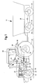
- FIG. 1 shows a combination of a tractor 10, in the form of an agricultural tractor, and a trailer 12.
- the towing vehicle 10 and the trailer 12 each have a hydraulically actuated brake system 14, 16, wherein the supply and control components for the brake systems 14, 16 predominantly are arranged on the towing vehicle 10.
- the brake systems 14, 16 have hydraulically actuated brake means 18, 20, which are designed as engageable with wheels 22 of the towing vehicle 10 and with wheels 24 of the trailer 12 engageable brake shoes.
- the actuation of the brake means 18, 20 takes place by hydraulic pressurization of corresponding brake lines 26, 28.
- the supply and control components for the brake systems 14, 16 include a hydraulic tank 30, a hydraulic pump 32, a hydraulic control 34 for the brake system 14 of the towing vehicle 10, a hydraulic control 36 for the trailer 12 and an electronic control 38 for electronically controllable components of the hydraulic controls 36 for the towing vehicle 10 or the trailer 12.
- a braking pressure triggering brake pedal 42 which is connected to the hydraulic control 34 of the brake system 14, and an electronic adjuster 44, with the control signals to the electronic controller 38 can be generated are arranged.
- the brake system 16 of the trailer 12 is hydraulically connected to the brake system 14 of the towing vehicle 10.
- FIG. 2 shows a first embodiment of the hydraulic control 36 for the trailer 12.
- the hydraulic control 36 has connecting lines 48, 50 which connect the hydraulic control 36 with the hydraulic tank 30 and the hydraulic pump 32. Furthermore, a hydraulic Line 52 is provided, which represents a connection to the hydraulic control 34 for the towing vehicle 10, and to the brake system 14 of the towing vehicle 10.
- a brake line 54 connects the hydraulic control 36 with the hydraulic coupling point 46 of the towing vehicle 10.
- the hydraulic control 36 further comprises a trailer brake valve 56 which is arranged between the connecting lines 48, 50 and the brake line 54.
- the trailer brake valve 56 is preferably designed as a hydraulically controllable proportional slide valve, which is hydraulically actuated via a first control pressure line 58 connected to the brake line 54 and via a second control pressure line 60 connected to the hydraulic line 52.
- the position of the trailer brake valve 56, and thus also the pressure in the brake line 54, consequently depends on the pressure difference between the first and second control pressure lines 58, 60 present at the trailer brake valve 56.
- the trailer brake valve 56 connects the hydraulic tank 30 in a first extreme position 62 and in a second extreme position 62 Extreme position 64, the hydraulic pump 32 with the brake line 54.
- the trailer brake valve 56 is formed as a proportionally controllable slide valve, any intermediate positions are proportional to the force acting on the Anticiangebremsventil 56 control pressures possible.
- the second control pressure line 60 is provided with a pressure reducing means in the form of a pressure reducing valve 66, wherein the hydraulic line 52 serves as a control pressure source for the second control pressure line 60.
- another component of the brake system 14 of the tractor 10 may serve as a control pressure source, as long as it is directly or indirectly connected to the applied brake pressure of the brake system 14.
- the pressure reducing valve 66 serves for Reduction or limitation of the control pressure with which the second control pressure line 60 is acted upon.
- the pressure reducing valve 66 is adjustable via an adjusting device designed as a manually adjustable biasing spring 68 and is thereby mechanically forced into a presettable open basic position.
- a counter to the biasing force of the biasing spring 68 acting control pressure is applied via a connected to the second control pressure line 60 third control pressure line 70 and moves the pressure reducing valve 66 in accordance with the height of the control pressure against the biasing force toward the closed position.
- the pressure reducing valve 66 is then closed via the third control pressure line 70 against the set biasing force.
- the setting of the maximum brake pressure for the trailer 12 is as mentioned by adjustment of the biasing spring 68 of the pressure reducing valve.
- the pilot pressure which shifts the trailer brake valve 56, can be set to a specific maximum pressure which, for example, does not fall below 100 bar or 120 bar (in France) and does not exceed 150 bar.
- FIG. 3 shows a further embodiment in which in addition to the in FIG. 2 illustrated embodiment, a bypass line 72 is arranged, with which the pressure reducing valve is bypassed and extending between the hydraulic line 52 and the second control pressure line 60.
- the bypass line 72 has a check valve 74 which closes in the direction of the second control pressure line 60.
- the check valve 74 facilitates a backflow of the hydraulic fluid with decreasing brake pressure, or control pressure in the second control pressure line 60.
- only a return flow of the hydraulic fluid is made possible.
- FIG. 4 Another embodiment is in FIG. 4 shown.
- An electronic adjusting device which interacts with the pretensioning spring 68, permits the electronic adjustment of the pressure reducing valve 66 or the pretensioning spring 68.
- the pretensioning spring can be proportionally amplified or relieved electronically.
- the adjusting device is preferably designed as an electronically controllable magnetic coil 76, which is adjustable via the electronic control 38. The adjustment of the magnetic coil 76 or the adjusting device takes place via the adjusting device 44 arranged in the vehicle cabin 40, via which corresponding control signals are given to the electronic control 38.
- the adjusting device can also be designed as an electric motor or as another electronic adjusting device, with which the biasing force acting on the pressure reducing valve is adjustable.
- the biasing spring 68 must be set or designed so that the regulations are still met in case of failure of the electronics.
- the max. Trailer brake pressure for example, 100 bar (120 bar in France) not lower and not exceed 150 bar.
- the biasing spring 68 can electronically increase by up to 50 bar in accordance with the electronic signal given by the adjusting means 44 be increased proportionally to set a maximum pressure for the trailer brake valve 56 of 150 bar, with increasing electronic signal acting on the pressure reducing valve 56 biasing force of the biasing spring 68 and solenoid 76 increases.
- the biasing spring 68 can be electronically relieved by up to 50 bar proportional to the predetermined by the setting means 44 electronic signal to set a maximum pressure for the trailer brake valve 56 of 150 bar, with increasing electronic Signal acting on the pressure reducing valve 56 biasing force of bias spring 68 and solenoid 76 decreases (not here in the logic in FIG. 4 shown).
- the maximum pressure being either 100 bar (120 bar in France) or 150 bar.
- a pressure sensor 77 disposed in the brake pipe 54 of the trailer 12, which is generally not essential to the operation of the hydraulic assembly, but more accurate adjustment of trailer brake pressure may be achieved via the electronic control unit 38 ,
- the advantage would be equivalent to a closed loop, in which the output pressure of the hydraulic arrangement or the trailer brake pressure continuously monitored and thereby an intended control is improved.
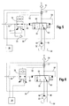
- FIGS. 5 and 6 each show a further embodiment, wherein instead of the pressure reducing valve 66 from the FIGS. 2 to 4 a switching valve 78 is arranged.
- the switching valve 78 has a closed position and a passage position, the passage position also here is preset by the biasing spring 68.
- the biasing force can also be electronically adjusted by an electronic adjusting device in the form of a magnetic coil 76 here.
- This embodiment can be done with and without bypass line 72, wherein the switching valve 78 at the in FIG. 6 illustrated embodiment (without bypass line 72) in the closed position, a return of the hydraulic control hydraulic fluid in the direction of the brake system 14 of the tractor 10 permits, which in the in FIG.
- FIGS. 5 illustrated embodiment by a separate, arranged in the bypass line 72, check valve 74 is ensured.
- the switching valve 78 in the FIGS. 5 and 6 is different than in the embodiments of the FIGS. 2 to 4 connected via a third control pressure line 70 'to the brake line 54 for the trailer 12.
- the switching valve 78 is automatically pressure-controlled brought into the closed position.
- the maximum pressure is, as in the previous embodiments, given by the presettable biasing force. It is thus not, as in the embodiments previously ( FIGS.
- a pressure sensor 77 is provided be disposed in the brake pipe 54 of the trailer 12.
- FIGS. 7 to 10 Further embodiments are in the FIGS. 7 to 10 illustrated therein, which is essentially therein of the embodiments with respect to the FIGS. 2 to 6 distinguish that the trailer brake valve 56 is additionally controlled via a further control pressure line 80 in parallel to the second control pressure line 70 in order to flexibly adjust a characteristic curve K of the trailer brake valve 56, ie to increase or attenuate the response of the trailer brake valve 56 (see FIG. 11 ).
- An enhanced response of a trailer brake valve 56 means in the present case that, in comparison to the previous embodiments with the same brake pressure in the brake system 14 of the towing vehicle 10, a higher brake pressure in the brake line 54 for the trailer 12 is achieved. Figuratively speaking, this means an increase in the slope of the characteristic K of the trailer brake valve 56 (see FIG.
- the trailer brake valve 56 is thus actuated by a first control pressure acting on a first side of the trailer brake valve 56 by the first control pressure line 58, and by second and third (parallel) control pressures respectively on the opposite second side of the trailer brake valve 56 by the second and third further control pressure line 60, 80 is applied, controlled.
- an electronically controllable, electro-proportional pressure reducing valve 82 is arranged, which connects the further control pressure line 80 both with the hydraulic tank 30 via a line 48 'and with the hydraulic pump 32 via a line 50'.
- the Further control pressure line 80 in conjunction with the electro-proportional pressure reducing valve 82 thus the total applied control pressure on the second side of the trailer brake valve 56 can be increased to increase the response of the trailer brake valve 56 and the slope of the characteristic K of the trailer brake valve 56 variable (flexible) so as to map a different characteristic K comprehensive map F for the trailer brake valve 56 (see FIG. 11 ).
- the electro-proportional pressure reducing valve 82 has a biasing spring 84 and an electronic adjusting device 86, for example, an electromagnetic coil, which counteracts the biasing spring 84.
- the biasing spring 84 holds the pressure reducing valve 82 in a home position in which no control pressure is built up by the hydraulic pump 32 in the further control pressure line 80.
- the electro-proportional pressure reducing valve 82 can be adjusted in proportion to the control signals, so that an additional control pressure for the trailer brake valve 56 can be established.
- FIGS. 7 and 8th As well as 9 and 10 illustrated hydraulic circuit diagrams show two different versions, as a trailer brake valve 56 can be operated flexibly according to the above, the in the FIGS. 7 and 8th Embodiments shown have arranged in the second control pressure line 60 adjustable pressure reducing valve 66 which is connected via a third control pressure line 70 to the second control pressure line 60 and in the Figures 9 and 10 illustrated embodiments a in the second control pressure line 60th arranged adjustable switching valve 78, which is connected via a third control pressure line 70 'to the brake line 54 for the trailer 12.
- adjustable pressure reducing valve 66 and by the adjustable switching valve 78 the control pressure in the second control pressure line 60 according to the explanations to the FIGS. 2 to 6 be limited.
- FIGS. 7 and 8th differ in that the pressure reducing valve 66, analogous to those in the FIGS. 2 and 3 illustrated embodiments, once without and once with bypass line 72 with check valve 74 is executed ( FIG. 7 respectively. FIG. 8 ).
- the Figures 9 and 10 differ in that the switching valve 78, analogous to those in the FIGS. 5 and 6 illustrated embodiments, once without and once with bypass line 72 with check valve 74 is executed ( FIG. 9 respectively. FIG. 10 ).
- a return possibility of the hydraulic control pressure fluid in the closed position of the switching valve 72 (FIG. FIG. 9 ) or via a separately arranged in the bypass line 72 check valve 74 ( FIG. 10 ) ensures a pressure reduction in the control pressure line.
- electro-proportional pressure reducing valve 82 is in the embodiments of the FIGS. 7 to 10 a pressure sensor 88, which is connected to the hydraulic line 52 serving as a control pressure source, by means of which a pressure in the brake system 14 of the towing vehicle 10 can be detected. Both the pressure sensor 88 and the electro-proportional pressure reducing valve 82 and the adjusting device 86 are connected to the electronic control 38. Corresponding control signals for the Electro-proportional pressure reducing valve 82 can be predetermined or generated by the adjusting device 44 in conjunction with the electronic control 38. It can also in the embodiments according to the FIGS. 7 to 10 as already mentioned in the FIG. 4 described embodiment, a pressure sensor 77 may be provided, which is arranged in the brake line 54 of the trailer 12.
- FIGS. 7 to 10 shown essential feature is that initially limiting the maximum brake pressure for the trailer 12 by limiting the control pressure in the second control pressure line 60 via the adjustable pressure reducing valve 66 and via the adjustable switching valve 78 analogous to those in the FIGS. 2 to 6 illustrated embodiments takes place.
- a deceleration of the trailer 12 can occur in the event of failure of the electrical system. It is important that this maximum brake pressure is fixed and should not be adjustable (except for the difference 100 bar and 120 bar, which may be useful for reasons of variety of parts, so that one and the same pressure reducing valve 66, for example, the specifications for 100 bar and for The brake characteristic or the characteristic curve K of the trailer brake valve 56 is designed or set in a basic setting so that in the basic position of the electro-proportional pressure reducing valve 82, the vehicle combination (10, 12) in its most unfavorable Condition can be braked with respect to the French regulation without violating the regulation (eg lower characteristic K in FIG. 11 ). It is of course also another (greater or lesser) slope of the characteristic curve K of the trailer brake valve 56 conceivable, but the vehicle should not be braked too aggressively, since this mode is required only in case of failure
- the characteristic curve K which represents a smaller slope and a minimum maximum pressure (lower characteristic curve in FIG. 11 ) reflects the braking behavior of the trailer brake valve 56 in case of failure of the electronics again.
- This basic setting of the control pressure for the trailer brake valve 56 is now superimposed by a further control pressure, which is generated by the electro-proportional pressure reducing valve 82 and the associated hydraulic supply line to the hydraulic pump 32.
- the electronic control 38 evaluates the pressure measured in the brake system 14 of the towing vehicle 10 with the illustrated pressure sensor 88 and calculates the pressure signal to be generated by the electroproportional pressure reducing valve 82 based on the characteristic curve K predefined by the operator via the setting device 44, whereupon the pressure is controlled by the electronic control 38 generated control of the adjustment 86 takes place.
- failure of the electronics is automatically set the basic position of the electro-proportional pressure reducing valve 82 and the basic setting of the characteristic.
Landscapes
- Engineering & Computer Science (AREA)
- Transportation (AREA)
- Mechanical Engineering (AREA)
- Regulating Braking Force (AREA)
- Braking Systems And Boosters (AREA)
- Lubricants (AREA)
Claims (14)
- Agencement hydraulique pour freiner une remorque (12), comprenant une conduite de frein (54) pouvant être connectée hydrauliquement à une installation de frein (16) d'une remorque (12), une source hydraulique (32), un réservoir hydraulique (30), une soupape de frein de remorque (56) à commande hydraulique reliant la source hydraulique (32) et le réservoir hydraulique (30) à la conduite de frein (54), une première conduite de pression de commande (58) s'étendant entre la conduite de frein (54) et la soupape de frein de remorque (56), une deuxième conduite de pression de commande (60) s'étendant la soupape de frein de remorque (56) et une source de pression de commande, et un moyen réducteur de pression ajustable, disposé dans la deuxième conduite de pression de commande (60) pour la commande de la pression de commande dans la deuxième conduite de pression de commande (60), caractérisé en ce que la source de pression de commande est réalisée sous forme d'une partie d'une commande hydraulique (34) d'une installation de frein (14) d'un véhicule tracteur (10) tirant la remorque (12), et le moyen réducteur de pression peut être forcé mécaniquement dans une position de base ouverte par une force de précontrainte ajustable.
- Agencement hydraulique selon la revendication 1, caractérisé en ce que la source de pression de commande est réalisée sous forme d'une conduite hydraulique (52) connectée à l'installation de frein (14) du véhicule tracteur (10).
- Agencement hydraulique selon la revendication 1 ou 2, caractérisé en ce qu'une soupape de non retour (74) montée en parallèle avec le moyen réducteur de pression est disposée dans une conduite de dérivation (72) et se ferme dans la direction de la soupape de frein de remorque (56).
- Agencement hydraulique selon l'une quelconque des revendications 1 à 3, caractérisé en ce que le moyen réducteur de pression est réalisé dans la deuxième conduite de pression de commande (60) sous forme de soupape réductrice de pression (66) à commande hydraulique, qui ferme la deuxième conduite de pression de commande (60) à partir d'une pression de commande déterminée dans la deuxième conduite de pression de commande (60).
- Agencement hydraulique selon l'une quelconque des revendications 1 à 3, caractérisé en ce que le moyen réducteur de pression est réalisé sous forme de soupape de commutation (78) qui ferme la deuxième conduite de pression de commande (60) dans la direction de la soupape de frein de remorque (56) à partir d'une pression déterminée dans la conduite de frein (54).
- Agencement hydraulique selon l'une quelconque des revendications 1 à 5, caractérisé en ce que le moyen réducteur de pression présente un ressort de précontrainte réglable (68), avec lequel on peut produire une force de précontrainte qui force le moyen réducteur de pression dans la position de base ouverte.
- Agencement hydraulique selon la revendication 6, caractérisé en ce que le moyen réducteur de pression présente des moyens de réglage électroniques (76), qui permettent de produire une force de réglage qui agit à l'encontre de la force de précontrainte du ressort de précontrainte (68) ou qui l'augmente.
- Agencement hydraulique selon l'une quelconque des revendications 1 à 7, caractérisé en ce que la soupape de frein de remorque (56) est réalisée sous forme de soupape à tiroir proportionnelle.
- Agencement hydraulique selon l'une quelconque des revendications 1 à 8, caractérisé en ce que l'on prévoit une autre conduite de pression de commande (80) avec laquelle la soupape de frein de remorque (56) peut être commandée hydrauliquement en plus de la première et de la deuxième conduite de pression de commande (58, 60), une soupape de réduction de pression (82) à commande électronique étant prévue, laquelle relie la source hydraulique (32) et le réservoir hydraulique (30) à l'autre conduite de pression de commande (80).
- Agencement hydraulique selon l'une quelconque des revendications 1 à 9, caractérisé en ce qu'un capteur de pression (88) est prévu, lequel permet de détecter la pression de l'installation de frein (14) du véhicule tracteur (10).
- Agencement hydraulique selon l'une quelconque des revendications 1 à 10, caractérisé en ce qu'un capteur de pression (77) est prévu, lequel permet de détecter la pression de la conduite de frein (54) de la remorque (12).
- Agencement hydraulique selon l'une quelconque des revendications 1 à 11, caractérisé en ce qu'une unité de commande électronique (38) est prévue pour commander les soupapes à commande ou commutation électronique (66, 78, 82).
- Agencement hydraulique selon la revendication 12, caractérisé en ce que l'unité de commande électronique (38) est appropriée pour analyser une valeur de pression fournie par le capteur de pression (77, 88) dans une opération de commande.
- Combinaison d'une remorque (12) et d'un véhicule tracteur (10), avec une installation de frein hydraulique (14) pour la remorque (12) et une installation de frein hydraulique (16) pour le véhicule tracteur (10), caractérisée en ce que l'on prévoit un agencement hydraulique selon l'une quelconque des revendications 1 à 13.
Applications Claiming Priority (1)
| Application Number | Priority Date | Filing Date | Title |
|---|---|---|---|
| DE102006007575A DE102006007575A1 (de) | 2006-02-18 | 2006-02-18 | Hydraulische Anordnung |
Publications (3)
| Publication Number | Publication Date |
|---|---|
| EP1820708A2 EP1820708A2 (fr) | 2007-08-22 |
| EP1820708A3 EP1820708A3 (fr) | 2008-06-18 |
| EP1820708B1 true EP1820708B1 (fr) | 2009-08-12 |
Family
ID=38027672
Family Applications (1)
| Application Number | Title | Priority Date | Filing Date |
|---|---|---|---|
| EP07102574A Active EP1820708B1 (fr) | 2006-02-18 | 2007-02-16 | Agencement hydraulique |
Country Status (4)
| Country | Link |
|---|---|
| US (1) | US8646852B2 (fr) |
| EP (1) | EP1820708B1 (fr) |
| AT (1) | ATE439281T1 (fr) |
| DE (2) | DE102006007575A1 (fr) |
Cited By (7)
| Publication number | Priority date | Publication date | Assignee | Title |
|---|---|---|---|---|
| US10670479B2 (en) | 2018-02-27 | 2020-06-02 | Methode Electronics, Inc. | Towing systems and methods using magnetic field sensing |
| US10696109B2 (en) | 2017-03-22 | 2020-06-30 | Methode Electronics Malta Ltd. | Magnetolastic based sensor assembly |
| US11084342B2 (en) | 2018-02-27 | 2021-08-10 | Methode Electronics, Inc. | Towing systems and methods using magnetic field sensing |
| US11135882B2 (en) | 2018-02-27 | 2021-10-05 | Methode Electronics, Inc. | Towing systems and methods using magnetic field sensing |
| US11221262B2 (en) | 2018-02-27 | 2022-01-11 | Methode Electronics, Inc. | Towing systems and methods using magnetic field sensing |
| US11491832B2 (en) | 2018-02-27 | 2022-11-08 | Methode Electronics, Inc. | Towing systems and methods using magnetic field sensing |
| EP3533673B1 (fr) * | 2018-03-03 | 2024-12-11 | ZF CV Systems Europe BV | Procédé de commande de frein d'un véhicule tracté |
Families Citing this family (8)
| Publication number | Priority date | Publication date | Assignee | Title |
|---|---|---|---|---|
| DE102009050793A1 (de) * | 2009-10-27 | 2011-04-28 | Robert Bosch Gmbh | Adaptives Bremssystem für Lastanhänger |
| ITTO20110587A1 (it) * | 2011-07-04 | 2013-01-05 | Cnh Italia Spa | Metodo e apparato per la frenatura di un trattore munito di un rimorchio |
| CN103661337A (zh) * | 2012-09-05 | 2014-03-26 | 卡特彼勒公司 | 释放抛锚机器驻车制动器的方法和系统及含该系统的机器 |
| EP3448143A4 (fr) * | 2016-04-26 | 2020-04-01 | Vermeer Manufacturing Company | Système de commande de frein dans un système hydraulique auxiliaire |
| US11014417B2 (en) | 2018-02-27 | 2021-05-25 | Methode Electronics, Inc. | Towing systems and methods using magnetic field sensing |
| CN108953419B (zh) * | 2018-09-25 | 2023-12-01 | 杭叉集团股份有限公司 | 一种液压刹车系统 |
| DE102019102136A1 (de) * | 2019-01-29 | 2020-07-30 | Horsch Leeb Application Systems Gmbh | Bremssystem für einen landwirtschaftlich einsetzbaren Anhänger sowie landwirtschaftlicher Zugverbund, umfassend eine Zugmaschine und wenigstens einen damit gekoppelten Anhänger |
| DE102021133758A1 (de) * | 2021-12-17 | 2023-06-22 | Zf Cv Systems Global Gmbh | Verfahren zur Traktionssteuerung eines Fahrzeugs oder eines Fahrzeuggespanns |
Family Cites Families (12)
| Publication number | Priority date | Publication date | Assignee | Title |
|---|---|---|---|---|
| GB911096A (en) | 1959-09-23 | 1962-11-21 | Automotive Prod Co Ltd | Improvements in or relating to liquid pressure braking systems for vehicles |
| GB1249312A (en) * | 1968-02-01 | 1971-10-13 | Girling Ltd | Improvements in hydraulic systems, such as vehicle braking systems |
| GB1332126A (en) * | 1969-12-18 | 1973-10-03 | Massey Ferguson Services Nv | Apparatus for controlling auxiliary hydraulic services in tractors or towing vehicles |
| DE2812765A1 (de) | 1978-03-23 | 1979-09-27 | Bosch Gmbh Robert | Bremseinrichtung fuer den anhaenger eines fahrzeugs, das einen von einer druckmittelquelle gespeisten hydraulikkreis mit einem verbraucher hat |
| DE2825847A1 (de) * | 1978-06-13 | 1979-12-20 | Fritzmeier Ag | Hydraulische anhaengerbremsanlage fuer nutzfahrzeuge |
| US4343517A (en) * | 1979-02-23 | 1982-08-10 | Clayton Dewandre & Company Limited | Hydraulic braking systems for tractor-trailer combinations |
| US4243271A (en) * | 1979-05-31 | 1981-01-06 | Massey-Ferguson Inc. | Hydraulic braking system |
| IT1129456B (it) | 1980-12-18 | 1986-06-04 | Fiat Trattori Spa | Sistema idraulico di frenatura per rimorichi di autoveicoli particoalrmente per rimorchi agricoli |
| DE3133964A1 (de) | 1981-08-27 | 1983-03-10 | Robert Bosch Gmbh, 7000 Stuttgart | Hydraulische steuereinrichtung |
| DE19514733B4 (de) * | 1995-04-21 | 2004-08-12 | Bosch Rexroth Ag | Bremsventil |
| US6729696B2 (en) * | 2001-05-08 | 2004-05-04 | Bendix Commercial Vehicle Systems, Llc | Two step park release valve |
| DE10355955A1 (de) | 2003-12-01 | 2005-06-30 | Bosch Rexroth Ag | Hydraulische Anhängerbremseinrichtung |
-
2006
- 2006-02-18 DE DE102006007575A patent/DE102006007575A1/de not_active Withdrawn
-
2007
- 2007-02-14 US US11/674,715 patent/US8646852B2/en active Active
- 2007-02-16 DE DE502007001263T patent/DE502007001263D1/de active Active
- 2007-02-16 EP EP07102574A patent/EP1820708B1/fr active Active
- 2007-02-16 AT AT07102574T patent/ATE439281T1/de active
Cited By (8)
| Publication number | Priority date | Publication date | Assignee | Title |
|---|---|---|---|---|
| US10696109B2 (en) | 2017-03-22 | 2020-06-30 | Methode Electronics Malta Ltd. | Magnetolastic based sensor assembly |
| US10940726B2 (en) | 2017-03-22 | 2021-03-09 | Methode Electronics Malta Ltd. | Magnetoelastic based sensor assembly |
| US10670479B2 (en) | 2018-02-27 | 2020-06-02 | Methode Electronics, Inc. | Towing systems and methods using magnetic field sensing |
| US11084342B2 (en) | 2018-02-27 | 2021-08-10 | Methode Electronics, Inc. | Towing systems and methods using magnetic field sensing |
| US11135882B2 (en) | 2018-02-27 | 2021-10-05 | Methode Electronics, Inc. | Towing systems and methods using magnetic field sensing |
| US11221262B2 (en) | 2018-02-27 | 2022-01-11 | Methode Electronics, Inc. | Towing systems and methods using magnetic field sensing |
| US11491832B2 (en) | 2018-02-27 | 2022-11-08 | Methode Electronics, Inc. | Towing systems and methods using magnetic field sensing |
| EP3533673B1 (fr) * | 2018-03-03 | 2024-12-11 | ZF CV Systems Europe BV | Procédé de commande de frein d'un véhicule tracté |
Also Published As
| Publication number | Publication date |
|---|---|
| EP1820708A3 (fr) | 2008-06-18 |
| US20070205656A1 (en) | 2007-09-06 |
| US8646852B2 (en) | 2014-02-11 |
| DE502007001263D1 (de) | 2009-09-24 |
| ATE439281T1 (de) | 2009-08-15 |
| EP1820708A2 (fr) | 2007-08-22 |
| DE102006007575A1 (de) | 2007-08-23 |
Similar Documents
| Publication | Publication Date | Title |
|---|---|---|
| EP1820708B1 (fr) | Agencement hydraulique | |
| DE102009045191C5 (de) | Verfahren zum Betrieb einer Bremseinrichtung für ein hydraulisch gebremstes Zugfahrzeug | |
| EP2913236A2 (fr) | Module de freinage pour un véhicule de traction à freinage hydraulique pouvant être couplé à une remorque à freinage pneumatique | |
| DE10354056A1 (de) | Ventileinrichtung für eine Luftfederungseinrichtung für ein Fahrzeug | |
| DE4108915C2 (de) | Hydraulische Einrichtung zur Druckmittelversorgung eines bevorrechtigten Primärlastkreises | |
| DE102006010695B4 (de) | Hydraulische Lenkung | |
| DE4235707B4 (de) | Hydrostatisches Antriebssystem | |
| DE102005002699B4 (de) | Bremsventilanordung | |
| EP1538044B1 (fr) | Dispositif hydraulique de frein de remorque | |
| EP2268516B1 (fr) | Générateur de pression d un dispositif de freinage hydraulique de véhicule et procédé de fonctionnement associé | |
| EP3398418A1 (fr) | Système hydraulique d'une machine à usage agricole ou de travaux publics | |
| DE102009031742A1 (de) | Fahrbare Arbeitsmaschine mit einer als Betriebsbremse und als automatische Feststellbremse betreibbaren Bremse | |
| DE102009047035A1 (de) | Steuerungssystem mit aufgelösten Steuerkanten | |
| EP2712787A2 (fr) | Véhicule agricole doté d'une direction assistée | |
| DE102004027971B4 (de) | Hydraulische Lenkeinrichtung | |
| EP0797727A1 (fr) | Systeme hydraulique pour vehicule a moteur | |
| EP2157320A1 (fr) | Commande hydraulique pour un moteur hydraulique | |
| DE3842348A1 (de) | Antriebsschlupfregel- und fahrgeschwindigkeitsbegrenzungs-einrichtung | |
| DE10151831B4 (de) | Hydraulikanlage für ein Flurförderzeug | |
| DE102009012770A1 (de) | Hydrauliksystem einer Fahrzeug-Hinterachsenlenkung | |
| DE102006046854B4 (de) | Hydrostatische Verstelleinheit mit einem Servosystem und einer das Servosystem steuernden Ventileinheit | |
| EP3461707A1 (fr) | Système de commande d'un dispositif de freinage à commande hydraulique | |
| DE102010055716A1 (de) | Hydraulischer Antrieb | |
| DE102011016591A1 (de) | Elektrohydraulische Lenkung | |
| EP1759949B1 (fr) | Soupape de freinage pour un remorque |
Legal Events
| Date | Code | Title | Description |
|---|---|---|---|
| PUAI | Public reference made under article 153(3) epc to a published international application that has entered the european phase |
Free format text: ORIGINAL CODE: 0009012 |
|
| AK | Designated contracting states |
Kind code of ref document: A2 Designated state(s): AT BE BG CH CY CZ DE DK EE ES FI FR GB GR HU IE IS IT LI LT LU LV MC NL PL PT RO SE SI SK TR |
|
| AX | Request for extension of the european patent |
Extension state: AL BA HR MK YU |
|
| PUAL | Search report despatched |
Free format text: ORIGINAL CODE: 0009013 |
|
| AK | Designated contracting states |
Kind code of ref document: A3 Designated state(s): AT BE BG CH CY CZ DE DK EE ES FI FR GB GR HU IE IS IT LI LT LU LV MC NL PL PT RO SE SI SK TR |
|
| AX | Request for extension of the european patent |
Extension state: AL BA HR MK RS |
|
| RIC1 | Information provided on ipc code assigned before grant |
Ipc: B60T 11/10 20060101ALI20080514BHEP Ipc: B60T 11/34 20060101ALI20080514BHEP Ipc: B60T 7/20 20060101AFI20070523BHEP |
|
| 17P | Request for examination filed |
Effective date: 20081218 |
|
| GRAP | Despatch of communication of intention to grant a patent |
Free format text: ORIGINAL CODE: EPIDOSNIGR1 |
|
| AKX | Designation fees paid |
Designated state(s): AT BE BG CH CY CZ DE DK EE ES FI FR GB GR HU IE IS IT LI LT LU LV MC NL PL PT RO SE SI SK TR |
|
| GRAS | Grant fee paid |
Free format text: ORIGINAL CODE: EPIDOSNIGR3 |
|
| GRAA | (expected) grant |
Free format text: ORIGINAL CODE: 0009210 |
|
| AK | Designated contracting states |
Kind code of ref document: B1 Designated state(s): AT BE BG CH CY CZ DE DK EE ES FI FR GB GR HU IE IS IT LI LT LU LV MC NL PL PT RO SE SI SK TR |
|
| REG | Reference to a national code |
Ref country code: GB Ref legal event code: FG4D Free format text: NOT ENGLISH |
|
| REG | Reference to a national code |
Ref country code: CH Ref legal event code: EP Ref country code: CH Ref legal event code: NV Representative=s name: E. BLUM & CO. AG PATENT- UND MARKENANWAELTE VSP |
|
| REG | Reference to a national code |
Ref country code: IE Ref legal event code: FG4D |
|
| REF | Corresponds to: |
Ref document number: 502007001263 Country of ref document: DE Date of ref document: 20090924 Kind code of ref document: P |
|
| LTIE | Lt: invalidation of european patent or patent extension |
Effective date: 20090812 |
|
| PG25 | Lapsed in a contracting state [announced via postgrant information from national office to epo] |
Ref country code: SE Free format text: LAPSE BECAUSE OF FAILURE TO SUBMIT A TRANSLATION OF THE DESCRIPTION OR TO PAY THE FEE WITHIN THE PRESCRIBED TIME-LIMIT Effective date: 20090812 Ref country code: LT Free format text: LAPSE BECAUSE OF FAILURE TO SUBMIT A TRANSLATION OF THE DESCRIPTION OR TO PAY THE FEE WITHIN THE PRESCRIBED TIME-LIMIT Effective date: 20090812 Ref country code: ES Free format text: LAPSE BECAUSE OF FAILURE TO SUBMIT A TRANSLATION OF THE DESCRIPTION OR TO PAY THE FEE WITHIN THE PRESCRIBED TIME-LIMIT Effective date: 20091123 Ref country code: IS Free format text: LAPSE BECAUSE OF FAILURE TO SUBMIT A TRANSLATION OF THE DESCRIPTION OR TO PAY THE FEE WITHIN THE PRESCRIBED TIME-LIMIT Effective date: 20091212 Ref country code: FI Free format text: LAPSE BECAUSE OF FAILURE TO SUBMIT A TRANSLATION OF THE DESCRIPTION OR TO PAY THE FEE WITHIN THE PRESCRIBED TIME-LIMIT Effective date: 20090812 |
|
| PG25 | Lapsed in a contracting state [announced via postgrant information from national office to epo] |
Ref country code: LV Free format text: LAPSE BECAUSE OF FAILURE TO SUBMIT A TRANSLATION OF THE DESCRIPTION OR TO PAY THE FEE WITHIN THE PRESCRIBED TIME-LIMIT Effective date: 20090812 Ref country code: SI Free format text: LAPSE BECAUSE OF FAILURE TO SUBMIT A TRANSLATION OF THE DESCRIPTION OR TO PAY THE FEE WITHIN THE PRESCRIBED TIME-LIMIT Effective date: 20090812 Ref country code: PL Free format text: LAPSE BECAUSE OF FAILURE TO SUBMIT A TRANSLATION OF THE DESCRIPTION OR TO PAY THE FEE WITHIN THE PRESCRIBED TIME-LIMIT Effective date: 20090812 |
|
| REG | Reference to a national code |
Ref country code: IE Ref legal event code: FD4D |
|
| PG25 | Lapsed in a contracting state [announced via postgrant information from national office to epo] |
Ref country code: PT Free format text: LAPSE BECAUSE OF FAILURE TO SUBMIT A TRANSLATION OF THE DESCRIPTION OR TO PAY THE FEE WITHIN THE PRESCRIBED TIME-LIMIT Effective date: 20091212 Ref country code: BG Free format text: LAPSE BECAUSE OF FAILURE TO SUBMIT A TRANSLATION OF THE DESCRIPTION OR TO PAY THE FEE WITHIN THE PRESCRIBED TIME-LIMIT Effective date: 20091112 |
|
| PG25 | Lapsed in a contracting state [announced via postgrant information from national office to epo] |
Ref country code: EE Free format text: LAPSE BECAUSE OF FAILURE TO SUBMIT A TRANSLATION OF THE DESCRIPTION OR TO PAY THE FEE WITHIN THE PRESCRIBED TIME-LIMIT Effective date: 20090812 Ref country code: CZ Free format text: LAPSE BECAUSE OF FAILURE TO SUBMIT A TRANSLATION OF THE DESCRIPTION OR TO PAY THE FEE WITHIN THE PRESCRIBED TIME-LIMIT Effective date: 20090812 Ref country code: IE Free format text: LAPSE BECAUSE OF FAILURE TO SUBMIT A TRANSLATION OF THE DESCRIPTION OR TO PAY THE FEE WITHIN THE PRESCRIBED TIME-LIMIT Effective date: 20090812 Ref country code: DK Free format text: LAPSE BECAUSE OF FAILURE TO SUBMIT A TRANSLATION OF THE DESCRIPTION OR TO PAY THE FEE WITHIN THE PRESCRIBED TIME-LIMIT Effective date: 20090812 Ref country code: RO Free format text: LAPSE BECAUSE OF FAILURE TO SUBMIT A TRANSLATION OF THE DESCRIPTION OR TO PAY THE FEE WITHIN THE PRESCRIBED TIME-LIMIT Effective date: 20090812 |
|
| PG25 | Lapsed in a contracting state [announced via postgrant information from national office to epo] |
Ref country code: SK Free format text: LAPSE BECAUSE OF FAILURE TO SUBMIT A TRANSLATION OF THE DESCRIPTION OR TO PAY THE FEE WITHIN THE PRESCRIBED TIME-LIMIT Effective date: 20090812 |
|
| PLBE | No opposition filed within time limit |
Free format text: ORIGINAL CODE: 0009261 |
|
| STAA | Information on the status of an ep patent application or granted ep patent |
Free format text: STATUS: NO OPPOSITION FILED WITHIN TIME LIMIT |
|
| 26N | No opposition filed |
Effective date: 20100517 |
|
| PG25 | Lapsed in a contracting state [announced via postgrant information from national office to epo] |
Ref country code: GR Free format text: LAPSE BECAUSE OF FAILURE TO SUBMIT A TRANSLATION OF THE DESCRIPTION OR TO PAY THE FEE WITHIN THE PRESCRIBED TIME-LIMIT Effective date: 20091113 Ref country code: MC Free format text: LAPSE BECAUSE OF NON-PAYMENT OF DUE FEES Effective date: 20100301 |
|
| PGRI | Patent reinstated in contracting state [announced from national office to epo] |
Ref country code: IT Effective date: 20110501 |
|
| PG25 | Lapsed in a contracting state [announced via postgrant information from national office to epo] |
Ref country code: CY Free format text: LAPSE BECAUSE OF FAILURE TO SUBMIT A TRANSLATION OF THE DESCRIPTION OR TO PAY THE FEE WITHIN THE PRESCRIBED TIME-LIMIT Effective date: 20090812 |
|
| PG25 | Lapsed in a contracting state [announced via postgrant information from national office to epo] |
Ref country code: LU Free format text: LAPSE BECAUSE OF NON-PAYMENT OF DUE FEES Effective date: 20100216 Ref country code: HU Free format text: LAPSE BECAUSE OF FAILURE TO SUBMIT A TRANSLATION OF THE DESCRIPTION OR TO PAY THE FEE WITHIN THE PRESCRIBED TIME-LIMIT Effective date: 20100213 |
|
| PG25 | Lapsed in a contracting state [announced via postgrant information from national office to epo] |
Ref country code: TR Free format text: LAPSE BECAUSE OF FAILURE TO SUBMIT A TRANSLATION OF THE DESCRIPTION OR TO PAY THE FEE WITHIN THE PRESCRIBED TIME-LIMIT Effective date: 20090812 |
|
| REG | Reference to a national code |
Ref country code: FR Ref legal event code: PLFP Year of fee payment: 10 |
|
| REG | Reference to a national code |
Ref country code: FR Ref legal event code: PLFP Year of fee payment: 11 |
|
| REG | Reference to a national code |
Ref country code: FR Ref legal event code: PLFP Year of fee payment: 12 |
|
| PGFP | Annual fee paid to national office [announced via postgrant information from national office to epo] |
Ref country code: NL Payment date: 20240226 Year of fee payment: 18 |
|
| PGFP | Annual fee paid to national office [announced via postgrant information from national office to epo] |
Ref country code: AT Payment date: 20240201 Year of fee payment: 18 |
|
| PGFP | Annual fee paid to national office [announced via postgrant information from national office to epo] |
Ref country code: DE Payment date: 20240119 Year of fee payment: 18 Ref country code: CH Payment date: 20240301 Year of fee payment: 18 Ref country code: GB Payment date: 20240227 Year of fee payment: 18 |
|
| PGFP | Annual fee paid to national office [announced via postgrant information from national office to epo] |
Ref country code: IT Payment date: 20240222 Year of fee payment: 18 Ref country code: FR Payment date: 20240226 Year of fee payment: 18 Ref country code: BE Payment date: 20240227 Year of fee payment: 18 |
|
| REG | Reference to a national code |
Ref country code: DE Ref legal event code: R119 Ref document number: 502007001263 Country of ref document: DE |
|
| REG | Reference to a national code |
Ref country code: CH Ref legal event code: PL |
|
| REG | Reference to a national code |
Ref country code: NL Ref legal event code: MM Effective date: 20250301 |
|
| REG | Reference to a national code |
Ref country code: AT Ref legal event code: MM01 Ref document number: 439281 Country of ref document: AT Kind code of ref document: T Effective date: 20250216 |
|
| PG25 | Lapsed in a contracting state [announced via postgrant information from national office to epo] |
Ref country code: AT Free format text: LAPSE BECAUSE OF NON-PAYMENT OF DUE FEES Effective date: 20250216 |
|
| PG25 | Lapsed in a contracting state [announced via postgrant information from national office to epo] |
Ref country code: CH Free format text: LAPSE BECAUSE OF NON-PAYMENT OF DUE FEES Effective date: 20250228 |
|
| GBPC | Gb: european patent ceased through non-payment of renewal fee |
Effective date: 20250216 |
|
| PG25 | Lapsed in a contracting state [announced via postgrant information from national office to epo] |
Ref country code: NL Free format text: LAPSE BECAUSE OF NON-PAYMENT OF DUE FEES Effective date: 20250301 |
|
| REG | Reference to a national code |
Ref country code: BE Ref legal event code: MM Effective date: 20250228 |
|
| PG25 | Lapsed in a contracting state [announced via postgrant information from national office to epo] |
Ref country code: DE Free format text: LAPSE BECAUSE OF NON-PAYMENT OF DUE FEES Effective date: 20250902 |
|
| PG25 | Lapsed in a contracting state [announced via postgrant information from national office to epo] |
Ref country code: GB Free format text: LAPSE BECAUSE OF NON-PAYMENT OF DUE FEES Effective date: 20250216 |
|
| PG25 | Lapsed in a contracting state [announced via postgrant information from national office to epo] |
Ref country code: FR Free format text: LAPSE BECAUSE OF NON-PAYMENT OF DUE FEES Effective date: 20250228 |
|
| PG25 | Lapsed in a contracting state [announced via postgrant information from national office to epo] |
Ref country code: BE Free format text: LAPSE BECAUSE OF NON-PAYMENT OF DUE FEES Effective date: 20250228 |